EP0438794B1 - Tuyère de remplissage pour machines de remplissage pour remplir des sacs à valve - Google Patents
Tuyère de remplissage pour machines de remplissage pour remplir des sacs à valve Download PDFInfo
- Publication number
- EP0438794B1 EP0438794B1 EP90125633A EP90125633A EP0438794B1 EP 0438794 B1 EP0438794 B1 EP 0438794B1 EP 90125633 A EP90125633 A EP 90125633A EP 90125633 A EP90125633 A EP 90125633A EP 0438794 B1 EP0438794 B1 EP 0438794B1
- Authority
- EP
- European Patent Office
- Prior art keywords
- filling
- inner tube
- outer tube
- valve
- filling material
- Prior art date
- Legal status (The legal status is an assumption and is not a legal conclusion. Google has not performed a legal analysis and makes no representation as to the accuracy of the status listed.)
- Expired - Lifetime
Links
- 239000000463 material Substances 0.000 claims abstract description 14
- 230000005484 gravity Effects 0.000 claims abstract description 3
- 239000000945 filler Substances 0.000 description 15
- 238000011109 contamination Methods 0.000 description 2
- 238000005056 compaction Methods 0.000 description 1
- 230000006835 compression Effects 0.000 description 1
- 238000007906 compression Methods 0.000 description 1
- 238000010276 construction Methods 0.000 description 1
- 230000007812 deficiency Effects 0.000 description 1
- 238000005192 partition Methods 0.000 description 1
Images

Classifications
-
- B—PERFORMING OPERATIONS; TRANSPORTING
- B65—CONVEYING; PACKING; STORING; HANDLING THIN OR FILAMENTARY MATERIAL
- B65B—MACHINES, APPARATUS OR DEVICES FOR, OR METHODS OF, PACKAGING ARTICLES OR MATERIALS; UNPACKING
- B65B1/00—Packaging fluent solid material, e.g. powders, granular or loose fibrous material, loose masses of small articles, in individual containers or receptacles, e.g. bags, sacks, boxes, cartons, cans, or jars
- B65B1/04—Methods of, or means for, filling the material into the containers or receptacles
- B65B1/18—Methods of, or means for, filling the material into the containers or receptacles for filling valve-bags
-
- B—PERFORMING OPERATIONS; TRANSPORTING
- B65—CONVEYING; PACKING; STORING; HANDLING THIN OR FILAMENTARY MATERIAL
- B65B—MACHINES, APPARATUS OR DEVICES FOR, OR METHODS OF, PACKAGING ARTICLES OR MATERIALS; UNPACKING
- B65B39/00—Nozzles, funnels or guides for introducing articles or materials into containers or wrappers
- B65B39/04—Nozzles, funnels or guides for introducing articles or materials into containers or wrappers having air-escape, or air-withdrawal, passages
Definitions
- the invention relates to a filler neck for filling machines for filling valve sacks, with an outer tube, via which the valve sacks to be filled can be plugged with their valve opening, and an inner tube arranged in the outer tube for guiding the filling material and with a device for closing the inner tube.
- Such a filling support is known from DE-A-38 09 593. It serves to fill valve sacks with, in particular, powdery filling material and consists of an inner tube guiding the filling material flow and an outer tube surrounding it, forming an intermediate space, the intermediate space being able to be acted upon by vacuum, which is created by openings in the wall of the outer tube at which it is filled attached valve bag attacks and its bag valve at the filler neck.
- a suction channel which is connected to the interior of the valve sack, is also provided for extracting the air displaced during filling.
- the outer and inner tubes each end at their front ends in an end cone, in the lateral surfaces of which an outlet opening is arranged.
- the inner tube is designed to be rotatable about its axis, so that a rotation thereof relative to the outer tube enables the outlet openings to be congruent with one another or to be offset from one another for the purpose of closing the filler neck.
- This filler neck is a complex construction and also leaves something to be desired in so far as contamination of the bag valve, which means a leaky valve, cannot be avoided with certainty.
- the advantages that can be achieved in this way are, in particular, that the control of the proposed filler neck takes place automatically, that is to say without additional control means, and contamination of the bag valve is excluded.
- the closure flap is provided with an adjustable stop to limit the opening angle of the closure flap and, in its open position, serves as a guide surface for deflecting the Product flow. The direction of the product flow can thus be controlled, so that it can be ensured that the suction channel is kept free of product.
- the outlet cross-section of the filler neck can be influenced by adjusting the maximum opening angle of the closure flap, so that a compression effect, particularly important in the case of air-containing contents, can be achieved.
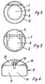
- the filler neck according to the invention consists of an inner tube 1 carrying the filling material, which is surrounded by an outer tube 2, onto which the valve sacks to be filled can be plugged with their sack valve. A distance is left between the inner tube 1 and the outer tube 2, so that an intermediate space 3 is formed which can be ring-shaped according to FIG. 2 and crescent-shaped according to FIG.
- the outer tube 2 is slightly curved in the region of its free end and is provided with an obliquely downward-pointing outlet opening 4, which is formed by a cross section through the curvature and obliquely to the axis of the filler neck.
- the inner tube 1 ends in an opening 5 located opposite the outlet opening 4, which opening is formed by an oblique cut through the inner tube 1, which is guided such that the upper part of the opening 5 springs back relative to the lower part.
- the opening 5 is kept closed by a flap 6 which is in the region of the Upper part of the opening 5 arranged, horizontally and transversely to the axis of the filler neck axis 7 is pivotally mounted.
- the closure flap 6 lies with its own weight on the end face of the inner tube 1.
- the pivoting path of the closure flap 6 is limited by an adjustable stop 8 which, in the open position of the closure flap 6, bears against the inner wall of the outer tube 2.
- the intermediate space 3 is provided with a suction connection 4 b and is closed at the end in its lower area 4 a in order to prevent the entry of filling material into the suction area.
- this closure results from a non-coaxial arrangement of the inner tube 2.
- the longitudinal axes of the two tubes are offset such that in the lower region of the filler neck the outer wall of the inner tube 1 is connected to the inner wall of the outer tube 2 Facility is coming.
- the embodiment according to FIG. 4 is based on a filler neck made of a hollow profile 9, which has an approximately rectangular cross section and is divided into two cavities 11 and 12 by a partition wall 10. While one cavity 11 is used to guide the flow of the filling material, the other cavity 12 is used to extract the air displaced from the valve bags when they are filled.
- the closure flap 7 is advantageously articulated here by means of a fork joint 13.
- the closure flap 6 Due to the inclined position of the closure flap 6, a gravity component holding the same in the closed position remains effective on it and can be overcome by the flow of the filling material.
- the closure flap 6 can act as an impact shield, which deflects the flow of the filling material downwards.
- the weight of the closure flap 6 also causes a backflow in the product flow, so that a desired pre-compaction, in particular air-containing product, is achieved.
Landscapes
- Engineering & Computer Science (AREA)
- Mechanical Engineering (AREA)
- Basic Packing Technique (AREA)
- Supply Of Fluid Materials To The Packaging Location (AREA)
Claims (1)
- Tubulure de remplissage pour machines de remplissage de sacs à valve , avec un tube extérieur (2), sur lequel les sacs à valve à remplir sont susceptibles d'être emboîtés avec leur ouverture de valve, et un tube intérieur (1), disposé dans le tube extérieur (2), pour assurer le guidage du produit de remplissage ainsi qu'avec un dispositif (6) destiné à obturer le tube intérieur, caractérisé en ce que le tube extérieur (2) est pourvu, à son extrémité libre, d'une ouverture de sortie (4) tournée obliquement vers le bas, en ce que le tube intérieur (1) présente une ouverture de sortie (5), en retrait par rapport à l'ouverture de sortie (4) et tournée obliquement vers le haut, en ce que l'ouverture de sortie (5) du tube intérieur (1) est pourvue d'un volet d'obturation (6), restant en position de fermeture du fait de l'effet de la pesanteur et susceptible d'être pivoté en position d'ouverture par le courant de produit de remplissage, en ce que le volet d'obturation (6) est pourvu d'une butée (8) réglable, venant buter à la paroi intérieure du tube extérieur (2) lorsque le volet (6) est dans la position d'ouverture, en vue de limiter son angle d'ouverture, et en ce que le volet de fermeture forme, lorsqu'il est dans sa position ouverte, une surface de guidage pour dévier le courant de produit de remplissage.
Priority Applications (1)
| Application Number | Priority Date | Filing Date | Title |
|---|---|---|---|
| AT90125633T ATE98588T1 (de) | 1990-01-13 | 1990-12-28 | Fuellstutzen fuer fuellmaschinen zum fuellen von ventilsaecken. |
Applications Claiming Priority (2)
| Application Number | Priority Date | Filing Date | Title |
|---|---|---|---|
| DE9000346U DE9000346U1 (de) | 1990-01-13 | 1990-01-13 | Füllstutzen für Füllmaschinen zum Füllen von Ventilsäcken |
| DE9000346U | 1990-01-13 |
Publications (2)
| Publication Number | Publication Date |
|---|---|
| EP0438794A1 EP0438794A1 (fr) | 1991-07-31 |
| EP0438794B1 true EP0438794B1 (fr) | 1993-12-15 |
Family
ID=6850008
Family Applications (1)
| Application Number | Title | Priority Date | Filing Date |
|---|---|---|---|
| EP90125633A Expired - Lifetime EP0438794B1 (fr) | 1990-01-13 | 1990-12-28 | Tuyère de remplissage pour machines de remplissage pour remplir des sacs à valve |
Country Status (3)
| Country | Link |
|---|---|
| EP (1) | EP0438794B1 (fr) |
| AT (1) | ATE98588T1 (fr) |
| DE (2) | DE9000346U1 (fr) |
Families Citing this family (1)
| Publication number | Priority date | Publication date | Assignee | Title |
|---|---|---|---|---|
| DE4103945C1 (en) * | 1991-02-09 | 1992-05-27 | Natronag Gesellschaft Fuer Verpackungssysteme Mbh, 3380 Goslar, De | Bag filling machine with tube for bag valve - has tube shutter with stop part pulled by cable against tube mouth |
Family Cites Families (3)
| Publication number | Priority date | Publication date | Assignee | Title |
|---|---|---|---|---|
| US3815629A (en) * | 1971-07-26 | 1974-06-11 | J Oberholtzer | Sewer relief valve |
| DE3809593A1 (de) * | 1988-03-22 | 1989-10-12 | Greif Werk Masch | Fuellstutzen fuer maschinen, vorrichtungen oder dergleichen zum fuellen von ventilsaecken |
| US4887792A (en) * | 1988-10-06 | 1989-12-19 | Kuo Ping Song | Stop-check valve |
-
1990
- 1990-01-13 DE DE9000346U patent/DE9000346U1/de not_active Expired - Lifetime
- 1990-12-28 DE DE90125633T patent/DE59003891D1/de not_active Expired - Fee Related
- 1990-12-28 EP EP90125633A patent/EP0438794B1/fr not_active Expired - Lifetime
- 1990-12-28 AT AT90125633T patent/ATE98588T1/de active
Also Published As
| Publication number | Publication date |
|---|---|
| EP0438794A1 (fr) | 1991-07-31 |
| ATE98588T1 (de) | 1994-01-15 |
| DE59003891D1 (de) | 1994-01-27 |
| DE9000346U1 (de) | 1990-04-05 |
Similar Documents
| Publication | Publication Date | Title |
|---|---|---|
| DE69106304T2 (de) | Dosiervorrichtung für Abfüllmaschinen. | |
| EP3164338B1 (fr) | Bouchon verseur pour le manchon d'un jerrican ou d'un récipient quelconque pour le versement contrôlé vers plusieurs côtés | |
| CH617873A5 (fr) | ||
| DE3107966C2 (de) | Vorrichtung zum Entleeren eines aufrecht angeordneten Schüttgut-Rundsilos | |
| EP0051117A1 (fr) | Sac à valve pour des produits poudreux | |
| DE4101257A1 (de) | Rohrpoststation | |
| EP0438794A1 (fr) | Tuyère de remplissage pour machines de remplissage pour remplir des sacs à valve | |
| DE9110905U1 (de) | Verschäumer-Sprühkopf | |
| EP1495965A2 (fr) | Machine verticale de fabrication de sacs tubulaires | |
| EP0340315A1 (fr) | Procédé et appareil pour amener des sacs à un poste de remplissage | |
| DE2233335A1 (de) | Absperrmechanismus an einem abflussrohr bei saemaschinen | |
| EP1890945A1 (fr) | Systeme de fermeture pour gourde | |
| EP0003132B1 (fr) | Couvercle pour un récipient | |
| DE102020129774A1 (de) | Vorrichtung zur Förderung und Reinigung von Kleinteilen mit einem offenen Hohlraum | |
| DE29502128U1 (de) | Flachbeutelmaschine | |
| DE19642969C1 (de) | Dosiereinrichtung für ein mit einer Ventilklappe versehenes Dosierrohr | |
| DE10119430C1 (de) | Müllbehälter mit Sekundärdeckel | |
| DE4103945C1 (en) | Bag filling machine with tube for bag valve - has tube shutter with stop part pulled by cable against tube mouth | |
| DE3929706A1 (de) | Fuellstutzen fuer fuellrohr zum befuellen von ventilsaecken | |
| EP1232947B1 (fr) | Dispositif de coupe d'un courant de matériau pulvérulent | |
| DE950358C (de) | Vorrichtung zum Entfalten eines auf eine Foerderschnecke einer Abfuellvorrichtung aufzuschiebenden Faltbeutels | |
| EP1136362B1 (fr) | Dispositif de remplissage pour matières en vrac | |
| DE19631258A1 (de) | Vertikale Schlauchbeutelmaschine und Verfahren zur Beschleunigung einer Produktportion in einer vertikalen Schlauchbeutelmaschine | |
| EP0108310B1 (fr) | Dispositif de remplissage pour sacs | |
| DE3439473A1 (de) | Vorrichtung zum aufstecken von zu fuellenden ventilsaecken auf den oder die fuellstutzen einer packmaschine |
Legal Events
| Date | Code | Title | Description |
|---|---|---|---|
| PUAI | Public reference made under article 153(3) epc to a published international application that has entered the european phase |
Free format text: ORIGINAL CODE: 0009012 |
|
| AK | Designated contracting states |
Kind code of ref document: A1 Designated state(s): AT BE CH DE ES FR GB IT LI LU NL |
|
| 17P | Request for examination filed |
Effective date: 19920121 |
|
| 17Q | First examination report despatched |
Effective date: 19920916 |
|
| GRAA | (expected) grant |
Free format text: ORIGINAL CODE: 0009210 |
|
| AK | Designated contracting states |
Kind code of ref document: B1 Designated state(s): AT BE CH DE ES FR GB IT LI LU NL |
|
| PG25 | Lapsed in a contracting state [announced via postgrant information from national office to epo] |
Ref country code: IT Free format text: LAPSE BECAUSE OF FAILURE TO SUBMIT A TRANSLATION OF THE DESCRIPTION OR TO PAY THE FEE WITHIN THE PRE;WARNING: LAPSES OF ITALIAN PATENTS WITH EFFECTIVE DATE BEFORE 2007 MAY HAVE OCCURRED AT ANY TIME BEFORE 2007. THE CORRECT EFFECTIVE DATE MAY BE DIFFERENT FROM THE ONE RECORDED.SCRIBED TIME-LIMIT Effective date: 19931215 Ref country code: FR Effective date: 19931215 Ref country code: GB Effective date: 19931215 Ref country code: NL Effective date: 19931215 Ref country code: BE Effective date: 19931215 Ref country code: ES Free format text: THE PATENT HAS BEEN ANNULLED BY A DECISION OF A NATIONAL AUTHORITY Effective date: 19931215 |
|
| REF | Corresponds to: |
Ref document number: 98588 Country of ref document: AT Date of ref document: 19940115 Kind code of ref document: T |
|
| PG25 | Lapsed in a contracting state [announced via postgrant information from national office to epo] |
Ref country code: AT Effective date: 19931228 |
|
| PG25 | Lapsed in a contracting state [announced via postgrant information from national office to epo] |
Ref country code: LU Free format text: LAPSE BECAUSE OF NON-PAYMENT OF DUE FEES Effective date: 19931231 Ref country code: LI Effective date: 19931231 Ref country code: CH Effective date: 19931231 |
|
| REF | Corresponds to: |
Ref document number: 59003891 Country of ref document: DE Date of ref document: 19940127 |
|
| EN | Fr: translation not filed | ||
| NLV1 | Nl: lapsed or annulled due to failure to fulfill the requirements of art. 29p and 29m of the patents act | ||
| GBV | Gb: ep patent (uk) treated as always having been void in accordance with gb section 77(7)/1977 [no translation filed] |
Effective date: 19931215 |
|
| REG | Reference to a national code |
Ref country code: CH Ref legal event code: PL |
|
| PLBE | No opposition filed within time limit |
Free format text: ORIGINAL CODE: 0009261 |
|
| STAA | Information on the status of an ep patent application or granted ep patent |
Free format text: STATUS: NO OPPOSITION FILED WITHIN TIME LIMIT |
|
| 26N | No opposition filed | ||
| PGFP | Annual fee paid to national office [announced via postgrant information from national office to epo] |
Ref country code: DE Payment date: 19970129 Year of fee payment: 7 |
|
| PG25 | Lapsed in a contracting state [announced via postgrant information from national office to epo] |
Ref country code: DE Free format text: LAPSE BECAUSE OF NON-PAYMENT OF DUE FEES Effective date: 19980901 |