EP0438802A1 - Procédé de contrôle d'un four - Google Patents
Procédé de contrôle d'un four Download PDFInfo
- Publication number
- EP0438802A1 EP0438802A1 EP90125698A EP90125698A EP0438802A1 EP 0438802 A1 EP0438802 A1 EP 0438802A1 EP 90125698 A EP90125698 A EP 90125698A EP 90125698 A EP90125698 A EP 90125698A EP 0438802 A1 EP0438802 A1 EP 0438802A1
- Authority
- EP
- European Patent Office
- Prior art keywords
- piston
- mass
- blank
- furnace
- time
- Prior art date
- Legal status (The legal status is an assumption and is not a legal conclusion. Google has not performed a legal analysis and makes no representation as to the accuracy of the status listed.)
- Granted
Links
- 238000000034 method Methods 0.000 title claims abstract description 24
- 230000033001 locomotion Effects 0.000 claims abstract description 15
- 238000000465 moulding Methods 0.000 claims description 18
- 238000010438 heat treatment Methods 0.000 claims description 14
- 239000011351 dental ceramic Substances 0.000 claims description 10
- 238000001514 detection method Methods 0.000 claims description 6
- 230000000754 repressing effect Effects 0.000 claims description 6
- 230000008859 change Effects 0.000 claims description 4
- 229910001092 metal group alloy Inorganic materials 0.000 claims description 3
- 230000009471 action Effects 0.000 claims description 2
- 238000005516 engineering process Methods 0.000 claims 2
- 230000001276 controlling effect Effects 0.000 claims 1
- 230000001419 dependent effect Effects 0.000 claims 1
- 230000001105 regulatory effect Effects 0.000 claims 1
- 238000007493 shaping process Methods 0.000 claims 1
- 239000000203 mixture Substances 0.000 abstract 1
- 238000003825 pressing Methods 0.000 description 15
- 230000002349 favourable effect Effects 0.000 description 7
- 238000004519 manufacturing process Methods 0.000 description 6
- 238000005266 casting Methods 0.000 description 4
- 238000007906 compression Methods 0.000 description 4
- 238000010304 firing Methods 0.000 description 4
- 239000000463 material Substances 0.000 description 3
- 238000005259 measurement Methods 0.000 description 3
- 239000000919 ceramic Substances 0.000 description 2
- 230000006835 compression Effects 0.000 description 2
- 230000007423 decrease Effects 0.000 description 2
- 230000004048 modification Effects 0.000 description 2
- 238000012986 modification Methods 0.000 description 2
- 230000015572 biosynthetic process Effects 0.000 description 1
- 239000005548 dental material Substances 0.000 description 1
- 238000013461 design Methods 0.000 description 1
- 238000011161 development Methods 0.000 description 1
- 230000018109 developmental process Effects 0.000 description 1
- 238000005429 filling process Methods 0.000 description 1
- 239000012778 molding material Substances 0.000 description 1
- 230000008569 process Effects 0.000 description 1
- 238000007789 sealing Methods 0.000 description 1
- 238000000926 separation method Methods 0.000 description 1
- 239000007787 solid Substances 0.000 description 1
- 238000005507 spraying Methods 0.000 description 1
- 230000036962 time dependent Effects 0.000 description 1
Images

Classifications
-
- A—HUMAN NECESSITIES
- A61—MEDICAL OR VETERINARY SCIENCE; HYGIENE
- A61C—DENTISTRY; APPARATUS OR METHODS FOR ORAL OR DENTAL HYGIENE
- A61C13/00—Dental prostheses; Making same
- A61C13/20—Methods or devices for soldering, casting, moulding or melting
-
- A—HUMAN NECESSITIES
- A61—MEDICAL OR VETERINARY SCIENCE; HYGIENE
- A61C—DENTISTRY; APPARATUS OR METHODS FOR ORAL OR DENTAL HYGIENE
- A61C13/00—Dental prostheses; Making same
- A61C13/20—Methods or devices for soldering, casting, moulding or melting
- A61C13/206—Injection moulding
Definitions
- the invention relates to a method according to the preamble of claim 1 and a furnace according to the preamble of claim 11.
- dental prostheses are known from DE-PS 26 32 846 and EP-A1-231 773.
- dental prosthetic items are manufactured in a kiln, in which the desired dental prosthetic material, for example a dental ceramic, is fired in a mold insert.
- a wax model is first created.
- a temperature-resistant mold insert is created, a casting channel being left free above the wax body - whether it is also by a wax body or by subsequent production.
- the wax is removed by heating, so that a molding space remains. This is followed by the casting channel, which serves as a pre-pressing space in the prior art mentioned.
- the mass serving as dental ceramic is then placed in this pre-pressing space, e.g. used in the form of a blank and softened by heating so that it gets into the mold space and takes on the shape of the desired dental prosthetic item.
- the mass was pressurized at an early stage and, for example, as was the case from AT-PS 157 210 it can be seen that the piston is weight-loaded. Basically nothing has changed in this method of exerting pressure, although the application of pressure with a pneumatic press cylinder has also been used, as can be seen from EP-A1-231 773.
- the furnace can be opened safely after the firing cycle by drawing conclusions about the temperature inside the muffle with the surprisingly simple measure of determining the change in the piston speed, at the same time using a suitably designed control unit.
- a temperature sensor can be replaced in a very simple manner, which would also always have to be connected separately in order to allow an exchange of the muffle together with the dental ceramic.
- the filling of the mold space can be optimized with the method according to the invention, regardless of the design and size of the mold and the corresponding tooth replacement part.
- the piston speed initially drops somewhat - assuming the same pressing pressure - but then decreases sharply as soon as the degree of filling is 100%, so that the flow and thus the lowering movement of the piston come to a standstill is coming.
- the furnace can now be switched off, which initially does not lead to any or no significant change in the temperature inside the mold insert due to the available heat capacities.
- the repressing time extends from the time of detection, the end of the constant piston speed, to the time of switch-off.
- the detection time can alternatively be defined as a time at which the piston speed falls below a predetermined value or as a time at which the piston speed becomes zero.
- the guide rod can be brought into the upper position and the muffle can be removed, so that the next dental ceramic can be started immediately.
- the time for producing the molding including the repressing time. If the mass of the crown and the blank to be produced is known, the lowering of the piston can serve as a measure of the degree of filling of the molding space. By using a suitable control unit, the values determined in this way can be automatically processed and a fully automatic control can be carried out.
- the piston speed can also be controlled by means of a pressure regulator. If the piston speed becomes too high at a preselected pressure, which creates the risk of excessive turbulence and bubble formation, the pressure can be reduced as an immediately effective measure and at the same time the heating output can be somewhat reduced. Reducing the heating power also reduces the piston speed, whereby the dead time due to the heat capacities must be taken into account.
- the maximum degree of filling can be determined simply by determining when the piston speed has dropped to zero or almost to zero. Furthermore, it is particularly favorable that the filling mass can be calculated exactly, although filling with standard blanks is also possible with different volumes of the dental prosthetic items (crowns, prostheses or the like).
- the resistance to deformation of the mass can be readily determined by the piston speed in relation to the force acting on the piston. If very differently designed dental prosthesis parts are to be produced, it may be advantageous to choose a lower pressing force for the production, for example, of a single gracefully designed crown. It is also possible to make the detection time dependent on the increase in the deformation resistance, since this increases strongly when the molding space is completely filled out.
- the oven temperature is automatically taken into account at the beginning of the filling cycle. If the furnace cools down more - if this takes a little longer - by inserting the muffle, the plasticization and thus the piston movement simply begins a little later.
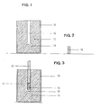
- the mold insert 12 has a recess which consists of a mold space 14 and a pre-compression space 16.
- the molding space 14 is formed by molding in in a manner known per se by means of a model of the tooth replacement part to be produced, such as the crown.
- the mold insert 12 consists of an investment material which is also temperature-resistant.
- the pre-pressing space 16 which has the shape of a cylinder tube, adjoins the molding space 14 at the top.
- the wall of the pre-pressing space 16 is formed by the mold insert 12 and has a smooth surface in the same way as is provided in the molding space 14.
- a blank 18 is shown, which has the shape of a solid cylinder and is designed in diameter so that it can be inserted into the pre-pressing space 16 according to FIG. 1 without difficulty.
- the volume of the blank 18 is determined so that it exceeds the volume of the mold space 14 and thus the dental prosthesis to be produced, with a certain safety margin.
- the blank 18 consists of a dental material, such as a pre-pressed dental ceramic, a metal alloy or a dental plastic. In a modification of the invention, it is provided that several crowns are manufactured at the same time. For this purpose, a majority of molding spaces 14 are expediently connected to the pre-pressing space 16 via corresponding casting channels, and the mass of the blank 18 is chosen to be correspondingly larger.
- a dental ceramic for the blank 18, it is advantageous if it has been pressed in a vacuum and then sintered, so that it is completely pore-free.
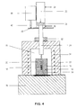
- the blank 18 has been introduced into the pre-pressing space 16, so that it rests on a casting channel 19, which is either formed from the material of the mold insert 12 or, as shown in FIG. 4, as a separate insert.
- a piston 20 is in the pre-pressing space 16 introduced, the diameter of which is selected so that it essentially seals against the walls of the pre-compression chamber 16, but the piston 20 should be easy to move.
- suitable temperature-resistant sealing devices known per se can be provided.
- the piston 20 is driven by a pressure cylinder, through which it can be lowered.
- the piston 20 bears against the pressure cylinder 22 via a guide rod 24, so that the unit consisting of muffle 10, mold insert 12 and piston 20 can be easily removed from the furnace.
- the guide rod 24 is fastened at its upper end to a drive piston 26, the diameter of which corresponds to the diameter of the pressure cylinder 22.
- a pressure line 28 or 30 is connected to the pressure cylinder 22 below and above the drive piston 26, with which the drive piston 26 and the guide rod 24 can be lowered and raised. By pressurizing the pressure line 28, pressure is then also exerted on the blank 18 via the piston 20, so that it can be pressed into the mold space 14 after softening. Since the guide rod 24 only bears against the piston 20, a precise alignment of the mold insert 12 is unnecessary. In addition, any canting errors are excluded in principle, because only vertically directed forces are transmitted.
- the guide rod 24 is guided in the top wall of a furnace 33 so that it can be moved, the guide being sealed by a seal 32, so that a vacuum can be generated in an interior 36 of the furnace in which the muffle 10 is inserted.
- the furnace 33 has a heating device 34, for example in the form of a heating spiral.
- the furnace 33 has a foundation 38. The hood consisting of the ceiling wall and the side walls can be lifted or opened from the foundation 38 and is sealed against this at the separation point.
- a control plate 40 which extends substantially horizontally and forms a support for a spring-loaded sensor rod 42 which is movably guided in a sensor 44 which in turn is attached to the pressure cylinder 22.
- a sensor 44 With the sensor 44, the position of the unit consisting of the drive piston 26, the guide rod 24 and the piston 20 can always be precisely detected.
- the lowering of the piston 20 can be controlled in the desired manner with a control unit 47 shown in FIG. 5.
- the sensor 44 is designed in a suitable manner. 5 the configuration in the form of a potentiometer 46 is provided, the resistance value of which is set to respond to the position of the piston 20 via the control plate 40.
- the potentiometer 46 has a very precisely maintained linearity, so that the detectable resistance value corresponds with good accuracy to the position of the piston 20.
- the sensor 44 is connected to the control unit 47.
- the control unit 47 is also connected to the heating device 34 via an amplifier 48, which can be designed as a thyristor device or as a relay device, the other connection of which is connected to ground.
- the control unit 47 can thus directly control the heating device 34 of the furnace 33.
- control unit 47 is connected to an input / output console 50, with which the desired firing times, the molding materials used, the desired operating mode (automatic or manual) and other parameters can be entered.
- a valve arrangement 52 is also provided for carrying out the method according to the invention, which in the embodiment shown has a lift valve 54 and a lowering valve 56.
- each valve is electrically connected to the control unit 47 and has corresponding control magnets 58 and 60, respectively.
- the lowering valve 56 is designed as a controllable throttle valve, the position of which is adjustable, so that the pressure in the pressure cylinder 22 can be adjusted in accordance with the action on the control magnet 60, which preferably has two coils.
- the control force 47 can be used to control the pressing force exerted by the piston 20 both in wide ranges and with a correspondingly fine resolution.
- the lowering valve 56 is connected to the pressure cylinder 22 via the pressure line 28, while the lift valve 54 is connected to the pressure cylinder 22 via the pressure line 30.
- the two pressure lines 28 and 30 are each connected to a throttle point 61 or 62, so that an uncomplicated pressure control can be provided in the pressure lines.
- the lift valve 54 is designed such that when the control magnet 58 responds, it causes the pressure line 30 to be pressurized and thus the piston 20 to be lifted. This occurs between the firing cycles, for example when the muffle 10 is to be removed.
- the valve arrangement 52 is connected to a pressure vessel 64, which is also connected to a pump 66, so that it is ensured that the inlet pressure for the valve arrangement 52 is always sufficient to be able to carry out the desired control operations.
- the type of pneumatic control can be carried out in a variety of other ways.
- the lift valve 54 can be replaced by a two-way valve which causes a pressure relief if it does not respond, so that the throttle point 62 can be omitted and the pressure line 30 is closed at this point.
- the function of the throttle point 61 can also be practically integrated into the lowering valve 56.
- the entire pneumatic system can be replaced by an electrical configuration of the pressure cylinder 22.
- the guide rod 24 is replaced by a corresponding drive spindle for the piston 20, and the current consumption of the driving motor for the drive spindle can be used as an additional pressure sensor in addition to the control plate 40 as a motion sensor.
- the piston 20 can also be pressurized in any other manner.
- the sensor 44 is designed as a pressure sensor. With this configuration, too, a movement parameter of the piston 20 can be detected by determining the increase in pressure shortly before the mold space 14 is completely filled with the mass. This increase in pressure corresponds to the decrease in advance speed described above, the output signal of the pressure sensor 44 also being fed to the control unit 47.
- the different configuration of the mold space or the different quantities of the mold can also be determined via the ratio of temperature and absolute pressure or change in the back pressure take the required mass into account.
- the pressure drop in the interior 36 of the furnace 33 can also be included in the automatic control.
- the desired post-pressing time and / or post-firing time can also be automatic both after the measured movement of the control plate, corresponding to the volume of the molding space 14 can be set or preselected via the input / output console.
- the piston 20 is equipped with a head which, due to its additional weight, exerts pressure on the molding even when the muffle 10 has already been removed from the furnace 33.
- the head provides an enlarged end face for contact with the lower end face of the guide rod 24, so that the centering of the muffle 10 in the furnace 33 becomes even less critical.
Landscapes
- Health & Medical Sciences (AREA)
- Oral & Maxillofacial Surgery (AREA)
- Dentistry (AREA)
- Epidemiology (AREA)
- Life Sciences & Earth Sciences (AREA)
- Animal Behavior & Ethology (AREA)
- General Health & Medical Sciences (AREA)
- Public Health (AREA)
- Veterinary Medicine (AREA)
- Dental Prosthetics (AREA)
- Crystals, And After-Treatments Of Crystals (AREA)
- Muffle Furnaces And Rotary Kilns (AREA)
- Control Of High-Frequency Heating Circuits (AREA)
- Electric Ovens (AREA)
- Moulds For Moulding Plastics Or The Like (AREA)
Priority Applications (1)
| Application Number | Priority Date | Filing Date | Title |
|---|---|---|---|
| AT90125698T ATE100694T1 (de) | 1990-01-26 | 1990-12-28 | Verfahren zum steuern eines ofens. |
Applications Claiming Priority (2)
| Application Number | Priority Date | Filing Date | Title |
|---|---|---|---|
| DE4002358A DE4002358C1 (en) | 1990-01-26 | 1990-01-26 | Oven control for dental material pressing and hardening - detects degree of filling of shaping space by speed of movement of piston in pressure cylinder |
| DE4002358 | 1990-01-26 |
Publications (2)
| Publication Number | Publication Date |
|---|---|
| EP0438802A1 true EP0438802A1 (fr) | 1991-07-31 |
| EP0438802B1 EP0438802B1 (fr) | 1994-01-26 |
Family
ID=6398874
Family Applications (1)
| Application Number | Title | Priority Date | Filing Date |
|---|---|---|---|
| EP90125698A Expired - Lifetime EP0438802B1 (fr) | 1990-01-26 | 1990-12-28 | Procédé de contrôle d'un four |
Country Status (5)
| Country | Link |
|---|---|
| EP (1) | EP0438802B1 (fr) |
| AT (1) | ATE100694T1 (fr) |
| AU (1) | AU617064B2 (fr) |
| CA (1) | CA2034893A1 (fr) |
| DE (2) | DE4002358C1 (fr) |
Cited By (14)
| Publication number | Priority date | Publication date | Assignee | Title |
|---|---|---|---|---|
| EP0935950A1 (fr) * | 1998-02-10 | 1999-08-18 | Tokuyama Corporation | Dispositif et procédé de moulage par pression |
| EP1038507A1 (fr) * | 1999-03-26 | 2000-09-27 | Ivoclar Ag | Procédé de contrôle d'un four |
| US6303059B1 (en) | 1999-03-26 | 2001-10-16 | Ivoclar A.G. | Method of controlling an oven |
| BE1014467A5 (fr) * | 1999-11-10 | 2003-11-04 | G C Dental Ind Corp | Procede de preparation de protheses dentaires. |
| DE10257208A1 (de) * | 2002-12-06 | 2004-07-08 | Ivoclar Vivadent Ag | Muffelsystem |
| DE10324404A1 (de) * | 2003-05-28 | 2004-12-30 | Dekema Dental-Keramiköfen GmbH | Verfahren zur Herstellung von Objekten zum Zahnersatz oder-teilersatz und Pressofen hierfür |
| WO2007107350A1 (fr) * | 2006-03-22 | 2007-09-27 | Dekema Dental-Keramiköfen GmbH | Four de cuisson dentaire pour prothèses dentaires ou parties de prothèses dentaires |
| EP1972303A1 (fr) * | 2007-03-20 | 2008-09-24 | Wegold Edelmetalle AG | Dispositif de compression d'un matériau dentaire destiné à la fabrication d'une prothèse dentaire ou d'une partie de prothèse dentaire |
| EP1978321A1 (fr) * | 2007-03-30 | 2008-10-08 | Ivoclar Vivadent AG | Détection de moufle |
| WO2012076134A1 (fr) * | 2010-12-09 | 2012-06-14 | Dekema Dental-Keramiköfen GmbH | Four de pressée pour prothèse dentaire ou prothèse dentaire partielle |
| CN102901356A (zh) * | 2011-07-25 | 2013-01-30 | 义获嘉伟瓦登特公司 | 牙科炉具 |
| EP2886080A1 (fr) * | 2013-12-20 | 2015-06-24 | Ivoclar Vivadent AG | Procédé de traitement d'un matériau dentaire, dispositif de réglage pour un four dentaire et four dentaire |
| EP3096100A1 (fr) * | 2015-05-22 | 2016-11-23 | Ivoclar Vivadent AG | Four de pressée dentaire |
| EP3321621A1 (fr) * | 2016-11-15 | 2018-05-16 | Ivoclar Vivadent AG | Système de four et de déblais des particules de verre et procédé de fonctionnement d'un four |
Families Citing this family (7)
| Publication number | Priority date | Publication date | Assignee | Title |
|---|---|---|---|---|
| DE4340200C2 (de) * | 1993-11-25 | 1998-07-23 | Dekema Dental Keramikoefen Gmb | Anordnung zur Wärmebehandlung von Gegenständen, insbesondere von Zahnersatz oder -teilersatz |
| US6252202B1 (en) | 1998-02-10 | 2001-06-26 | Jeneric/Pentron, Inc. | Furnace for heat treatment of dental materials |
| DE19844136B4 (de) * | 1998-09-25 | 2005-08-11 | Ivoclar Vivadent Ag | Ofen für die Herstellung von Zahnersatzteilen |
| DE10208801C1 (de) * | 2002-03-01 | 2003-06-12 | Horst-Juergen Heidenegger | Brennofen für das Brennen presskeramischen Zahnersatzes |
| DE10327892B3 (de) * | 2003-06-20 | 2004-12-02 | Volker Merten | Vorrichtung zum Pressen von dentalkeramischer Masse für die Herstellung von Zahnersatz, wie Kronen, Brücken, Inlays , sowie eine Kolben-Muffelanordnung für eine solche Vorrichtung |
| DE102006050830A1 (de) * | 2006-10-27 | 2008-04-30 | Ivoclar Vivadent Ag | Verfahren zum Betrieb eines Pressofens sowie Pressofen |
| US11376104B2 (en) | 2013-12-20 | 2022-07-05 | Ivoclar Vivadent Ag | Method for processing a dental material and a dental furnace |
Citations (3)
| Publication number | Priority date | Publication date | Assignee | Title |
|---|---|---|---|---|
| DE2264247A1 (de) * | 1972-12-30 | 1974-07-11 | Krupp Gmbh | Verfahren zur herstellung von formlingen |
| EP0231773A1 (fr) * | 1986-01-17 | 1987-08-12 | Etablissement Dentaire IVOCLAR | Procédé et chauffe pour fabriquer des dents artificielles |
| DE3831539A1 (de) * | 1988-09-16 | 1990-03-22 | Kaltenbach & Voigt | Steuerung fuer dentaloefen, insbesondere mikroprozessorgesteuerte vorwaermoefen |
Family Cites Families (1)
| Publication number | Priority date | Publication date | Assignee | Title |
|---|---|---|---|---|
| AT352863B (de) * | 1975-07-31 | 1979-10-10 | Pfaffenbauer Ludwig Ing | Vakuumbrennofen, insbesondere fuer dentalkeramische zwecke |
-
1990
- 1990-01-26 DE DE4002358A patent/DE4002358C1/de not_active Expired - Fee Related
- 1990-12-28 AT AT90125698T patent/ATE100694T1/de not_active IP Right Cessation
- 1990-12-28 DE DE90125698T patent/DE59004425D1/de not_active Expired - Lifetime
- 1990-12-28 EP EP90125698A patent/EP0438802B1/fr not_active Expired - Lifetime
-
1991
- 1991-01-17 AU AU69424/91A patent/AU617064B2/en not_active Ceased
- 1991-01-24 CA CA002034893A patent/CA2034893A1/fr not_active Abandoned
Patent Citations (3)
| Publication number | Priority date | Publication date | Assignee | Title |
|---|---|---|---|---|
| DE2264247A1 (de) * | 1972-12-30 | 1974-07-11 | Krupp Gmbh | Verfahren zur herstellung von formlingen |
| EP0231773A1 (fr) * | 1986-01-17 | 1987-08-12 | Etablissement Dentaire IVOCLAR | Procédé et chauffe pour fabriquer des dents artificielles |
| DE3831539A1 (de) * | 1988-09-16 | 1990-03-22 | Kaltenbach & Voigt | Steuerung fuer dentaloefen, insbesondere mikroprozessorgesteuerte vorwaermoefen |
Non-Patent Citations (1)
| Title |
|---|
| PATENT ABSTRACTS OF JAPAN, Band 13, Nr. 318 (M-852)[3666], 19. Juli 1989; & JP-A-1 104 500 (HITACHI METALS LTD) 21-04-1989 * |
Cited By (36)
| Publication number | Priority date | Publication date | Assignee | Title |
|---|---|---|---|---|
| EP0935950A1 (fr) * | 1998-02-10 | 1999-08-18 | Tokuyama Corporation | Dispositif et procédé de moulage par pression |
| EP1038507A1 (fr) * | 1999-03-26 | 2000-09-27 | Ivoclar Ag | Procédé de contrôle d'un four |
| DE19913891A1 (de) * | 1999-03-26 | 2000-09-28 | Ivoclar Ag Schaan | Verfahren zum Steuern eines Ofens |
| JP2000316882A (ja) * | 1999-03-26 | 2000-11-21 | Ivoclar Ag | 燃焼窯の制御方法 |
| US6303059B1 (en) | 1999-03-26 | 2001-10-16 | Ivoclar A.G. | Method of controlling an oven |
| DE19913891C2 (de) * | 1999-03-26 | 2003-03-27 | Ivoclar Vivadent Ag | Verfahren zur Herstellung von Zahnersatz |
| BE1014467A5 (fr) * | 1999-11-10 | 2003-11-04 | G C Dental Ind Corp | Procede de preparation de protheses dentaires. |
| DE10257208B4 (de) * | 2002-12-06 | 2008-02-21 | Ivoclar Vivadent Ag | Muffelsystem |
| DE10257208A1 (de) * | 2002-12-06 | 2004-07-08 | Ivoclar Vivadent Ag | Muffelsystem |
| US7118085B2 (en) | 2002-12-06 | 2006-10-10 | Ivoclar Vivadent Ag | Retort system |
| DE10324404A1 (de) * | 2003-05-28 | 2004-12-30 | Dekema Dental-Keramiköfen GmbH | Verfahren zur Herstellung von Objekten zum Zahnersatz oder-teilersatz und Pressofen hierfür |
| WO2007107350A1 (fr) * | 2006-03-22 | 2007-09-27 | Dekema Dental-Keramiköfen GmbH | Four de cuisson dentaire pour prothèses dentaires ou parties de prothèses dentaires |
| EP1972303A1 (fr) * | 2007-03-20 | 2008-09-24 | Wegold Edelmetalle AG | Dispositif de compression d'un matériau dentaire destiné à la fabrication d'une prothèse dentaire ou d'une partie de prothèse dentaire |
| EP1978321A1 (fr) * | 2007-03-30 | 2008-10-08 | Ivoclar Vivadent AG | Détection de moufle |
| US8232506B2 (en) | 2007-03-30 | 2012-07-31 | Ivoclar Vivadent Ag | Dental firing furnace |
| WO2012076134A1 (fr) * | 2010-12-09 | 2012-06-14 | Dekema Dental-Keramiköfen GmbH | Four de pressée pour prothèse dentaire ou prothèse dentaire partielle |
| US9022763B2 (en) | 2010-12-09 | 2015-05-05 | Dekema Dental-Keramikofen Gmbh | Press furnace for a denture or partial denture |
| CN102901356B (zh) * | 2011-07-25 | 2015-05-13 | 义获嘉伟瓦登特公司 | 牙科炉具 |
| CN102901356A (zh) * | 2011-07-25 | 2013-01-30 | 义获嘉伟瓦登特公司 | 牙科炉具 |
| EP3178441A1 (fr) * | 2013-12-20 | 2017-06-14 | Ivoclar Vivadent AG | Procédé de traitement d'un matériau dentaire, dispositif de réglage pour un four dentaire et four dentaire |
| WO2015091779A1 (fr) * | 2013-12-20 | 2015-06-25 | Ivoclar Vivadent Ag | Procédé de façonnage d'un matériau dentaire, système de réglage d'un four dentaire et four dentaire |
| CN105658173A (zh) * | 2013-12-20 | 2016-06-08 | 义获嘉伟瓦登特公司 | 加工牙科材料的方法、牙科用炉的调节装置以及牙科用炉 |
| KR20160100293A (ko) * | 2013-12-20 | 2016-08-23 | 이보클라 비바덴트 아게 | 치과 재료를 가공하는 방법, 치과용 노의 조절 장치, 및 치과용 노 |
| KR102339373B1 (ko) * | 2013-12-20 | 2021-12-16 | 이보클라 비바덴트 아게 | 치과 재료를 가공하는 방법, 치과용 노의 조절 장치, 및 치과용 노 |
| CN105658173B (zh) * | 2013-12-20 | 2018-04-20 | 义获嘉伟瓦登特公司 | 加工牙科材料的方法、牙科用炉的调节装置以及牙科用炉 |
| JP2017500140A (ja) * | 2013-12-20 | 2017-01-05 | イボクラール ビバデント アクチェンゲゼルシャフト | 歯科材料を処理する方法、歯科用窯の制御装置、ならびに歯科用窯 |
| EP2886080A1 (fr) * | 2013-12-20 | 2015-06-24 | Ivoclar Vivadent AG | Procédé de traitement d'un matériau dentaire, dispositif de réglage pour un four dentaire et four dentaire |
| WO2016188901A1 (fr) * | 2015-05-22 | 2016-12-01 | Ivoclar Vivadent Ag | Four de pressée pour laboratoire dentaire |
| CN107636411A (zh) * | 2015-05-22 | 2018-01-26 | 伊沃克拉尔维瓦登特股份公司 | 牙科压制炉 |
| US10441390B2 (en) | 2015-05-22 | 2019-10-15 | Ivoclar Vivadent Ag | Dental press furnace |
| CN107636411B (zh) * | 2015-05-22 | 2019-10-25 | 伊沃克拉尔维瓦登特股份公司 | 牙科压制炉 |
| EP3096100A1 (fr) * | 2015-05-22 | 2016-11-23 | Ivoclar Vivadent AG | Four de pressée dentaire |
| EP3321621A1 (fr) * | 2016-11-15 | 2018-05-16 | Ivoclar Vivadent AG | Système de four et de déblais des particules de verre et procédé de fonctionnement d'un four |
| WO2018091457A1 (fr) * | 2016-11-15 | 2018-05-24 | Ivoclar Vivadent Ag | Agencement d'un four et de débris de particules de verre et procédé permettant de faire fonctionner un four |
| US20200072552A1 (en) * | 2016-11-15 | 2020-03-05 | Ivoclar Vivadent Ag | Arrangement Of A Furnace And Of Bulk Material Of Glass Particles As Well As Method For Operating A Furnace |
| US11808520B2 (en) * | 2016-11-15 | 2023-11-07 | Ivoclar Vivadent Ag | Arrangement of a furnace and of bulk material of glass particles as well as method for operating a furnace |
Also Published As
| Publication number | Publication date |
|---|---|
| DE59004425D1 (de) | 1994-03-10 |
| AU617064B2 (en) | 1991-11-14 |
| AU6942491A (en) | 1991-08-01 |
| ATE100694T1 (de) | 1994-02-15 |
| EP0438802B1 (fr) | 1994-01-26 |
| CA2034893A1 (fr) | 1991-07-27 |
| DE4002358C1 (en) | 1991-10-24 |
Similar Documents
| Publication | Publication Date | Title |
|---|---|---|
| EP0438802B1 (fr) | Procédé de contrôle d'un four | |
| EP3178441B1 (fr) | Procédé de traitement d'un matériau dentaire, dispositif de réglage pour un four dentaire et four dentaire | |
| DE2253506C3 (de) | Regeleinrichtung für die Einspritzeinheit einer Schnecken-Spritzgießmaschine | |
| EP2583811B2 (fr) | Procédé de quantification de basculements de procédés dans le cadre d'un processus d'injection d'une machine de moulage par injection | |
| EP0231773A1 (fr) | Procédé et chauffe pour fabriquer des dents artificielles | |
| EP2627281B1 (fr) | Four de pressée pour prothèse dentaire ou prothèse dentaire partielle | |
| DE4239558A1 (de) | Verfahren zur Unterdruck-Herstellung bei einer Druckgießmaschine | |
| WO2014090487A1 (fr) | Four dentaire | |
| DE2826060C3 (de) | Verfahren und Einrichtung zur Regelung einer NiederdruckgieSanlage | |
| DE102018122982B4 (de) | Verfahren und Vorrichtung zur Herstellung von Hohlkörpern aus spritzgegossenem Kunststoffmaterial | |
| EP1516687B1 (fr) | Procédé de coulée sous pression sous vide ou de moulage par injection sous vide | |
| EP1915973B1 (fr) | Procédé de fonctionnement d'un four à pression ainsi que four à pression | |
| AT514847B1 (de) | Verfahren zur Bestimmung eines Sollwerts für einen Einstellparameter | |
| DE3040762A1 (de) | Verfahren und vorrichtung zur einstellung der masse von posten thermoplastischen materials | |
| DE1584543C3 (de) | Regeleinrichtung an Pressen zum Herstellen von Formungen gleicher Dichte und gleicher Abmessungen | |
| EP1584881A2 (fr) | Four de moulage par compression ainsi qu'un corps intermédiaire pour un four de moulage par compression et procédé de fonctionnement d'un four de moulage par compression | |
| DE19844136B4 (de) | Ofen für die Herstellung von Zahnersatzteilen | |
| EP3096100B1 (fr) | Four de pressée dentaire | |
| DE1298678B (de) | Giessanlage mit einer Einrichtung zur selbsttaetigen Einbringung gleicher Volumina schmelzfluessigen Metalls | |
| DE68902061T2 (de) | Glasformmaschine. | |
| DE102006004433C5 (de) | Pressofen | |
| EP3321621A1 (fr) | Système de four et de déblais des particules de verre et procédé de fonctionnement d'un four | |
| EP1972303A1 (fr) | Dispositif de compression d'un matériau dentaire destiné à la fabrication d'une prothèse dentaire ou d'une partie de prothèse dentaire | |
| DE4103408A1 (de) | Vorrichtung und verfahren zur herstellung von masshaltigen formkoerpern aus pastoesen massen | |
| DE1729382B2 (de) | Einrichtung zur steuerung einer spritzgiessmaschine fuer formbare massen |
Legal Events
| Date | Code | Title | Description |
|---|---|---|---|
| PUAI | Public reference made under article 153(3) epc to a published international application that has entered the european phase |
Free format text: ORIGINAL CODE: 0009012 |
|
| AK | Designated contracting states |
Kind code of ref document: A1 Designated state(s): AT CH DE FR GB IT LI SE |
|
| 17P | Request for examination filed |
Effective date: 19910803 |
|
| 17Q | First examination report despatched |
Effective date: 19921229 |
|
| GRAA | (expected) grant |
Free format text: ORIGINAL CODE: 0009210 |
|
| ITF | It: translation for a ep patent filed | ||
| AK | Designated contracting states |
Kind code of ref document: B1 Designated state(s): AT CH DE FR GB IT LI SE |
|
| REF | Corresponds to: |
Ref document number: 100694 Country of ref document: AT Date of ref document: 19940215 Kind code of ref document: T |
|
| REF | Corresponds to: |
Ref document number: 59004425 Country of ref document: DE Date of ref document: 19940310 |
|
| ET | Fr: translation filed | ||
| GBT | Gb: translation of ep patent filed (gb section 77(6)(a)/1977) |
Effective date: 19940217 |
|
| PLBE | No opposition filed within time limit |
Free format text: ORIGINAL CODE: 0009261 |
|
| STAA | Information on the status of an ep patent application or granted ep patent |
Free format text: STATUS: NO OPPOSITION FILED WITHIN TIME LIMIT |
|
| 26N | No opposition filed | ||
| EAL | Se: european patent in force in sweden |
Ref document number: 90125698.2 |
|
| ITTA | It: last paid annual fee | ||
| REG | Reference to a national code |
Ref country code: GB Ref legal event code: IF02 |
|
| PGFP | Annual fee paid to national office [announced via postgrant information from national office to epo] |
Ref country code: AT Payment date: 20091217 Year of fee payment: 20 Ref country code: CH Payment date: 20091222 Year of fee payment: 20 Ref country code: SE Payment date: 20091218 Year of fee payment: 20 |
|
| PGFP | Annual fee paid to national office [announced via postgrant information from national office to epo] |
Ref country code: FR Payment date: 20100105 Year of fee payment: 20 Ref country code: GB Payment date: 20091221 Year of fee payment: 20 Ref country code: IT Payment date: 20091224 Year of fee payment: 20 |
|
| PGFP | Annual fee paid to national office [announced via postgrant information from national office to epo] |
Ref country code: DE Payment date: 20100222 Year of fee payment: 20 |
|
| REG | Reference to a national code |
Ref country code: CH Ref legal event code: PL |
|
| REG | Reference to a national code |
Ref country code: GB Ref legal event code: PE20 Expiry date: 20101227 |
|
| EUG | Se: european patent has lapsed | ||
| PG25 | Lapsed in a contracting state [announced via postgrant information from national office to epo] |
Ref country code: GB Free format text: LAPSE BECAUSE OF EXPIRATION OF PROTECTION Effective date: 20101227 |
|
| PG25 | Lapsed in a contracting state [announced via postgrant information from national office to epo] |
Ref country code: DE Free format text: LAPSE BECAUSE OF EXPIRATION OF PROTECTION Effective date: 20101228 |