EP0438804A1 - Dispositif de commande de suralimentation par turbocompresseur - Google Patents
Dispositif de commande de suralimentation par turbocompresseur Download PDFInfo
- Publication number
- EP0438804A1 EP0438804A1 EP90125703A EP90125703A EP0438804A1 EP 0438804 A1 EP0438804 A1 EP 0438804A1 EP 90125703 A EP90125703 A EP 90125703A EP 90125703 A EP90125703 A EP 90125703A EP 0438804 A1 EP0438804 A1 EP 0438804A1
- Authority
- EP
- European Patent Office
- Prior art keywords
- exhaust gas
- turbine
- gas flow
- negative pressure
- suction
- Prior art date
- Legal status (The legal status is an assumption and is not a legal conclusion. Google has not performed a legal analysis and makes no representation as to the accuracy of the status listed.)
- Granted
Links
Images


Classifications
-
- F—MECHANICAL ENGINEERING; LIGHTING; HEATING; WEAPONS; BLASTING
- F02—COMBUSTION ENGINES; HOT-GAS OR COMBUSTION-PRODUCT ENGINE PLANTS
- F02B—INTERNAL-COMBUSTION PISTON ENGINES; COMBUSTION ENGINES IN GENERAL
- F02B37/00—Engines characterised by provision of pumps driven at least for part of the time by exhaust
-
- F—MECHANICAL ENGINEERING; LIGHTING; HEATING; WEAPONS; BLASTING
- F01—MACHINES OR ENGINES IN GENERAL; ENGINE PLANTS IN GENERAL; STEAM ENGINES
- F01N—GAS-FLOW SILENCERS OR EXHAUST APPARATUS FOR MACHINES OR ENGINES IN GENERAL; GAS-FLOW SILENCERS OR EXHAUST APPARATUS FOR INTERNAL-COMBUSTION ENGINES
- F01N1/00—Silencing apparatus characterised by method of silencing
- F01N1/24—Silencing apparatus characterised by method of silencing by using sound-absorbing materials
-
- F—MECHANICAL ENGINEERING; LIGHTING; HEATING; WEAPONS; BLASTING
- F01—MACHINES OR ENGINES IN GENERAL; ENGINE PLANTS IN GENERAL; STEAM ENGINES
- F01N—GAS-FLOW SILENCERS OR EXHAUST APPARATUS FOR MACHINES OR ENGINES IN GENERAL; GAS-FLOW SILENCERS OR EXHAUST APPARATUS FOR INTERNAL-COMBUSTION ENGINES
- F01N3/00—Exhaust or silencing apparatus having means for purifying, rendering innocuous, or otherwise treating exhaust
- F01N3/08—Exhaust or silencing apparatus having means for purifying, rendering innocuous, or otherwise treating exhaust for rendering innocuous
- F01N3/10—Exhaust or silencing apparatus having means for purifying, rendering innocuous, or otherwise treating exhaust for rendering innocuous by thermal or catalytic conversion of noxious components of exhaust
- F01N3/24—Exhaust or silencing apparatus having means for purifying, rendering innocuous, or otherwise treating exhaust for rendering innocuous by thermal or catalytic conversion of noxious components of exhaust characterised by constructional aspects of converting apparatus
- F01N3/28—Construction of catalytic reactors
- F01N3/2882—Catalytic reactors combined or associated with other devices, e.g. exhaust silencers or other exhaust purification devices
-
- F—MECHANICAL ENGINEERING; LIGHTING; HEATING; WEAPONS; BLASTING
- F01—MACHINES OR ENGINES IN GENERAL; ENGINE PLANTS IN GENERAL; STEAM ENGINES
- F01N—GAS-FLOW SILENCERS OR EXHAUST APPARATUS FOR MACHINES OR ENGINES IN GENERAL; GAS-FLOW SILENCERS OR EXHAUST APPARATUS FOR INTERNAL-COMBUSTION ENGINES
- F01N5/00—Exhaust or silencing apparatus combined or associated with devices profiting by exhaust energy
- F01N5/04—Exhaust or silencing apparatus combined or associated with devices profiting by exhaust energy the devices using kinetic energy
-
- F—MECHANICAL ENGINEERING; LIGHTING; HEATING; WEAPONS; BLASTING
- F02—COMBUSTION ENGINES; HOT-GAS OR COMBUSTION-PRODUCT ENGINE PLANTS
- F02B—INTERNAL-COMBUSTION PISTON ENGINES; COMBUSTION ENGINES IN GENERAL
- F02B37/00—Engines characterised by provision of pumps driven at least for part of the time by exhaust
- F02B37/007—Engines characterised by provision of pumps driven at least for part of the time by exhaust with exhaust-driven pumps arranged in parallel, e.g. at least one pump supplying alternatively
-
- F—MECHANICAL ENGINEERING; LIGHTING; HEATING; WEAPONS; BLASTING
- F04—POSITIVE - DISPLACEMENT MACHINES FOR LIQUIDS; PUMPS FOR LIQUIDS OR ELASTIC FLUIDS
- F04F—PUMPING OF FLUID BY DIRECT CONTACT OF ANOTHER FLUID OR BY USING INERTIA OF FLUID TO BE PUMPED; SIPHONS
- F04F5/00—Jet pumps, i.e. devices in which flow is induced by pressure drop caused by velocity of another fluid flow
- F04F5/14—Jet pumps, i.e. devices in which flow is induced by pressure drop caused by velocity of another fluid flow the inducing fluid being elastic fluid
- F04F5/16—Jet pumps, i.e. devices in which flow is induced by pressure drop caused by velocity of another fluid flow the inducing fluid being elastic fluid displacing elastic fluids
- F04F5/20—Jet pumps, i.e. devices in which flow is induced by pressure drop caused by velocity of another fluid flow the inducing fluid being elastic fluid displacing elastic fluids for evacuating
-
- F—MECHANICAL ENGINEERING; LIGHTING; HEATING; WEAPONS; BLASTING
- F01—MACHINES OR ENGINES IN GENERAL; ENGINE PLANTS IN GENERAL; STEAM ENGINES
- F01N—GAS-FLOW SILENCERS OR EXHAUST APPARATUS FOR MACHINES OR ENGINES IN GENERAL; GAS-FLOW SILENCERS OR EXHAUST APPARATUS FOR INTERNAL-COMBUSTION ENGINES
- F01N2230/00—Combination of silencers and other devices
- F01N2230/04—Catalytic converters
-
- F—MECHANICAL ENGINEERING; LIGHTING; HEATING; WEAPONS; BLASTING
- F02—COMBUSTION ENGINES; HOT-GAS OR COMBUSTION-PRODUCT ENGINE PLANTS
- F02B—INTERNAL-COMBUSTION PISTON ENGINES; COMBUSTION ENGINES IN GENERAL
- F02B1/00—Engines characterised by fuel-air mixture compression
- F02B1/02—Engines characterised by fuel-air mixture compression with positive ignition
- F02B1/04—Engines characterised by fuel-air mixture compression with positive ignition with fuel-air mixture admission into cylinder
-
- Y—GENERAL TAGGING OF NEW TECHNOLOGICAL DEVELOPMENTS; GENERAL TAGGING OF CROSS-SECTIONAL TECHNOLOGIES SPANNING OVER SEVERAL SECTIONS OF THE IPC; TECHNICAL SUBJECTS COVERED BY FORMER USPC CROSS-REFERENCE ART COLLECTIONS [XRACs] AND DIGESTS
- Y02—TECHNOLOGIES OR APPLICATIONS FOR MITIGATION OR ADAPTATION AGAINST CLIMATE CHANGE
- Y02T—CLIMATE CHANGE MITIGATION TECHNOLOGIES RELATED TO TRANSPORTATION
- Y02T10/00—Road transport of goods or passengers
- Y02T10/10—Internal combustion engine [ICE] based vehicles
- Y02T10/12—Improving ICE efficiencies
Definitions
- the present invention relates to an apparatus for driving a turbo supercharger in high efficiency in an internal combustion engine.
- a system or an apparatus for rotating an exhaust gas turbine by exhaust gas energy to drive a supercharger and prepressurizing suction gas is known. Recently, the systems have been frequently employed in automotive engines.
- the conventional turbo supercharger normally employs only one stage of a centrifugal turbine to convert kinetic energy produced by feeding part or all of exhaust gas discharged from the combustion chamber of an engine to an exhaust gas turbine, into rotary motion as the power of the supercharging turbine.
- the supercharging turbine prepressurizes suction gas and charges vaporized fuel enhanced in its density to a combustion chamber.
- the present inventor has repeatedly studies the advantages of driving a supercharger with exhaust gas energy. Then, a conclusion that the driving system is malfunctioned only by the kinetic energy of the exhaust gas flow outputted from a combustion chamber.
- the exhaust gas energy of high speed exceeding a sonic speed can be utilized as it is, the problem can be relatively reduced, but since large load resistance is incorporated at the rear in fact, the energy cannot be sufficiently utilized.
- the exhaust gas efficiency equivalent to that having no other resistances such as catalyst, silencer, etc. this problem can be solved. If the exhaust gas efficiency can be improved. the problem of the stay of the heat can be alleviated, and the problem of the heat can be eliminated.
- the present invention has been accomplished with such circumstances in view. It is an object of the present invention to provide an apparatus for driving a turbo supercharger which can positively drive an exhaust gas turbine by exhaust gas flow not substantially affected by a load resistance, simultaneously suck the exhaust gas flow passing the turbine by the sucking gas flow of low pressure, and simultaneously negatively drive the turbine to remarkably enhance the exhaust gas discharge efficiency.
- an apparatus for driving a turbo supercharger having a turbine inlet for introducing exhaust gas flow to be exhausted at a high speed from a combustion chamber of an internal combustion engine, an exhaust gas turbine to be positively hydraulically driven by the exhaust gas flow introduced from said inlet and a supercharging turbine to be operated by said exhaust gas turbine comprising a negative pressure generator provided in an exhaust gas conduit for discharging the exhaust gas flow including exhaust gas flow passing the exhaust gas turbine into the atmosphere for accelerating the exhaust gas flow to again form a strong negative pressure as a high speed gas flow, a suction passage provided between the suction chamber of said generator and the exhaust gas conduit at the upstream of said generator and at the downstream of said exhaust gas turbine outlet for sucking the exhaust gas flow passing the exhaust gas turbine by negative pressure.
- the suction gas flow accelerates the exhaust gas flow, thereby preferably using the negative pressure generated as driving power.
- the negative pressure may be formed by utilizing the electric power or the rotation of the shaft, but this again remarkably enhances the rate of reducing the output of the engine increased thereby.
- the pressing pressure of the exhaust gas passing the turbo supercharger is not excessively increased, the rotating speed is remarkably accelerated, and the speed of the intaken air passing the supercharging turbine is remarkably accelerated.
- the heat of the supercharging turbine is removed at a high speed by the gas flow passing the turbine of the high seed, the supercharger and the peripheral temperature are not overheated, but the suction gas temperature is relatively reduced. Therefore, the air density is increased, and means for increasing charging efficiency is provided in this respect.
- between the combustion chamber and the turbine are relatively reduced under pressure by the acceleration of the gas flow.
- a turbo supercharger 6 is expressed as a normal type in which an exhaust gas turbine 51 is coupled to a supercharging turbine 62 via a shaft, positively hydraulically driven by engine exhaust gas and simultaneously negatively hydraulically driven by suction gas flow formed of exhaust gas flow acceleration.
- a gasoline engine 1 an exhaust gas conduit 2, a catalyst unit 3 for purifying exhaust gas, an exhaust gas muffler 4, a negative pressure generator 5, and a turbo supercharger 6 are provided.
- Exhaust gas flow is fed from a turbine inlet 7 disposed in the exhaust gas conduit 2 2 immediately after combustion chambers to a turbine outlet 8 immediately after the exhaust gas turbine.
- Sucking means 9 sucks the exhaust gas flow passing the exhaust gas turbine 61.
- One or more sucking means 9 are provided in the exhaust gas conduit 2 at the downstream of the turbine outlet 8 and at the upstream of the negative pressure generator 5, and the sucking means 9 are coupled through the suction chamber of the negative pressure generator 5 and a suction passage 10.
- the suction passage 10 may be connected at any position to the exhaust gas conduit 2 at the downstream of the turbo supercharger 6 (dotted broken line in Fig. 1).
- the feature of the present invention particularly resides in that it is provided immediately before the upstream of the negative pressure generator 5. This is because, in addition to the actual reason of shortening of the suction passage 10, reaccelerating suction effect is large at the downstream due to large deceleration of the speed. It is apparent that the exhaust gas conduit 2, the catalyst unit 3 and the muffler 4 form main load resistances of the exhaust gas conduit 2. When the sucking means 9 is provided in the exhaust gas conduit 2 at the upstream of the catalyst unit 3, another catalyst unit 3' is newly provided in the suction passage 10.
- the exemplified negative pressure generator 5 reaccelerates the exhaust gas flow immediately before the discharge of the exhaust gas into the atmospheric air, and the negative pressure formed thereby is utilized as suction energy.
- the muffler 4 is, as shown in Fig. 2, formed by opening a connection port 11 to the exhaust gas conduit 2, providing a main passage 13 reduced in diameter with a tapered portion 12 at the center and filling a silencing material 17 between the outer periphery of the central cylinder 15 opened at the peripheral surface with vent holes 14 and an outer cylinder 16.
- the lowermost end of the central cylinder 15 is connected to an acceleration portion, and the exhaust gas flow is effected by silencing action and fed from a main passage outlet 18 to the negative pressure generator 5.
- the negative pressure generator 5 is disposed at the lowermost stream of the load resistances, and has a throttle tube 31 connected to the outlet 18, and an accelerator 24 having a throat tube 22 and an expansion tube 23 for further accelerating the exhaust gas flow in multi-stages to form a strong negative pressure, thereby forming negative pressure in a suction chamber 26 communicating with an air inlet 25 formed immediately after the accelerator 24 to suck the air flow through a connecting tube 27 to the rear of the outer cylinder surrounding it.
- the accelerator may have two stages or three or more stages.
- the volume V1 of the accelerator throat tube 22 is set to a volume necessary to throttle the exhaust gas flow to the minimum at the throttle tube 21 to obtain a primary acceleration flow. In the case of the example of multi-stage accelerations shown in Fig.
- this coefficient A may take another arbitrary numeric value.
- the inner diameter of a tail tube 28 may preferably be the inner diameter or more of the final accelerator.
- the air inlets 15, 151, 252 are preferably formed with forwarding angle ⁇ , and this angle ⁇ is larger than "0" and less than "90 degrees", and preferably ranged from 10 to 45 degrees.
- the exhaust gas flow is sucked by the high negative pressure formed by the negative pressure generator 5 constructed as described above from the outlet 8 of the exhaust turbine 61 through the suction passage 10.
- the sucking means 9 and a suction side muffler 40 to be described later are provided to accelerate the exhaust gas flow in advance in the outlet 8.
- the sucking means 9 has, as shown in Fig.
- an expansion tube 31 connected to the upstream side 2u of the exhaust gas conduit 2, a throttle tube 32 reduced in diameter again, a suction port 34 opened at the tapered throttle 33 of the tube 32, and connecting means 37 connected to a sucking chamber member 36 formed with a sucking chamber 35 for covering the outer periphery of the throttle tube including a suction port 34 and the downstream side 2d of the exhaust gas conduit 2 for sucking the turbine exhaust gas from outside.
- the suction passage 10 is connected to the suction chamber member 36 at the connection port 38.
- the suction port 34 is disposed outside the exhaust gas flow so as to effectively suck and exhaust the exhaust gas flow to be exhausted from the exhaust gas turbine 61.
- the above-mentioned suction side muffler 40 silences the exhaust gas flow sucked and fed into the suction chamber 26 through the end of the suction passage 10, controls the flow rate of the exhaust gas flow, and has a connection port 41 to the suction passage 10, a tapered portion 42, a central passage 43, silencing holes 44, silencing material 45 between an outer cylinder 46 and a central cylinder 47, a control chamber at the end of the central cylinder 47, and a movable valve 50 for regulating the exhaust gas flow rate to be sucked through the connecting tube 27 to the suction chamber 26 as described above.
- the muffler 40 further has small holes 51 of the movable valve 50, a movable valve mounting shaft 52 and a coaxial support 53 with the shaft 52.
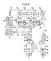
- Fig. 5 shows a second embodiment of the present invention.
- Exhaust gas tubes 651, 652, 653, 654 of four-cylinder engine 1 are gathered to two groups, and two turbo superchargers 6A and 6B are respectively driven by the groups.
- the exhaust gas system is divided into two system tubes 2A and 2B. Accordingly, exhaust gases discharged from the first and second combustion chambers 591 and 592 are, for example, fed to drive the first turbo supercharger 6A by the first and second exhaust gas tubes 651 and 652, to be then accelerated through the first exhaust gas conduit 2A by the first negative pressure generator 5A to be discharged into the atmosphere.
- the exhaust gases discharged from the third and fourth combustion chambers 593 and 594 are fed to drive the second turbo supercharger 6B by the third and fourth exhaust gas tubes 653 and 654, to be then accelerated through the second exhaust gas conduit 2B by the second negative pressure generator 5B to be discharged into the atmosphere.
- Fig. 5 further shows a modified example of the second embodiment.
- sucking means 9 is provided in the vicinity of the lowermost stream of the exhaust gas conduit 2.
- Sucking means 9A and 9B are provided immediately after catalyst units 3A and 3B.
- the other arrangement of the third embodiment is the same as that of the second embodiment, and the description thereof will be omitted with the same reference numerals designated.
- the exhaust gases exhausted from the combustion chambers may be entirely introduced into the exhaust gas turbine 61, or partly utilized, or switched between the entirety and the part.
- First and second sucking means 9A and 9B are disposed immediately after the turbine outlet 8A of a first turbo supercharger 6A or the turbine outlet 8B of a second turbo supercharger 6B, and negative pressures for driving the sucking means 9A and 9B are generated by negative pressure generators 5A and 5B. If there is a difference between the exhaust gas energy by the first and second combustion chambers 591 and 592 and the exhaust gas energy by the third and fourth combustion chambers 593 and 594 in such a manner that the former is larger than the latter, the positive pressure for driving the second turbo supercharger 6B is smaller than that of the first turbo supercharger 6A, and the negative pressure generated by the first negative pressure generator 5A becomes larger than that.
- the way of gathering the exhaust gas tubes 651 to 654 is not limited to the above example.
- they can be suitably combined such that the first and fourth combustion chambers 591 and 594, and the second and third combustion chambers 592 and 593 are respectively combined.
- they may be set by considering the sequence of ignitions of the combustion chambers.
- the air intake tube 55 communicating with the supercharging turbine 62 of the turbo supercharger is so gathered as to be connected to one air cleaner 56 and the suction tube 57 communicating with the combustion chambers from the supercharging turbine outlet is connected to one inter-cooler 58.
- they may be, of course, divided into two systems.
- the turbo supercharger 6 is positively hydraulically driven by so-called "pressing pressure of the exhaust gas flow, and simultaneously negatively hydraulically driven to be effected by suction. Therefore, since the exhaust gas itself for positively hydraulically driving the exhaust gas turbine 61 is always sucked, the exhaust gas efficiency of the exhaust gas conduit is remarkably enhanced to much higher stage. In other words, the exhaust gas turbine 61 to be driven only by the strong negative pressure formed by the negative pressure generator is simultaneously effected by the pressing of the existing exhaust gas flow.
- the exhaust gas turbine 61 is driven by both the driving forces in the pressing and the sucking directions. Therefore, in comparison with the conventional exhaust gas turbine driven only by the pressing, the rotating speed of remarkably enhanced. Since the sucking means 9 is provided in the vicinity of the discharge unit into the atmospheric air, the speed of the exhaust gas flow to be remarkably decelerated can be significantly reactivated.
- the one turbine 61 is simultaneously driven by the positive and negative pressures, its starting characteristic is improved, and its rising curve is approximated to a linear relation.
- Such simultaneous actions of both the positive and negative pressures to the turbine can enhance the supercharging pressure as compared with the conventional one even not with high accuracy and high performance of the turbine blades, and means to improve the starting characteristic.
- the drive of the exhaust gas turbine 61 reflects the rotating characteristic of the supercharging turbine 62 and the operation thereby. In other words, since the suction pressure is linearly enhanced, the charging efficiency is remarkably improved.
- the performance of the turbo supercharger is remarkably enhanced, and the suction gas temperature to be supercharged is reduced.
Landscapes
- Engineering & Computer Science (AREA)
- Chemical & Material Sciences (AREA)
- Mechanical Engineering (AREA)
- General Engineering & Computer Science (AREA)
- Combustion & Propulsion (AREA)
- Chemical Kinetics & Catalysis (AREA)
- Toxicology (AREA)
- Health & Medical Sciences (AREA)
- Physics & Mathematics (AREA)
- Fluid Mechanics (AREA)
- Supercharger (AREA)
- Exhaust Silencers (AREA)
- Exhaust Gas After Treatment (AREA)
Applications Claiming Priority (2)
| Application Number | Priority Date | Filing Date | Title |
|---|---|---|---|
| JP342769/89 | 1989-12-28 | ||
| JP1342769A JPH03202629A (ja) | 1989-12-28 | 1989-12-28 | ターボ過給機の駆動装置 |
Publications (2)
| Publication Number | Publication Date |
|---|---|
| EP0438804A1 true EP0438804A1 (fr) | 1991-07-31 |
| EP0438804B1 EP0438804B1 (fr) | 1996-09-18 |
Family
ID=18356357
Family Applications (1)
| Application Number | Title | Priority Date | Filing Date |
|---|---|---|---|
| EP90125703A Expired - Lifetime EP0438804B1 (fr) | 1989-12-28 | 1990-12-28 | Dispositif de commande de suralimentation par turbocompresseur |
Country Status (4)
| Country | Link |
|---|---|
| US (1) | US5179838A (fr) |
| EP (1) | EP0438804B1 (fr) |
| JP (1) | JPH03202629A (fr) |
| DE (1) | DE69028619T2 (fr) |
Cited By (5)
| Publication number | Priority date | Publication date | Assignee | Title |
|---|---|---|---|---|
| ES2092930A2 (es) * | 1993-04-05 | 1996-12-01 | Rosell Joan Carbo | Sistema de aprovechamiento de la energia de los gases de escape de motores termicos y utilizacion correspondiente. |
| DE19610144A1 (de) * | 1996-03-15 | 1997-09-25 | Heinrich Wirth | Dieselmotor mit oder ohne Aufladung |
| EP1012453A1 (fr) * | 1997-02-25 | 2000-06-28 | Equilibrium I Söderhamn AB | Dispositif et procede de purification de gaz d'echappement |
| EP1602810A1 (fr) * | 2004-06-04 | 2005-12-07 | ABB Turbo Systems AG | Sourdine pour compresseur |
| FR2891011A1 (fr) * | 2005-09-21 | 2007-03-23 | Melchior Jean F | Dispositif de suralimentation pour moteur a combustion interne, et vehicule automobile equipe d'un tel dispositif |
Families Citing this family (4)
| Publication number | Priority date | Publication date | Assignee | Title |
|---|---|---|---|---|
| US5400597A (en) * | 1993-06-18 | 1995-03-28 | Mirabile; Nicholas F. | Turbocharger system with electric blower |
| BRPI0620061B1 (pt) * | 2005-12-19 | 2019-09-10 | L C Eldridge Co Ltd | sistema, método e aparelho para manipular e diluir gases de exaustão de combustão interna |
| US9291079B2 (en) * | 2008-04-05 | 2016-03-22 | Mi Yan | Engine aftertreatment system with exhaust lambda control |
| CN104061062B (zh) * | 2014-06-06 | 2016-09-07 | 上海交通大学 | 带有双喷管的进排气调节系统 |
Citations (3)
| Publication number | Priority date | Publication date | Assignee | Title |
|---|---|---|---|---|
| FR2338382A1 (fr) * | 1976-01-19 | 1977-08-12 | Inst Francais Du Petrole | Dispositif perfectionne de suralimentation des moteurs a combustion interne |
| US4308718A (en) * | 1978-01-02 | 1982-01-05 | Jan Mowill | Bleedoff of gas from diffusers in fluid flow machines |
| US4864825A (en) * | 1988-01-30 | 1989-09-12 | Yoshiaki Kakuta | Suction type turbo-supercharger |
Family Cites Families (8)
| Publication number | Priority date | Publication date | Assignee | Title |
|---|---|---|---|---|
| US4548039A (en) * | 1978-09-07 | 1985-10-22 | Mtu Friedrichshafen Gmbh | Turbocharged internal combustion engine |
| JPS57135225A (en) * | 1981-02-16 | 1982-08-20 | Fuji Heavy Ind Ltd | Intake and exhaust construction for internal combustion engine |
| JPS60108723U (ja) * | 1983-12-27 | 1985-07-24 | スズキ株式会社 | 2サイクルエンジンの排気装置 |
| JPS63170541U (fr) * | 1987-04-28 | 1988-11-07 | ||
| JPH0791975B2 (ja) * | 1987-10-16 | 1995-10-09 | 義明 角田 | 内燃機関内部空気冷却機構 |
| JPH01147110A (ja) * | 1987-12-03 | 1989-06-08 | Yoshiaki Tsunoda | 吸引式空冷機構に於る負圧空気流の加速装置 |
| JPH0730705B2 (ja) * | 1987-12-21 | 1995-04-10 | 義明 角田 | 内燃機関用低速トルク発生装置 |
| JPH03107529A (ja) * | 1989-09-21 | 1991-05-07 | Yoshiaki Tsunoda | ターボ過給機の駆動方法及び駆動装置 |
-
1989
- 1989-12-28 JP JP1342769A patent/JPH03202629A/ja active Granted
-
1990
- 1990-12-26 US US07/634,336 patent/US5179838A/en not_active Expired - Fee Related
- 1990-12-28 EP EP90125703A patent/EP0438804B1/fr not_active Expired - Lifetime
- 1990-12-28 DE DE69028619T patent/DE69028619T2/de not_active Expired - Fee Related
Patent Citations (3)
| Publication number | Priority date | Publication date | Assignee | Title |
|---|---|---|---|---|
| FR2338382A1 (fr) * | 1976-01-19 | 1977-08-12 | Inst Francais Du Petrole | Dispositif perfectionne de suralimentation des moteurs a combustion interne |
| US4308718A (en) * | 1978-01-02 | 1982-01-05 | Jan Mowill | Bleedoff of gas from diffusers in fluid flow machines |
| US4864825A (en) * | 1988-01-30 | 1989-09-12 | Yoshiaki Kakuta | Suction type turbo-supercharger |
Cited By (10)
| Publication number | Priority date | Publication date | Assignee | Title |
|---|---|---|---|---|
| ES2092930A2 (es) * | 1993-04-05 | 1996-12-01 | Rosell Joan Carbo | Sistema de aprovechamiento de la energia de los gases de escape de motores termicos y utilizacion correspondiente. |
| DE19610144A1 (de) * | 1996-03-15 | 1997-09-25 | Heinrich Wirth | Dieselmotor mit oder ohne Aufladung |
| DE19610144C2 (de) * | 1996-03-15 | 1998-07-09 | Heinrich Wirth | Viertaktdieselbrennkraftmaschine, mit oder ohne Aufladung |
| EP1012453A1 (fr) * | 1997-02-25 | 2000-06-28 | Equilibrium I Söderhamn AB | Dispositif et procede de purification de gaz d'echappement |
| EP1602810A1 (fr) * | 2004-06-04 | 2005-12-07 | ABB Turbo Systems AG | Sourdine pour compresseur |
| WO2005119031A1 (fr) * | 2004-06-04 | 2005-12-15 | Abb Turbo Systems Ag | Silencieux absorbeur pour compresseurs |
| GB2429497A (en) * | 2004-06-04 | 2007-02-28 | Abb Turbo Systems Ag | Absorber silencer for compressors |
| GB2429497B (en) * | 2004-06-04 | 2008-07-23 | Abb Turbo Systems Ag | Absorber-type silencer for compressors |
| FR2891011A1 (fr) * | 2005-09-21 | 2007-03-23 | Melchior Jean F | Dispositif de suralimentation pour moteur a combustion interne, et vehicule automobile equipe d'un tel dispositif |
| EP1775441A1 (fr) * | 2005-09-21 | 2007-04-18 | Jean Frédéric Melchior | Dispositif de suralimentation pour moteur à combustion interne, et véhicule automobile équipé d'un tel dispositif |
Also Published As
| Publication number | Publication date |
|---|---|
| JPH0581733B2 (fr) | 1993-11-16 |
| DE69028619T2 (de) | 1997-02-20 |
| JPH03202629A (ja) | 1991-09-04 |
| US5179838A (en) | 1993-01-19 |
| DE69028619D1 (de) | 1996-10-24 |
| EP0438804B1 (fr) | 1996-09-18 |
Similar Documents
| Publication | Publication Date | Title |
|---|---|---|
| US3462071A (en) | Arrangements for radial flow compressors for supercharging internal combustion engines | |
| CN107002599B (zh) | 用于内燃发动机的增压装置以及用于所述增压装置的操作方法 | |
| CN107002555B (zh) | 用于内燃发动机的增压装置以及用于所述增压装置的操作方法 | |
| JPS61164039A (ja) | 多段タ−ボ過給機関 | |
| US20030136102A1 (en) | Diffuser for terrestrial or aviation gas turbine | |
| US10563572B2 (en) | Charging device for an internal combustion engine and operating method for the charging device | |
| US6651431B1 (en) | Boosted internal combustion engines and air compressors used therein | |
| GB2090913A (en) | Turbocharged ic engine with an auxiliary charge compressor | |
| US5179838A (en) | Apparatus for driving turbo supercharger | |
| JP4339643B2 (ja) | 過給式内燃機関 | |
| US4864825A (en) | Suction type turbo-supercharger | |
| CN107002551A (zh) | 用于内燃机的两级废气涡轮增压装置 | |
| GB2367096A (en) | Turbocharger arrangement with exhaust gas diverter valve | |
| GB2079380A (en) | Exhaust bypass for dual-entry exhaust turbine supercharger | |
| US5115641A (en) | Method of and apparatus for driving turbosupercharger | |
| US20070000481A1 (en) | Device for compressing combustion air | |
| EP0215754A1 (fr) | Dispositif pour la suralimentation d'un moteur à combustion interne et à plusieurs cylindres | |
| EP0323039A2 (fr) | Circuit de refroidissement par l'air d'un moteur à combustion interne | |
| EP3022431B1 (fr) | Système d'aspiration et d'éjection pour un moteur à combustion interne | |
| JPS5810117A (ja) | 排気タ−ビン過給機 | |
| KR100271467B1 (ko) | 배기터빈과급기엔진의저속보상장치 | |
| EP0445805B1 (fr) | Dispositif d'entraînement d'un turbocompresseur | |
| GB2118621A (en) | Two stage i.c. engine supercharging | |
| JP2523320B2 (ja) | タ−ボエンジンの排気システム | |
| CN110578627A (zh) | 具有压缩机的增压内燃发动机以及用于操作所述类型的内燃发动机的方法 |
Legal Events
| Date | Code | Title | Description |
|---|---|---|---|
| PUAI | Public reference made under article 153(3) epc to a published international application that has entered the european phase |
Free format text: ORIGINAL CODE: 0009012 |
|
| 17P | Request for examination filed |
Effective date: 19901228 |
|
| AK | Designated contracting states |
Kind code of ref document: A1 Designated state(s): DE FR GB IT |
|
| 17Q | First examination report despatched |
Effective date: 19930202 |
|
| GRAH | Despatch of communication of intention to grant a patent |
Free format text: ORIGINAL CODE: EPIDOS IGRA |
|
| GRAA | (expected) grant |
Free format text: ORIGINAL CODE: 0009210 |
|
| GRAH | Despatch of communication of intention to grant a patent |
Free format text: ORIGINAL CODE: EPIDOS IGRA |
|
| AK | Designated contracting states |
Kind code of ref document: B1 Designated state(s): DE FR GB IT |
|
| REF | Corresponds to: |
Ref document number: 69028619 Country of ref document: DE Date of ref document: 19961024 |
|
| ITF | It: translation for a ep patent filed | ||
| ET | Fr: translation filed | ||
| PLBE | No opposition filed within time limit |
Free format text: ORIGINAL CODE: 0009261 |
|
| STAA | Information on the status of an ep patent application or granted ep patent |
Free format text: STATUS: NO OPPOSITION FILED WITHIN TIME LIMIT |
|
| 26N | No opposition filed | ||
| PGFP | Annual fee paid to national office [announced via postgrant information from national office to epo] |
Ref country code: GB Payment date: 19971212 Year of fee payment: 8 |
|
| PGFP | Annual fee paid to national office [announced via postgrant information from national office to epo] |
Ref country code: FR Payment date: 19971230 Year of fee payment: 8 |
|
| PGFP | Annual fee paid to national office [announced via postgrant information from national office to epo] |
Ref country code: DE Payment date: 19980123 Year of fee payment: 8 |
|
| PG25 | Lapsed in a contracting state [announced via postgrant information from national office to epo] |
Ref country code: GB Free format text: LAPSE BECAUSE OF NON-PAYMENT OF DUE FEES Effective date: 19981228 |
|
| GBPC | Gb: european patent ceased through non-payment of renewal fee |
Effective date: 19981228 |
|
| PG25 | Lapsed in a contracting state [announced via postgrant information from national office to epo] |
Ref country code: FR Free format text: LAPSE BECAUSE OF NON-PAYMENT OF DUE FEES Effective date: 19990831 |
|
| REG | Reference to a national code |
Ref country code: FR Ref legal event code: ST |
|
| PG25 | Lapsed in a contracting state [announced via postgrant information from national office to epo] |
Ref country code: DE Free format text: LAPSE BECAUSE OF NON-PAYMENT OF DUE FEES Effective date: 19991001 |
|
| PG25 | Lapsed in a contracting state [announced via postgrant information from national office to epo] |
Ref country code: IT Free format text: LAPSE BECAUSE OF NON-PAYMENT OF DUE FEES;WARNING: LAPSES OF ITALIAN PATENTS WITH EFFECTIVE DATE BEFORE 2007 MAY HAVE OCCURRED AT ANY TIME BEFORE 2007. THE CORRECT EFFECTIVE DATE MAY BE DIFFERENT FROM THE ONE RECORDED. Effective date: 20051228 |