EP0438876A1 - Fabrication de fibres optiques dopées - Google Patents
Fabrication de fibres optiques dopées Download PDFInfo
- Publication number
- EP0438876A1 EP0438876A1 EP90313204A EP90313204A EP0438876A1 EP 0438876 A1 EP0438876 A1 EP 0438876A1 EP 90313204 A EP90313204 A EP 90313204A EP 90313204 A EP90313204 A EP 90313204A EP 0438876 A1 EP0438876 A1 EP 0438876A1
- Authority
- EP
- European Patent Office
- Prior art keywords
- filament
- core section
- core
- cladding
- preform
- Prior art date
- Legal status (The legal status is an assumption and is not a legal conclusion. Google has not performed a legal analysis and makes no representation as to the accuracy of the status listed.)
- Granted
Links
Images


Classifications
-
- C—CHEMISTRY; METALLURGY
- C03—GLASS; MINERAL OR SLAG WOOL
- C03C—CHEMICAL COMPOSITION OF GLASSES, GLAZES OR VITREOUS ENAMELS; SURFACE TREATMENT OF GLASS; SURFACE TREATMENT OF FIBRES OR FILAMENTS MADE FROM GLASS, MINERALS OR SLAGS; JOINING GLASS TO GLASS OR OTHER MATERIALS
- C03C13/00—Fibre or filament compositions
- C03C13/04—Fibre optics, e.g. core and clad fibre compositions
- C03C13/045—Silica-containing oxide glass compositions
-
- C—CHEMISTRY; METALLURGY
- C03—GLASS; MINERAL OR SLAG WOOL
- C03B—MANUFACTURE, SHAPING, OR SUPPLEMENTARY PROCESSES
- C03B37/00—Manufacture or treatment of flakes, fibres, or filaments from softened glass, minerals, or slags
- C03B37/01—Manufacture of glass fibres or filaments
- C03B37/012—Manufacture of preforms for drawing fibres or filaments
- C03B37/01205—Manufacture of preforms for drawing fibres or filaments starting from tubes, rods, fibres or filaments
- C03B37/01211—Manufacture of preforms for drawing fibres or filaments starting from tubes, rods, fibres or filaments by inserting one or more rods or tubes into a tube
-
- C—CHEMISTRY; METALLURGY
- C03—GLASS; MINERAL OR SLAG WOOL
- C03B—MANUFACTURE, SHAPING, OR SUPPLEMENTARY PROCESSES
- C03B2201/00—Type of glass produced
- C03B2201/02—Pure silica glass, e.g. pure fused quartz
- C03B2201/03—Impurity concentration specified
- C03B2201/04—Hydroxyl ion (OH)
-
- C—CHEMISTRY; METALLURGY
- C03—GLASS; MINERAL OR SLAG WOOL
- C03B—MANUFACTURE, SHAPING, OR SUPPLEMENTARY PROCESSES
- C03B2201/00—Type of glass produced
- C03B2201/06—Doped silica-based glasses
- C03B2201/30—Doped silica-based glasses doped with metals, e.g. Ga, Sn, Sb, Pb or Bi
- C03B2201/34—Doped silica-based glasses doped with metals, e.g. Ga, Sn, Sb, Pb or Bi doped with rare earth metals, i.e. with Sc, Y or lanthanides, e.g. for laser-amplifiers
- C03B2201/36—Doped silica-based glasses doped with metals, e.g. Ga, Sn, Sb, Pb or Bi doped with rare earth metals, i.e. with Sc, Y or lanthanides, e.g. for laser-amplifiers doped with rare earth metals and aluminium, e.g. Er-Al co-doped
-
- C—CHEMISTRY; METALLURGY
- C03—GLASS; MINERAL OR SLAG WOOL
- C03B—MANUFACTURE, SHAPING, OR SUPPLEMENTARY PROCESSES
- C03B2203/00—Fibre product details, e.g. structure, shape
- C03B2203/10—Internal structure or shape details
- C03B2203/22—Radial profile of refractive index, composition or softening point
-
- Y—GENERAL TAGGING OF NEW TECHNOLOGICAL DEVELOPMENTS; GENERAL TAGGING OF CROSS-SECTIONAL TECHNOLOGIES SPANNING OVER SEVERAL SECTIONS OF THE IPC; TECHNICAL SUBJECTS COVERED BY FORMER USPC CROSS-REFERENCE ART COLLECTIONS [XRACs] AND DIGESTS
- Y10—TECHNICAL SUBJECTS COVERED BY FORMER USPC
- Y10S—TECHNICAL SUBJECTS COVERED BY FORMER USPC CROSS-REFERENCE ART COLLECTIONS [XRACs] AND DIGESTS
- Y10S65/00—Glass manufacturing
- Y10S65/90—Drying, dehydration, minimizing oh groups
Definitions
- This invention relates to fabrication of optical fiber preforms and the resulting optical fibers and, more particularly, to fabrication techniques wherein the preforms and resulting fibers include dopant material such as rare-earth dopants.
- Optical amplifiers in intermediate optical repeaters, low noise pre-amplifiers in receivers, and high power post-amplifiers in transmitters are important elements in most lightwave communication and transmission systems of interest.
- a potentially valuable embodiment of such amplifiers is the fiber amplifier which permits amplification by incorporation of dopant material such as rare earth ions in a host fiber.
- erbium is the dopant material of choice for silica-based fibers because both the pump and signal wavelengths are supported in the host fiber with relatively low intrinsic loss.
- Delivery of rare earth species to the reaction and deposition zone during fiber preform fabrication have been devised for standard techniques such as modified chemical vapor deposition (MCVD), vapor axial deposition (VAD), and outside vapor deposition (OVD). These delivery methods require a high degree of accuracy and temperature control of the vapors to insure commencement of the necessary chemical reactions for incorporation of the rare earth ions.
- Solution doping techniques have also been proposed for incorporating low volatility rare earth ions delivered as halides into high purity fiber preforms formed by each of the techniques listed above. This doping technique also requires a certain amount of control owing to the low vapor pressure of the rare earth dopants.
- Reproducible doped optical fiber preforms having a predetermined dopant concentration level are fabricated by inserting a doped filament into a substantially completed preform so that the filament will be centrally located in the core region upon collapse or consolidation of the preform. Since the dopant concentration level of the doped filament is known prior to its insertion in the preform, the dopant concentration level is controllable and calibrated to achieve the desired concentration in the resulting fiber. Dopant materials such as rare earth elements and other elements are suitable for use by this technique.
- Optical fiber amplifiers are generally embodied as a standard optical fiber having core and cladding regions and dopant material substantially contained in the core region for providing gain via stimulated emission.
- Popular dopant materials for achieving stimulated emission in fiber amplifiers are found in the rare earth or lanthanide ions such as Nd3+, Ho3+, Eu3+, Er3+, Yb3+, Th3+, and Dy3+.
- the elements such as Nd3+ and Er3+ are commonly used because of the compatibility of the pump wavelength for these materials with the loss minima in the silica-based fibers.
- the embodiments employ Er3+ ions for achieving signal amplification in silica-based fibers.
- the description of the particular fiber and the particular dopant material is intended to be for illustrative purposes and is not intended for purposes of limitation.
- fiber structures can be employed for fiber amplifiers. That is, structures known to those skilled in the art may be employed such as depressed cladding fibers, dispersion shifted fibers, quadruple clad fibers, polarization maintaining fibers, step-index core fibers and the like. All these fiber structures are capable of being manufactured by standard techniques such as vapor axial deposition (VAD), outside vapor deposition (OVD), and modified chemical vapor deposition (MCVD). It is contemplated that any and all the fiber structures may be employed in accordance with the principles of the invention for preform and fiber fabrication.
- VAD vapor axial deposition
- OLED outside vapor deposition
- MCVD modified chemical vapor deposition
- the process of fabricating a doped optical fiber preform and, ultimately, a doped optical fiber includes depositing cladding and core regions for the preform according to a standard deposition technique such as MCVD, VAD, OVD or the like, inserting a filament having a calibrated amount of dopant ions such as Er3+ or the like into a region so that it is surrounded by the core, consolidating or collapsing the cladding and core around the doped filament to form the doped preform structure with the core section engaging the filament, and drawing the doped optical fiber from the doped preform using standard fiber drawing techniques.
- the filament is formed by standard fiber fabrication and doping techniques.
- MCVD fabrication of a standard silica-based preform including solution doping with rare earth ions and subsequent diving and collapse was followed by a fiber drawing step to realize a doped filament having a pre-calibrated dopant concentration.
- the filament is a "seed fiber". This term is used to connote the operation of the filament seeding the preform structure with dopant material. However, to avoid confusion, the term filament is being used to distinguish it from the doped optical fiber drawn from the doped optical fiber preform which incorporated the filament.
- modified chemical vapor deposition as an exemplary standard deposition method and solution doping as an exemplary method for introducing dopant materials into a preform. Both of these techniques are employed to form an exemplary filament. That is, the exemplary doped preform is fabricated using MCVD processing together with vapor phase doping followed by standard fiber drawing methods to form the doped filament. After the doped filament has been drawn, its dopant concentration is measured and the filament is prepared for insertion into the cylindrical opening formed in the core region of the deposited materials comprising the preform.
- MCVD is the simplest and perhaps most flexible of the lightguide processes. It starts with a tube, typically commercial silica, which provides part of the cladding in the lightguide structure, and also acts as a containment vessel for the deposition process.
- the tube is characterized and selected for dimensions, siding, cross-sectional area and uniformity, and cleaned prior to use.
- the deposition station consists of a glass working lathe, a chemical delivery system, and associated computer control console.
- the entrance end of the tube is mounted in one of two synchronously rotating chucks of the lathe and coupled to the chemical delivery system via a rotating joint.
- the other end of the tube is flared and fused to a larger tube mounted in the second chuck; this large tube serves to collect unincorporated material resulting from the deposition process and is coupled to a chemical scrubbing system. After setup of the tube, it is rotated and fire polished by means of a traversing heat source. Next, the deposition phase of the process begins.
- the basic deposition process predominantly involves the high temperature homogeneous gas phase oxidation of volatile vapor delivered compounds that are deposited as submicron particles via thermophoresis and fused to a clear glass film.
- the deposition process uses controlled amounts of chemical reagents entrained in a gas stream by passing carrier gases such as O2 or He through liquid dopant sources such as SiCl4, GeCl4, or POCl3 or direct proportionation of gaseous dopants such as SiF4, BCl3, and CCl2.
- carrier gases such as O2 or He
- liquid dopant sources such as SiCl4, GeCl4, or POCl3 or direct proportionation of gaseous dopants such as SiF4, BCl3, and CCl2.
- this method of delivery acts as a purification step relative to transition metal impurities which might be contained in raw materials, and are characterized by much lower vapor pressures.
- the chemical gas mixture is injected into the rotating tube where a hot zone is traversed along the length of the tube by an
- the temperature of the hot zone is controlled via optical pyrometry monitoring and feedback to a flame temperature controller.
- Layer by layer of material is deposited and sufficient heat from the moving heat source results in the sintering of the deposit as the hot zone passes over it.
- first high purity cladding is deposited, then core.
- This cladding serves a number of functions: it acts as a barrier to in-diffusion of impurities, particularly OH, into the active region of the lightguide; it insures low cladding losses for any power which propagates in the cladding; lastly, it minimizes any scattering losses that might occur due to tubing defects or interfacial irregularities at the tubing inner surface.
- the deposited cladding can also serve the additional function of allowing more complex, dispersion optimized designs to be made, by tailoring the cladding index profile. Core deposition ensues next, involving 30-70 layers for multimode structures, versus one to several layers for single-mode structures.
- the deposited cladding can be a variety of index matched or depressed compositions in the F-SiO2-GeO2-P2O5 system, where small amounts of P2O5 are sometimes used predominantly to decrease the deposition temperature.
- Core compositions are typically GeO2-SiO2, where small amounts of P2O5 are used for graded index multimode fibers.
- the dimensions and refractive index profile of the eventual fiber structure is built up by depositing successive layers of controlled composition to the desired thickness, then collapsing the composite tube plus deposit to a solid preform rod. The total number of deposited layers is chosen on the basis of starting tube dimensions, deposition rate, profile complexity and fiber design.
- FIG. 1 depicts a lathe 1 holding substrate tube 2 within which a hot zone 3 is produced by heating means 4.
- Tube 2 may be rotated, for example, in the direction shown by arrow 5a by means not shown and hot zone 3 is caused to traverse tube 2 by movement of heating means 4 as schematically depicted by double headed arrow 5b, for example, by a threaded feed member 6.
- a gaseous material is introduced into tube 2 via inlet tube 7 which is, in turn, connected to source material reservoirs 8.
- source material reservoirs may include an oxygen inlet 9 connected to means not shown.
- gaseous material may also be introduced by inlets 10 and 11 by means not shown and through inlet 12 from reservoir 13.
- Reservoirs 14 and 15 contain normally liquid reactant material which is introduced into tube 2 by means of carrier gas introduced through inlets 10 and 11 with the arrangement being such that the carrier gas is bubbled through such liquids 16 and 17. Exiting material is exhausted through outlet 18. Not shown is the arrangement of mixing valves and shut off valves which may be utilized to meter flows and to make other necessary adjustments in composition.
- the apparatus of FIG. 1 is generally horizontally disposed.
- the apparatus of FIG. 1 can be disposed vertically with only minor modifications while maintaining its operational characteristic quite similar to the apparatus of FIG. 1.
- Vertical disposition of the substrate tube lends stability to the portion of the tube within the hot zone and may permit attainment of higher temperature or of longer hot zones in the traversal direction without objectionable distortion.
- FIG. 2 is a front elevational view of a section of a substrate tube 30 as observed during deposition. Depicted is a heating means 31 producing a hot zone 32 which is traversing tube 30 in the direction shown by arrow 33 by means not shown. Gaseous material is introduced at the left end of tube 30 and flows in the broken section of the figure in the direction shown by arrow 34. For the processing condition, two regions are clearly observable. Zone 35 downstream of hot zone 32 is filled with a moving powdery suspension of particular oxidic material, while region 36, devoid of such particulate matter, defines the region within which fusion of deposited material is occurring.
- Tube 30 is heated to a high temperature by moving the oxyhydrogen torch 31 slowly along the length of the tube. As the torch traverses the tube, the temperature of the glass reaches its softening point. When the softening point is reached, the surface tension causes the tube with it's deposited glass layers to collapse uniformly into a solid rod called a preform.
- the final step in the optical fiber fabrication process is drawing the fiber from the preform.
- Fiber drawing is accomplished by inserting the preform structure into a high temperature furnace by means of a preform feed mechanism. Alignment and centering of the preform relative to the furnace is critical. This can be accomplished by manual or automated alignment techniques well known to those skilled in the art.
- For silica fiber drawing considerations with respect to glass viscosity require draw temperatures in the range of 1900 to 2300°C.
- the tip of the preform softens as it is fed into the high temperature furnace. Both gravity and an applied tensile force causes the glass to "neck down" to a small diameter fiber.
- the shape of the neck down region is determined by a variety of factors including the thermal gradient in the furnace and applied draw forces.
- a control tensile force is sustained by using a fiber pulling capstan or some other source of tension.
- the preform feed rate and capstan rotation rate determine the draw-down ratio from preform to fiber.
- preforms ranging from 10 to 70mm are drawn down to fiber in the 100 to 225 ⁇ m range.
- Fiber diameter control is most commonly achieved by varying the draw speed while feeding preforms at a fixed rate through a constant temperature heat source.
- In-line processes are known to those skilled in the art for applying protective coatings to the glass fiber as it is being drawn.
- the doped filament is fabricated by standard optical fiber fabrication processes which include a standard process for introduction of dopant material for its incorporation in the preform which is ultimately drawn to form the filament.
- Methods have been devised for a dopant delivery to the reaction and deposition zones during preform fabrication using MCVD and VAD or OVD techniques. These methods comprise both vapor phase delivery and liquid phase delivery methods.
- heated sponge, heated source and heated source injector deliver dopant materials such as rare earth chloride vapor for reaction downstream by oxidation along with other standard reactors.
- the low pressure reactant is accommodated by bringing the vapor source close to the reaction zone and immediately diluting the source by mixing with other reactants.
- the heated sponge source is made by soaking a porous soot region deposited on the upstream inner wall of an MCVD tube using a rare earth chloride solution. Upon heating and after dehydration, the sponge becomes a source for rare earth dopants. Both other methods use heated chloride directly as a source after dehydration.
- An additional vapor phase dopant delivery method in MCVD processing is the aerosol delivery method. This method overcomes the need for heated source compounds in that the vapor is generated at the reaction site. While aerosol delivery provides a means for incorporating a variety of dopants, it requires consideration for the reaction or elimination of carrier liquid products such as OH.
- Liquid phase methods have also been devised for use in MCVD processing. These methods include soot impregnation, molecular stuffing and solution doping.
- an unsintered or porous layer of silica is first deposited inside the tube by the MCVD process. Doping occurs by filling the tube with an aqueous solution of a rare earth chloride. The solution is allowed to soak into the unsintered layer for approximately one hour prior to draining. The impregnated layer is then dried at high temperatures in the presence of a flowing mixture of Cl2 and O2.
- the solution doping method is described in more detail in Electronics Letters, Vol. 23, No. 7, pages 329-331 (1987). This article is expressly incorporated herein by reference.
- Fabrication of the doped optical fiber preform is illustrated in the sequence of Figures beginning at FIG. 3 and continuing through FIG. 5.
- substrate tube 40 is shown in cross-section undergoing MCVD processing similar to that shown in FIGS. 1 and 2.
- the region designated as region 41 includes cladding and core sections in sequence from outermost to innermost.
- the combination, composition, and index profile of the cladding and core sections determines the type of doped fiber to be fabricated
- Oxyhydrogen torch 31 heats the substrate 2 by traversing the tube along the direction shown as arrow 44.
- Accumulating soot 42 and undeposited region 43 are shown for completeness of understanding.
- a substantially cylindrical opening 47 has been caused to be formed substantially in the center and along the longitudinal axis of the core section. It may be desirable at this point to begin consolidating and collapsing the deposited materials in tube 40 by applying heat from torch 31 along the length of the tube, thereby softening and collapsing the glass materials. If undertaken initially, collapsing should proceed up to such a point where there is sufficient clearance for insertion of the doped filament 45. While the cylindrical opening generally maintains a substantially cylindrical shape after initial collapse, it is contemplated that known vacuum techniques can be applied to cause the opening to deviate to a substantially elliptical shape.
- the doped filament is generally fabricated to have an outside diameter of approximately several hundred microns. It is contemplated that the filament have an outside diameter less than or equal to 500 ⁇ m.
- the doped filament 45 is inserted into the opening formed in the core section either before any initial collapse or after an initial collapse. Insertion commences by pushing the filament into the core opening from the dust collector end of the MCVD reactor. It is expected that the opening has an approximate diameter on the order of 1 mm.
- heat is generally applied by oxyhydrogen torch 31 to the entire substrate tube prior to insertion and/or during insertion. Further, consideration should be given to elimination of contaminants such as OH.
- a moving stream of gas mixture including at least one from the group consisting of O2 and Cl2 is provided into the cylindrical opening from the end opposite that which insertion is commenced, that is, opposite the dust collector end. As shown in FIG. 4, insertion occurs from right to left. Hence, the moving stream of gases would be introduced in the opposite direction, that is, from left to right.
- a doped optical fiber preform is fabricated. This preform can be drawn using standard techniques to obtain the doped optical fiber.
- Doped optical fibers drawn from doped preforms fabricated in accordance with the principles of the invention have the unique properties that highly volatile dopant materials are concentrated substantially along the center axis of the core section of the fiber and the dopant materials are introduced in an amount calibrated to provide a desired concentration in the fiber without requiring chemical reaction between the dopant materials and the deposited core materials. Centering the dopant material in the core is preferred because such a dopant location optimizes pump efficiency. Calibration of the dopant concentration in the filament and ultimately, by scaling, in the doped fiber is accomplished by measuring the loss in the filament prior to insertion to insure predictable and uniform end-to-end dopant concentration in the fiber.
- the filament was fabricated by MCVD using a low OH (5 ppm OH by wt.) F300 Amersil support tube having dimensions 19mm x 25mm, inner diameter and outer diameter, respectively.
- An erbium doped aluminosilicate core was deposited in the support tube using vapor phase dopant delivery to yield a numerical aperture of 0.15 with a mole percent alumina composition of approximately 3.3.
- a refractive index profile for the core section relative to the support tube (zero baseline) is shown in FIG. 6. After consolidation and collapse of this doped structure to form a preform, the doped filament was drawn using standard techniques known to those skilled in the art.
- Filaments having two different dimensions were drawn, namely, a filament having a 32 ⁇ m core diameter and a 150 ⁇ m outer diameter and a filament having a 7.4 ⁇ m core diameter and a 100 ⁇ m outer diameter.
- the spectral loss for such a filament is shown in Fig. 7 wherein a peak absorption of 38dB/m occurs at 1.53 ⁇ m which indicates an erbium oxide concentration of approximately 1400ppm.
- the doped optical fiber preform and the resulting doped optical fiber were fabricated by an MCVD process.
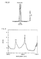
- a fluorine phosphorus doped cladding layer was first deposited in a standard TO8 Amersil 19X25 support tube. Following deposition of the cladding, a germanium silicate core was deposited. The support tube was collapsed so that, after insertion of the filament, only one additional traverse of the torch was necessary to complete fabrication of the preform structure.
- a refractive index profile for the second exemplary preform is shown in FIG. 8.
- a corresponding loss or absorption spectrum for the fiber drawn from this preform is shown in FIG. 9. The two large loss peaks shown in FIG. 9 relate to OH and Er3+ absorption.
- the doped fiber characterized by FIGs. 8 and 9 was drawn to a length of 9.5 km.
- the doped fiber exhibited sufficient loss compensation to achieve transparency.
- the filament may be a doped dispersion shifted fiber structure, a doped polarization maintaining fiber structure or the like.
- filaments having protective jackets may also be used. It is expected that insertion of such filaments in an atmosphere of O2 will cause pyrolization of the jacket leaving no appreciable residue behind.
- a rigid member may be bonded or attached to an end of the filament so that it can be inserted in the opening and be used to pull the filament through the core.
- the present process of forming a doped preform does not require chemical reaction of the dopant material with the deposited core material. In effect, the dopant materials are locked into the filament and are thereby stabilized. As opposed to standard rod and tube techniques, the present process does not require volatilization of the dopant materials.
- the present process permits incorporation of common dopant materials as well as dopant material which could not otherwise be deposited by standard vapor phase delivery or liquid phase delivery techniques.
Landscapes
- Chemical & Material Sciences (AREA)
- Engineering & Computer Science (AREA)
- Organic Chemistry (AREA)
- Life Sciences & Earth Sciences (AREA)
- Geochemistry & Mineralogy (AREA)
- Materials Engineering (AREA)
- Optics & Photonics (AREA)
- Chemical Kinetics & Catalysis (AREA)
- General Chemical & Material Sciences (AREA)
- Physics & Mathematics (AREA)
- General Life Sciences & Earth Sciences (AREA)
- Manufacturing & Machinery (AREA)
- Manufacture, Treatment Of Glass Fibers (AREA)
Applications Claiming Priority (2)
| Application Number | Priority Date | Filing Date | Title |
|---|---|---|---|
| US468433 | 1990-01-22 | ||
| US07/468,433 US5059230A (en) | 1990-01-22 | 1990-01-22 | Fabrication of doped filament optical fibers |
Publications (2)
| Publication Number | Publication Date |
|---|---|
| EP0438876A1 true EP0438876A1 (fr) | 1991-07-31 |
| EP0438876B1 EP0438876B1 (fr) | 1995-08-16 |
Family
ID=23859794
Family Applications (1)
| Application Number | Title | Priority Date | Filing Date |
|---|---|---|---|
| EP90313204A Expired - Lifetime EP0438876B1 (fr) | 1990-01-22 | 1990-12-05 | Fabrication de fibres optiques dopées |
Country Status (4)
| Country | Link |
|---|---|
| US (1) | US5059230A (fr) |
| EP (1) | EP0438876B1 (fr) |
| JP (1) | JP2527849B2 (fr) |
| DE (1) | DE69021709T2 (fr) |
Cited By (4)
| Publication number | Priority date | Publication date | Assignee | Title |
|---|---|---|---|---|
| EP0501429A1 (fr) * | 1991-02-25 | 1992-09-02 | Sumitomo Electric Industries, Ltd | Procédé pour la fabrication d'une préforme de verre pour des fibres optiques |
| EP0972752A1 (fr) * | 1998-07-14 | 2000-01-19 | Lucent Technologies Inc. | Grande préforme pour une fibre monomode et procédé pour sa fabrication |
| WO2002090277A1 (fr) * | 2001-05-04 | 2002-11-14 | Blazephotonics Limited | Procede et appareil relatif aux fibres optiques |
| WO2007035131A3 (fr) * | 2005-09-22 | 2007-10-04 | Nauchny Ts Volokonnoi Optiki P | Fibre optique amplificatrice fonctionnant sur une longueur d'onde comprise entre 1000 et 1700 nm, procedes de fabrication de la fibre optique, et laser a fibre |
Families Citing this family (11)
| Publication number | Priority date | Publication date | Assignee | Title |
|---|---|---|---|---|
| US6109065A (en) * | 1998-04-22 | 2000-08-29 | Lucent Technologies, Inc. | Method of making optical waveguide devices using perchloryl fluoride to make soot |
| US20020186942A1 (en) * | 2001-05-01 | 2002-12-12 | Bubnov Mikhail M. | Low-loss highly phosphorus-doped fibers for Raman amplification |
| US6574994B2 (en) | 2001-06-18 | 2003-06-10 | Corning Incorporated | Method of manufacturing multi-segmented optical fiber and preform |
| US6909538B2 (en) | 2002-03-08 | 2005-06-21 | Lightwave Electronics | Fiber amplifiers with depressed cladding and their uses in Er-doped fiber amplifiers for the S-band |
| EP1488548A4 (fr) * | 2002-03-08 | 2009-11-11 | Lightwave Electronics | Systeme de communication et appareil d'amplification a bande divisee mettant en oeuvre un amplificateur a fibre a profil deprime |
| FI115134B (fi) * | 2002-06-28 | 2005-03-15 | Liekki Oy | Menetelmä seostetun lasimateriaalin valmistamiseksi |
| US7848606B1 (en) * | 2008-03-13 | 2010-12-07 | The United States Of America As Represented By The Administrator Of The National Aeronautics And Space Administration | Eliminating crystals in non-oxide optical fiber preforms and optical fibers |
| US9164230B2 (en) * | 2013-03-15 | 2015-10-20 | Ofs Fitel, Llc | High-power double-cladding-pumped (DC) erbium-doped fiber amplifier (EDFA) |
| US9207397B2 (en) | 2013-11-14 | 2015-12-08 | Corning Incorporated | Light diffusing fiber with low melting temperature glass |
| CN116854360A (zh) * | 2023-07-20 | 2023-10-10 | 江苏亨通光纤科技有限公司 | 一种稀土掺杂光纤预制棒芯棒、制备方法及光纤 |
| CN117185644B (zh) * | 2023-09-01 | 2025-10-28 | 长飞光纤光缆股份有限公司 | 掺镱光纤预制棒、掺镱有源光纤及其制备方法 |
Citations (2)
| Publication number | Priority date | Publication date | Assignee | Title |
|---|---|---|---|---|
| US4737179A (en) * | 1985-08-14 | 1988-04-12 | Sumitomo Electric Industries, Ltd. | Method for producing glass preform for optical fiber |
| EP0326037A2 (fr) * | 1988-01-21 | 1989-08-02 | Polaroid Corporation | Procédé d'évaporisation sélective pour préparer des fibres optiques |
Family Cites Families (9)
| Publication number | Priority date | Publication date | Assignee | Title |
|---|---|---|---|---|
| GB1434977A (en) * | 1972-10-13 | 1976-05-12 | Sumitomo Electroc Ind Ltd | Method of manufacturing an optical waveguide |
| US4217027A (en) * | 1974-02-22 | 1980-08-12 | Bell Telephone Laboratories, Incorporated | Optical fiber fabrication and resulting product |
| US3966446A (en) * | 1975-10-23 | 1976-06-29 | Bell Telephone Laboratories, Incorporated | Axial fabrication of optical fibers |
| US4230396A (en) * | 1978-07-31 | 1980-10-28 | Corning Glass Works | High bandwidth optical waveguides and method of fabrication |
| JPS5792536A (en) * | 1980-11-29 | 1982-06-09 | Dainichi Nippon Cables Ltd | Preparation of parent material of optical glass fiber |
| US4616901A (en) * | 1982-04-09 | 1986-10-14 | At&T Bell Laboratories | Doped optical fiber |
| WO1987001110A1 (fr) * | 1985-08-13 | 1987-02-26 | Simon Blanchette Poole | Fabrication de fibres optiques |
| US4820322A (en) * | 1986-04-28 | 1989-04-11 | American Telephone And Telegraph Company At&T Bell Laboratories | Method of and apparatus for overcladding a glass rod |
| KR900003449B1 (ko) * | 1986-06-11 | 1990-05-19 | 스미도모덴기고오교오 가부시기가이샤 | 분산 시프트싱글모우드 광파이버 및 그 제조방법 |
-
1990
- 1990-01-22 US US07/468,433 patent/US5059230A/en not_active Expired - Fee Related
- 1990-12-05 EP EP90313204A patent/EP0438876B1/fr not_active Expired - Lifetime
- 1990-12-05 DE DE69021709T patent/DE69021709T2/de not_active Expired - Fee Related
-
1991
- 1991-01-22 JP JP3020425A patent/JP2527849B2/ja not_active Expired - Fee Related
Patent Citations (2)
| Publication number | Priority date | Publication date | Assignee | Title |
|---|---|---|---|---|
| US4737179A (en) * | 1985-08-14 | 1988-04-12 | Sumitomo Electric Industries, Ltd. | Method for producing glass preform for optical fiber |
| EP0326037A2 (fr) * | 1988-01-21 | 1989-08-02 | Polaroid Corporation | Procédé d'évaporisation sélective pour préparer des fibres optiques |
Cited By (7)
| Publication number | Priority date | Publication date | Assignee | Title |
|---|---|---|---|---|
| EP0501429A1 (fr) * | 1991-02-25 | 1992-09-02 | Sumitomo Electric Industries, Ltd | Procédé pour la fabrication d'une préforme de verre pour des fibres optiques |
| EP0972752A1 (fr) * | 1998-07-14 | 2000-01-19 | Lucent Technologies Inc. | Grande préforme pour une fibre monomode et procédé pour sa fabrication |
| US6105396A (en) * | 1998-07-14 | 2000-08-22 | Lucent Technologies Inc. | Method of making a large MCVD single mode fiber preform by varying internal pressure to control preform straightness |
| WO2002090277A1 (fr) * | 2001-05-04 | 2002-11-14 | Blazephotonics Limited | Procede et appareil relatif aux fibres optiques |
| US7106932B2 (en) | 2001-05-04 | 2006-09-12 | Crystal Fibre A/S | Method and apparatus relating to optical fibers |
| WO2007035131A3 (fr) * | 2005-09-22 | 2007-10-04 | Nauchny Ts Volokonnoi Optiki P | Fibre optique amplificatrice fonctionnant sur une longueur d'onde comprise entre 1000 et 1700 nm, procedes de fabrication de la fibre optique, et laser a fibre |
| US8509588B2 (en) | 2005-09-22 | 2013-08-13 | Fiber Optics Research Center Of The Russian Academy Of Sciences | Amplifying optical fiber operating at a wavelength in the range of 1000-1700 nm, methods of fabricating the same, and fiber laser |
Also Published As
| Publication number | Publication date |
|---|---|
| JP2527849B2 (ja) | 1996-08-28 |
| DE69021709T2 (de) | 1996-04-18 |
| US5059230A (en) | 1991-10-22 |
| EP0438876B1 (fr) | 1995-08-16 |
| JPH04317431A (ja) | 1992-11-09 |
| DE69021709D1 (de) | 1995-09-21 |
Similar Documents
| Publication | Publication Date | Title |
|---|---|---|
| EP0139348B1 (fr) | Fibre optique et procédé de sa fabrication | |
| CA1145172A (fr) | Guide de lumiere a grande longueur d'onde a faibles pertes | |
| US6192713B1 (en) | Apparatus for the manufacture of glass preforms | |
| EP0438876B1 (fr) | Fabrication de fibres optiques dopées | |
| EP0547335B1 (fr) | Procédé de fabrication de tubes en verre de silice dopé par le bore et le fluor | |
| US4810276A (en) | Forming optical fiber having abrupt index change | |
| CA1123684A (fr) | Methode de fabrication de guides de lumiere secs | |
| EP0556580B1 (fr) | Procédé de dopage de préformes de verre poreux | |
| EP1098857A1 (fr) | Procede et dispositif de production d'une preforme de fibre optique dopee avec une terre rare | |
| EP2655274B1 (fr) | Procédé de fabrication d'une préforme en verre pour fibre optique | |
| US4335934A (en) | Single mode fibre and method of making | |
| US4504297A (en) | Optical fiber preform manufacturing method | |
| EP0177040B1 (fr) | Procédé de fabrication d'une préforme en verre pour fibres optiques | |
| EP0105327A4 (fr) | Reduction de la conicite d'une preforme de fibre optique. | |
| US4318726A (en) | Process for producing optical fiber preform | |
| US6834516B2 (en) | Manufacture of optical fiber preforms using modified VAD | |
| EP0055822A1 (fr) | Ligne de transmission optique et son procédé de fabrication | |
| EP0251312B1 (fr) | Procédé pour la fabrication d'une préforme pour les fibres monomodes | |
| US20070137256A1 (en) | Methods for optical fiber manufacture | |
| EP0185975A1 (fr) | Procédé de fabrication d'une préforme en verre | |
| AU698054B2 (en) | Increasing the retention of GeO2 during production of glass articles |
Legal Events
| Date | Code | Title | Description |
|---|---|---|---|
| PUAI | Public reference made under article 153(3) epc to a published international application that has entered the european phase |
Free format text: ORIGINAL CODE: 0009012 |
|
| AK | Designated contracting states |
Kind code of ref document: A1 Designated state(s): DE FR GB IT |
|
| 17P | Request for examination filed |
Effective date: 19920122 |
|
| 17Q | First examination report despatched |
Effective date: 19931221 |
|
| RAP3 | Party data changed (applicant data changed or rights of an application transferred) |
Owner name: AT&T CORP. |
|
| GRAA | (expected) grant |
Free format text: ORIGINAL CODE: 0009210 |
|
| AK | Designated contracting states |
Kind code of ref document: B1 Designated state(s): DE FR GB IT |
|
| ITF | It: translation for a ep patent filed | ||
| ET | Fr: translation filed | ||
| REF | Corresponds to: |
Ref document number: 69021709 Country of ref document: DE Date of ref document: 19950921 |
|
| PLBE | No opposition filed within time limit |
Free format text: ORIGINAL CODE: 0009261 |
|
| STAA | Information on the status of an ep patent application or granted ep patent |
Free format text: STATUS: NO OPPOSITION FILED WITHIN TIME LIMIT |
|
| 26N | No opposition filed | ||
| REG | Reference to a national code |
Ref country code: GB Ref legal event code: IF02 |
|
| PGFP | Annual fee paid to national office [announced via postgrant information from national office to epo] |
Ref country code: FR Payment date: 20021119 Year of fee payment: 13 |
|
| PGFP | Annual fee paid to national office [announced via postgrant information from national office to epo] |
Ref country code: GB Payment date: 20021127 Year of fee payment: 13 |
|
| PGFP | Annual fee paid to national office [announced via postgrant information from national office to epo] |
Ref country code: DE Payment date: 20021230 Year of fee payment: 13 |
|
| PG25 | Lapsed in a contracting state [announced via postgrant information from national office to epo] |
Ref country code: GB Free format text: LAPSE BECAUSE OF NON-PAYMENT OF DUE FEES Effective date: 20031205 |
|
| PG25 | Lapsed in a contracting state [announced via postgrant information from national office to epo] |
Ref country code: DE Free format text: LAPSE BECAUSE OF NON-PAYMENT OF DUE FEES Effective date: 20040701 |
|
| GBPC | Gb: european patent ceased through non-payment of renewal fee |
Effective date: 20031205 |
|
| PG25 | Lapsed in a contracting state [announced via postgrant information from national office to epo] |
Ref country code: FR Free format text: LAPSE BECAUSE OF NON-PAYMENT OF DUE FEES Effective date: 20040831 |
|
| REG | Reference to a national code |
Ref country code: FR Ref legal event code: ST |
|
| PG25 | Lapsed in a contracting state [announced via postgrant information from national office to epo] |
Ref country code: IT Free format text: LAPSE BECAUSE OF NON-PAYMENT OF DUE FEES Effective date: 20051205 |