EP0438962A2 - Verfahren und Gerät zur Addition von Exponenten - Google Patents
Verfahren und Gerät zur Addition von Exponenten Download PDFInfo
- Publication number
- EP0438962A2 EP0438962A2 EP90480228A EP90480228A EP0438962A2 EP 0438962 A2 EP0438962 A2 EP 0438962A2 EP 90480228 A EP90480228 A EP 90480228A EP 90480228 A EP90480228 A EP 90480228A EP 0438962 A2 EP0438962 A2 EP 0438962A2
- Authority
- EP
- European Patent Office
- Prior art keywords
- exponent
- difference
- determining
- bits
- floating point
- Prior art date
- Legal status (The legal status is an assumption and is not a legal conclusion. Google has not performed a legal analysis and makes no representation as to the accuracy of the status listed.)
- Withdrawn
Links
Images


Classifications
-
- G—PHYSICS
- G06—COMPUTING OR CALCULATING; COUNTING
- G06F—ELECTRIC DIGITAL DATA PROCESSING
- G06F7/00—Methods or arrangements for processing data by operating upon the order or content of the data handled
- G06F7/38—Methods or arrangements for performing computations using exclusively denominational number representation, e.g. using binary, ternary, decimal representation
- G06F7/48—Methods or arrangements for performing computations using exclusively denominational number representation, e.g. using binary, ternary, decimal representation using non-contact-making devices, e.g. tube, solid state device; using unspecified devices
- G06F7/483—Computations with numbers represented by a non-linear combination of denominational numbers, e.g. rational numbers, logarithmic number system or floating-point numbers
- G06F7/485—Adding; Subtracting
Definitions
- the present invention relates to a method and apparatus for performing floating point arithmetic operations in a data processing system. More particularly, the invention relates to an apparatus, and method for implementing the apparatus, for performing the subtraction of exponents which is required by the arithmetic operations of addition and subtraction for floating point numbers. Subtraction of the smaller exponent from the larger exponent is used to determine the number of places the binary point must be shifted left in the fraction portion of a smaller floating point number before adding the fractions of two floating point numbers.
- floating point arithmetic operations are accomplished in either single precision or double prec ision format as defined by the IEEE Standard. Both of these formats utilize a sign, exponent and fraction field, where the respective fields occupy predefined portions of the floating point number.
- the sign field is a single bit occupying the most significant bit position
- the exponent field is an 8-bit quantity occupying the next-most significant bit positions
- the fraction field occupies the least significant 23-bit positions.
- the sign field is a single bit occupying the most significant bit position;
- the exponent field is an 11-bit field occupying the next-most significant bit positions;
- the fraction field is a 52-bit field occupying the least significant bit positions.
- Other formats for the exponent field and the fraction field are available and many may be developed based on the need of the application.
- One of the operations that slows down an adder is when a carry propagates across each bit.
- the time necessary for the carries to propagate across a wide adder is longer than the time necessary for the carries to propagate across a short adder.
- One way to increase the speed of determining the difference between two exponents would be by using an adder which is less than the number of bits wide designated by the particular floating point format.
- the invention includes an apparatus and a method for determining the differences between two exponents in an exponent adder of a device for processing floating point addition and subtraction operations.
- the exponential portions of the two numbers must be equal before the fraction portions of the two numbers can be added.
- each exponent is split into a high portion and a low portion.
- the low portion is selected so that the highest number that can be represented is greater than or equal to the number bits devoted to the fraction portion in the format selected.
- the difference in the exponents between two numbers is found by finding the difference between the low portions and the difference between the high portions of the exponents in parallel.
- the difference between the low portions of the exponents gives the proper difference between the entire exponents when the difference between the high exponents has certain results.
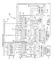
- FIG. 1 there is shown an example of a block diagram of a floating point arithmetic circuit 10 which may be used in conjunction with the present invention.
- the execution of floating point arithmetic utilizes such a circuit because of the specific algorithms which must be performed to determine the proper results.
- This circuit presumes that the floating point numbers have been prearranged according to a particular format, where the most significant bit represents the sign of the floating point number, and wherein a group of the next-most significant bits represent the exponent of t he floating point number, and wherein the remaining bits represent the fraction value of the number; i.e., the fraction value presuming that the binary point is placed at the left-most end of the fraction value.
- the hardware registers and logic associated with Fig. 1 include four additional bits; the I bit occupies the most significant position in the fraction field, and the G, R and S bits respectively occupy the least significant bit positions in the fraction field.
- Floating point operands cannot be added to or subtracted from each other unless their exponents are equal. This requires that their exponents be compared, and the operand fraction with the smaller exponent be shifted right the amount of the exponent difference. The fractions can then be added or subtracted with the larger exponent as the result exponent. Multiplication of floating point operands requires that the exponents be added and the fractions multiplied. Division of floating point operands requires that the divisor exponent b e subtracted from the dividend exponent and the dividend fraction be divided by the divisor fraction.
- the floating point arithmetic circuit of Fig. 1 can support both single and double precision arithmetic operations. It is designed to support a floating point add or subtract operation. It should be noted that Applicant's invention will work with circuits which implement other floating point formats.
- the floating point arithmetic circuit 10 of Fig. 1 utilizes a storage data bus 12 for receiving and transmitting data from other sources, such as a data processing system or the like. Information received over data storage bus 12 may be transmitted into a plurality of floating point registers 14. Floating point registers 1 4 may transmit information to an FA register 16, an FB register 18, or an FC register 22. FA register 16 may also transmit information back to floating point registers 14.
- the FA register 16 is a destination register for data from the floating point registers 14, and is the source register for data being transmitted to the floating point registers 14.
- the FA register 16 is also the source register for data which may be transferred to a memory via storage data bus 12, and it is a destination register for data transmitted from a carry-propagate adder 30, an exponent adder 20, and from a normalize-round circuit 34.
- the FA register 16 has outputs to a multiple selector 24, a prealigner circuit 26, a normalize-round circuit 34, and the exponent adder 20.
- the FA register 16 contains the second operand for add, subtract, compare, multiply and divide operations.
- FA register 16 has a section 16a for holding the exponent of the floating point number, and a section 16b for holding the fraction portion of the floating point number.
- the FA register 16 has an input multiplexer circuit 15 associated there with. Multiplexer circuit 15 provides for the selective gating of the various inputs into register 16, under control of an activation signal A. Other registers in the floating point arithmetic circuit 10 have similar multiplexer input controls.
- a control logic circuit 11 generates all of the activation signals required for data interchange and processing operations within floating point arithmetic circuit 10.
- Control logic circuit 11 has a plurality of control signal outputs, designated A , each of which serve as control inputs to various circuits and registers. It is well within the skill of the art to understand the need and design for a control logic circuit 11, as well as the activation signals A which are required for the operation of floating point arithmetic circuit 10; accordingly, a detailed presentation of these circuits and signals is not provided herein.
- the FB register 18 is a destination register for data received from the storage data bus 12, the floating point registers 14, and is also a destination register for data from the carry-propagate adder 30, and from the normalize-round circuit 34. It has outputs to the multiple selector 24, the prealigner circuit 26, and the exponent adder 20.
- the FB register is used to contain the first operand for the add, subtract, compare and divide operations; it also contains the intermediate result of the add, subtract and multiply operations.
- the FB register 18 has a section 18a for containing the exponent value of the floating point number, and a section 18b for containing the fraction portion of the floating point number, and has an input multiplexer circuit 17 for gating data into the register under control of activation signals from control logic circuit 11.
- the FC register 22 is a destination register for data from memory via storage data bus 12, and a destination register for data from the carry-propagate adder 30 and from the normalize-round circuit 34. It is also the destination register from the floating point registers 14.
- the FC register 22 has outputs to the multiple selector 24, the prealigner circuit 26, and the normalize-round circuit 34.
- the FC register 22 is used to contain the first operand of the multiply operation , and it is the destination register for the result of a divide operation.
- An input multiplexer circuit 21 controls the gating of data into FC register 22, under control of activation signals from control logic circuit 11.
- the prealigner circuit 26 is used to pre-shift the fraction with the smaller exponent for the add and subtract operation, which is necessary to make the floating point operand exponents equal prior to an add or subtract operation.
- the prealigner circuit 26 has the capability to shift a floating point fraction right from 0 to as many positions necessary as required by the selected format for the floating point. If double precision arithmetic is being performed, the prealigner is capable of shifting f rom 0-55 bit positions.
- the prealigner circuit 26 has an output to the carry-propagate adder 30, and to the FC register 22.
- the multiple selector 24 is a logic circuit which generates multiples of the multiplicand for the multiply operation, and multiples of the divisor for the divide operation. For the divide operation, the multiples are decoded from the high-order bits of the dividend, or partial dividend, and of the divisor. The complement of the operand may be generated by the multiple selector when necessary.
- the multiple selector 24 receives data from the FA register 16, the FB register 18, and the FC register 22.
- the multiple selector 24 has outputs to the carry-save adder tree 28.
- the carry-save adder tree 28 will permit three operands to be added together at the same time. This permits the use of a divide algorithm which generates two quotient bits per iteration.
- the carry-save adder tree 28 receives data from the multiple selector 24, and transmits data to the carry-propagate adder 30.
- the carry-propagate adder 30 is a 57-bit adder, and has an input from the carry-save adder 28 for generating the partial product of a multiply operation or the partial dividend of a divide operation.
- the carry-propagate adder circuit 30 may also receive inputs from the prealigner circuit 26, the FA register 16, and the FB register 18.
- the carry-propagate adder has an output connection to the FA register 16 and the FB register 18.
- An input multiplexer circuit 29 controls the gating of data into carry-propagate adder 30, under control of activation signals A from control logic circuit 11.
- the normalize-round circuit 34 includes a normalize circuit 34a which is used to normalize the results of a floating point operation. For example, the result of a multiply operation may require a left-shift of 1-bit in order to normalize the fraction, and the result of an add or subtract operation may require left-shift of up to 54-bit positions.
- the normalize-round circuit 34 also includes a round circuit 34b, which contains an incrementor circuit, for use in certain rounding operations, where the result may have to be incremented by a value of 1 in the low-order bit position.
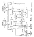
- Fig. 2 shows, very basically, t he apparatus used in prior art exponent adders or subtractors 20.
- Prior art exponent subtractors generally consisted of two adders 40 and 42. Each of the adders, 40 and 42, had a bit width equal to the exponent bit width designated by the particular format used to represent the floating point numbers. For example, in double precision floating point, an 11 bit adder is used since in that format 11 bits are devoted to the exponent portion of the number. There are other formats that devote additional bits to the exponent portion of the floating point number where larger adders would be needed to accommodate the subtraction of exponents.
- the first exponent and the 2's complement of the second exponent are added in adder 40 while the second exponent and the 2's complement of the first exponent are added in adder 42.
- adder 40 By adding the 2's complement of one of the exponents to the other exponent, this effectively yields the difference between the two exponents .
- These two operations are done in parallel.
- the sign or carries of each difference are then checked so that the difference which represented the smaller exponent subtracted from the larger exponent can be selected. Once this difference is determined, the fraction of the number having the smaller exponent is shifted to the right by the number of places determined by the difference between the exponents.
- exponent A is cleaved into two portions, a high portion designated by box 52, and a low portion, designated by box 54.
- the low portion 54 represents a certain number of lesser significant bits.
- the high portion 52 represents a certain number of the more significant bits.
- AH represents the bits associated with the high portion 52 of Exponent A
- AL represents the bits associated with t he low portion 54 of Exponent A.
- Exponent B is cleaved into two portions, a high portion 56 and a low portion 58. These portions are also designated BH and BL in other areas of Fig. 3.
- BH represents the bits associated with the high port ion of Exponent B
- BL represents the bits associated with the low portion of Exponent B.
- the apparatus 50 for determining the difference between two exponents also includes an adder 60 and an adder 62. In these adders, the differences (AL - BL) and (BL - AL) are determined. Also, from one of the adders a carry out signal 64 is output. In Fig. 3, the carry signal 64 is shown as output from adder 60. It should be noted that the carry signal could be output from adder 62 and the apparatus 50 would be equally effective in determining the difference between the exponents.
- the compare circuit 66 can be realized by either using a circuit with one adder, a circuit with two adders, or a circuit with two incrementors. Referring to Fig. 4, the latter type of compare circuit 66 is shown and includes an incrementors 92 and an incrementor 94.
- the compare circuit 66 also includes three comparators 96, 98, and 100. The signals representing AH and BH are input to comparator 96 to determine if they are equal. If they are not equal comparator 96 does not produce an output.
- the signal AH is also input to incrementor 92 which adds one to the bit stream represented by AH.
- the apparatus also includes a select high circuit 67.
- the select high circuit 67 determines whether BH > AH or AH > BH.
- the circuit also selects the higher number A or B.
- Such a circuit can be implemented in a number of ways.
- Two selectors each having the three way NOR as an input, and one having an input when AH > BH and one having an input when BH > AH would be used to select the higher of A or B.
- An adder 69 can be used to determine if AH or BH is highe r. The carry from the difference of either AH - BH or BH - AH will determine which floating point number is higher.
- the apparatus 50 also includes several selectors 68, 70 and 72, and a mux 74.
- Selector 72 selects the fraction portion which will be shifted.
- the mux 74 selects the proper difference between the exponents A and B. Inputs to the mux 74 include the output from selector 68 and the output from selector 70 as well as the output from adder 60 and the output from adder 62. From these various inputs the mux 74 selects the amount of difference between the exponents so the proper right shift of the fraction portion of the smaller floating point number occurs.
- the invention is based on the premise that if the fraction portion of the smaller floating point number has to be shifted right more places than the width of the fraction portion of the floating point number in order to add the numbers, the effect of adding the smaller floating point number will be the same as adding a zero. In other words, if the difference in the exponent s indicates that a shift of more spaces than the number of bits devoted to the fraction portion of the floating point number is required, then the smaller number need not be added to the larger number. The effect of adding the smaller to the larger n umber would be very small.
- the floating point exponent portion of each of the numbers being added or subtracted is divided into a high portion and a low portion.
- the low portion is selected so that the highest number that could be represented would be equal to or more than the number of bits devoted to the fraction portion of the floating point number of the format the particular numbers are in. For example, in the double precision format for floating point numbers 53 bits are devoted to the fraction portion of the number.
- the low portion is set at six bits since the highest possible number represented by six bits is 63 which is greater than 53. If only five bits were used then the highest possible number represented would only be 31 which would be inadequate since 31 is less than 53.
- the number of bits required to be in the lower portion of each exponent portion equals the LOG 2 [(# of bits devoted to the fraction)].
- the number of bit s in the lower portion has to be an integer number so this number is always rounded up to the next highest integer.
- the number of bits devoted to the high portion of each exponent is equal to the [(number of exponent bits) - (number o f bits for the lower portion)].
- the differences which require a shift in the fraction can be determined.
- the difference between the high portions of the two exponents must be either 0 or 1. Any other difference would indicate a shift of greater than the number of places devoted to the fraction portion of the floating point number. In that case, the larger floating point number A or B is selected as the answer of A + B. Select high circuit 67 is used to select the higher floating point number.
- the six least significant bits of the exponent portion are designated as the bits in the lower portion.
- the higher portion of the exponent would include the five most significant bits of the exponent portion of each of the floating point numbers. If the difference between the higher portions of two floating point numbers is 1, that would correspond to a difference of 64. The largest difference between the exponents would then be equal to [127, (64 + 63)] and the smallest difference would be 1 (64 - 63) since the largest difference in the lower portion can be at most 63. If the difference in the higher portion is 2 that would correspond to a difference of 128. Now the smallest difference would be 128 - 63 which equals 65.
- a bit shift of 65 is more than the fractional portion of the floating point number in double precision format (53 bits are the maximum) and, therefore, adding the smaller floating point number to the larger would yield the same result as adding zero to the larger floating point number.
- the hardware shown in Fi g. 3 and Fig. 4 implements the conditions stated in the above table.
- the compare circuit shown in Fig. 4 compares AH to BH, (AH + 1) to BH, and (BH + 1) to AH.
- Selectors 68, 70 and 72 and MUX 74 are realized us ing 2 X 2 AND-OR gates. It should be noted that the functions of these selectors and the MUX could also be realized using other combinations and sizes of AND-OR gates.
- MUX 74 acts to gate the proper difference, eit her (AL - BL) or (BL - AL), determined by either the adder 60 or the adder 62 in response to a signal from either selector 68 or selector 70.
- the output of adders 60 and 62 are both input to the MUX 74.
- MUX 74 will select the quantity AL - BL in the presence of a signal from the selector 68 and will select the quantity BL - AL in the presence of a signal from the selector 70.
- the output of MUX 74 indicates the proper exponent difference which indicates the proper number of positions to shift th e binary point in a floating point number.
- the invention speeds up the process of determining the difference between two exponents which is necessary in order to add or subtract two floating point numbers.
- I t is well known that carries propagating across the bits in an adder is the major factor in slowing down an adder. It is also known that a narrower adder is quicker than a wider adder since the carry will not propagate across as many bits.
- the invention splits the exponent portion of each of the floating point numbers into two sections and uses narrower adders to determine the difference. This limits the number of carries that propagate across an adder which in turn cuts down t he time consumed in the operation of determining the difference between two exponents when compared to prior methods and apparatus which use adders of the same width as the exponent to determine the difference between two exponents.
Landscapes
- Engineering & Computer Science (AREA)
- Physics & Mathematics (AREA)
- General Physics & Mathematics (AREA)
- Computational Mathematics (AREA)
- Computing Systems (AREA)
- Mathematical Analysis (AREA)
- Mathematical Optimization (AREA)
- Pure & Applied Mathematics (AREA)
- Theoretical Computer Science (AREA)
- Nonlinear Science (AREA)
- General Engineering & Computer Science (AREA)
- Complex Calculations (AREA)
Applications Claiming Priority (2)
| Application Number | Priority Date | Filing Date | Title |
|---|---|---|---|
| US46962890A | 1990-01-24 | 1990-01-24 | |
| US469628 | 1990-01-24 |
Publications (2)
| Publication Number | Publication Date |
|---|---|
| EP0438962A2 true EP0438962A2 (de) | 1991-07-31 |
| EP0438962A3 EP0438962A3 (en) | 1992-03-18 |
Family
ID=23864482
Family Applications (1)
| Application Number | Title | Priority Date | Filing Date |
|---|---|---|---|
| EP19900480228 Withdrawn EP0438962A3 (en) | 1990-01-24 | 1990-12-28 | Method and apparatus for exponent adder |
Country Status (2)
| Country | Link |
|---|---|
| EP (1) | EP0438962A3 (de) |
| JP (1) | JPH0748176B2 (de) |
Cited By (1)
| Publication number | Priority date | Publication date | Assignee | Title |
|---|---|---|---|---|
| EP0474247A3 (en) * | 1990-09-07 | 1993-04-07 | Nec Corporation | Shift amount floating-point calculating circuit with a small amount of hardware and rapidly operable |
Family Cites Families (4)
| Publication number | Priority date | Publication date | Assignee | Title |
|---|---|---|---|---|
| US2949231A (en) * | 1958-02-24 | 1960-08-16 | Westinghouse Electric Corp | Arithmetic unit for floating radix notation |
| US3993891A (en) * | 1975-07-03 | 1976-11-23 | Burroughs Corporation | High speed parallel digital adder employing conditional and look-ahead approaches |
| US4310879A (en) * | 1979-03-08 | 1982-01-12 | Pandeya Arun K | Parallel processor having central processor memory extension |
| US4858165A (en) * | 1987-06-19 | 1989-08-15 | Digital Equipment Corporation | Apparatus and method for acceleration of effective subtraction procedures by the approximation of the absolute value of the exponent argument difference |
-
1990
- 1990-12-21 JP JP2413158A patent/JPH0748176B2/ja not_active Expired - Lifetime
- 1990-12-28 EP EP19900480228 patent/EP0438962A3/en not_active Withdrawn
Cited By (1)
| Publication number | Priority date | Publication date | Assignee | Title |
|---|---|---|---|---|
| EP0474247A3 (en) * | 1990-09-07 | 1993-04-07 | Nec Corporation | Shift amount floating-point calculating circuit with a small amount of hardware and rapidly operable |
Also Published As
| Publication number | Publication date |
|---|---|
| JPH0748176B2 (ja) | 1995-05-24 |
| JPH04213110A (ja) | 1992-08-04 |
| EP0438962A3 (en) | 1992-03-18 |
Similar Documents
| Publication | Publication Date | Title |
|---|---|---|
| US4941120A (en) | Floating point normalization and rounding prediction circuit | |
| US4926370A (en) | Method and apparatus for processing postnormalization and rounding in parallel | |
| EP0483864B1 (de) | Hardware-Anordnung zur Addition und Subtraktion von Gleitkommazahlen | |
| US6529928B1 (en) | Floating-point adder performing floating-point and integer operations | |
| US6099158A (en) | Apparatus and methods for execution of computer instructions | |
| US4999803A (en) | Floating point arithmetic system and method | |
| US6446104B1 (en) | Double precision floating point multiplier having a 32-bit booth-encoded array multiplier | |
| EP0040279B1 (de) | Binärer Dividierer | |
| EP0472139A2 (de) | Gleitkommaprozessor | |
| JP2002108606A (ja) | スティッキービット生成回路及び乗算器 | |
| JPS584441A (ja) | デ−タ処理システム | |
| JPH01112332A (ja) | 乗算及び算術論理演算機能を組合わせて使用する浮動小数点ユニット | |
| US5117384A (en) | Method and apparatus for exponent adder | |
| US20050228844A1 (en) | Fast operand formatting for a high performance multiply-add floating point-unit | |
| US4996660A (en) | Selection of divisor multipliers in a floating point divide circuit | |
| US4979142A (en) | Two-bit floating point divide circuit with single carry-save adder | |
| US6061707A (en) | Method and apparatus for generating an end-around carry in a floating-point pipeline within a computer system | |
| US7401107B2 (en) | Data processing apparatus and method for converting a fixed point number to a floating point number | |
| EP0332215B1 (de) | Operationsschaltung für auf die Fliesskommadarstellung basierenden Operanden | |
| US5150319A (en) | Circuitry for rounding in a floating point multiplier | |
| US7080112B2 (en) | Method and apparatus for computing an approximation to the reciprocal of a floating point number in IEEE format | |
| US7437400B2 (en) | Data processing apparatus and method for performing floating point addition | |
| EP0438962A2 (de) | Verfahren und Gerät zur Addition von Exponenten | |
| US7003540B2 (en) | Floating point multiplier for delimited operands | |
| EP0064826A2 (de) | Arithmetische Einheit mit Rundung der Gleitkommaergebnisse in einem Datenverarbeitungssystem |
Legal Events
| Date | Code | Title | Description |
|---|---|---|---|
| PUAI | Public reference made under article 153(3) epc to a published international application that has entered the european phase |
Free format text: ORIGINAL CODE: 0009012 |
|
| AK | Designated contracting states |
Kind code of ref document: A2 Designated state(s): DE FR GB |
|
| 17P | Request for examination filed |
Effective date: 19911112 |
|
| PUAL | Search report despatched |
Free format text: ORIGINAL CODE: 0009013 |
|
| AK | Designated contracting states |
Kind code of ref document: A3 Designated state(s): DE FR GB |
|
| 17Q | First examination report despatched |
Effective date: 19960315 |
|
| STAA | Information on the status of an ep patent application or granted ep patent |
Free format text: STATUS: THE APPLICATION IS DEEMED TO BE WITHDRAWN |
|
| 18D | Application deemed to be withdrawn |
Effective date: 19970103 |