EP0439105A1 - Einziehbarer Prellblock für Laufkran oder Kran - Google Patents
Einziehbarer Prellblock für Laufkran oder Kran Download PDFInfo
- Publication number
- EP0439105A1 EP0439105A1 EP91100723A EP91100723A EP0439105A1 EP 0439105 A1 EP0439105 A1 EP 0439105A1 EP 91100723 A EP91100723 A EP 91100723A EP 91100723 A EP91100723 A EP 91100723A EP 0439105 A1 EP0439105 A1 EP 0439105A1
- Authority
- EP
- European Patent Office
- Prior art keywords
- crane
- supporting structure
- runways
- overhead traveling
- pair
- Prior art date
- Legal status (The legal status is an assumption and is not a legal conclusion. Google has not performed a legal analysis and makes no representation as to the accuracy of the status listed.)
- Withdrawn
Links
- 239000000872 buffer Substances 0.000 title claims abstract description 44
- 230000003014 reinforcing effect Effects 0.000 description 2
- 238000003723 Smelting Methods 0.000 description 1
- 229910000831 Steel Inorganic materials 0.000 description 1
- 230000000903 blocking effect Effects 0.000 description 1
- 238000005266 casting Methods 0.000 description 1
- 230000008878 coupling Effects 0.000 description 1
- 238000010168 coupling process Methods 0.000 description 1
- 238000005859 coupling reaction Methods 0.000 description 1
- 230000001419 dependent effect Effects 0.000 description 1
- 239000004579 marble Substances 0.000 description 1
- 230000011664 signaling Effects 0.000 description 1
- 239000010959 steel Substances 0.000 description 1
- 239000004575 stone Substances 0.000 description 1
- 230000007306 turnover Effects 0.000 description 1
Images

Classifications
-
- B—PERFORMING OPERATIONS; TRANSPORTING
- B66—HOISTING; LIFTING; HAULING
- B66C—CRANES; LOAD-ENGAGING ELEMENTS OR DEVICES FOR CRANES, CAPSTANS, WINCHES, OR TACKLES
- B66C7/00—Runways, tracks or trackways for trolleys or cranes
- B66C7/16—Devices specially adapted for limiting trolley or crane travel; Arrangements of buffer-stops
Definitions
- the present invention relates to a buffer device for an overhead traveling crane or for a crane.
- the present invention relates to a retractable buffer device for overhead traveling crane which is suitable for being placed on the path of an overhead traveling crane or of a crane in order to selectively limit its run as far as it reaches a predetermined position, or to allow its advancement beyond said position.
- Said device may mainly applied in the application fields of overhead traveling devices such as, for instance, in the fields of mechanical industries, heavy loads transportation, stone and/or marble working etc.
- Such buffers are always placed close to the ends of the runways on which, for instance, a bridge crane is made to move and they are suitable for cushioning possible impacts against said ends which are by way of example due to a misuse of the bridge crane, or to a failure of the same.
- Such a situation may occur, for example, in the case of the hot zone of a steel plant, in which the overhead traveling crane is used for transporting a ladle towards, respectively, the smelting furnace zone, the casting zone or the mantainance zone, these zones being separated from each other.
- the known buffers involve disadvantages and drawbacks due to the fact that they may only be used, in these cases, at the ends of the runways, and they may clearly not give any help in the case where the overhead traveling crane is inadvertently or by failure moved towards a separating wall striking against it and possibly damaging it.
- the device comprises a buffer structure which is assembled in a predetermined position on the runways of an overhead traveling crane, said structure being rotatably movable by means of a motor between a first limit position, in which the buffer is placed in such a way as to interfere with the advancing movement of the overhead traveling crane beyond said predetermined position, and a second limit position, in which said structure is retracted behind said runways and allows the advancing movement of the overhead traveling crane beyond said predetermined position.
- the movable structure of the buffer device is provided with a pair of trap doors which are movable with it and which allow the passage of operators on a gangway disposed adjacent to the runways both in the active and the retracted positions of the buffer.
- the buffer device according to the invention is provided with a telescopic buffer element, which allows the device to be rotatably moved also in limited room conditions, such as for instance between a pair of adjacent beams.
- the device according to the invention allows a plurality of advantages to be achieved in respect of the known devices, since it may be placed in any position along the runways, thus limiting at will the overhead traveling crane advancing movement.
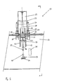
- reference sign 10 generally indicates a retractable buffer device according to the present invention.
- Said device 10 is assembled on supporting elements which are constituted by a pair of L-shaped flanges 11, 12 which are fixed, generally by means of nuts and bolts, to a beam 13 on which a runway 14, in this case a sliding rail for an overhead traveling crane (not represented in the figures), is formed.
- a hole is disposed close to one end of both flanges 11, 12 and acts as a support for a first pivot 15 serving as turnover hinge for device 10.
- Said device 10 comprises a structure 16 forming a frame and comprising a pair of elements 17, 18 which support a pair of buffers 19, 25, each element 17, 18 of said pair being further provided with an extension 20 on which is supported a second pivot 21 on which acts the movable arm 22 of an hydraulic and/or pneumatic jack 23, whose base is pivoted on a hinge 24 which is fixed to said beam 13.
- said structure 16 is fixed to said first pivot 15 and may be freely rotated about it in the directions which are indicated by the curved line X following to the operation of the movable arm 22 of jack 23, between a first, retracted, position, which is indicated by means of dashed lines in figure 2, and a second, active, position, which is indicated by continuous lines in fig. 2.
- a pair of telescopic buffer elements 19, 25 Fixed to said supporting structure 16 are a pair of telescopic buffer elements 19, 25 and, respectively, a blocking device formed by a pair of vices which may be hydraulically and/or pneumatically operable in a way which will be in detail hereinafter described.
- the pair of telescopic buffers 19, 25 generally comprises a fixed buffer element 25, which is integral with the supporting structure 16, and a movabler buffer element 19, which is able to slide inside of said fixed element 25.
- the movable buffer element 19 may be moved by means of an hydraulic and/or pneumatical jack 28, whose base is supported on the base of the fixed buffer element 25 and whose movable arm is fixed close to one end of the movable buffer element 19.
- the device for fastening the buffer to the runway 13 comprises a pair of vices 26, 27, each of these being constituted by an elongated element in which:
- the device 10 is provided with a pair of trap doors, one of which (37) is indicated by dashed lines in figure 2.
- Said trap doors 37 are respectively placed at both sides of device 10 and play the role, which will be hereinafter described in detail, of allowing the passage of an operator on a gangway (not represented) which is disposed parallel to the runway 13, both in the cases where the buffer is in its active position, and where it is in its retracted position beneath the runway 13.
- the device 10 is finally completed by a series of signalization and safety devices which include, for instance, semaphores 38, roto-alarm 39, syrens 40, limit switches and magnetical devices for detecting the presence of people (not represented).
- signalization and safety devices include, for instance, semaphores 38, roto-alarm 39, syrens 40, limit switches and magnetical devices for detecting the presence of people (not represented).
- the operation of the retractable buffer device 10 according to the invention is as follows.
- the buffer element 25 is supported on railway 13, while a second trap door is made to close the passage hole of device 10 is such a way as to allow the passage of an operator on the gangway.
- vices 26, 27 are operated by means of a command on movable arm 33 of jack 34; the extension of movable arm 33 causes the extension of the adjustable connecting rods 31, 32, which are made to exert a thrust on the pivot 30 which is carried by each vice 26, 27.
- the placing operation of the buffer is completed, the semaphore 38 indicates a red light, the limit switches are switched on and the other signalling devices are switched off.
- the operating sequence described above is performed in a lapse of time of about thirty seconds.
- a laps of time of about thirty seconds is necessary for the reverse sequence, i.e. for retracting the buffer beneath the runway.
- the device is provided with a single trap door 37 for opening/closing the buffer passage hole, said trap door being directly hinged to the gangway and automatically operable by means of a hydraulic and/or pneumatic jack at the beginning of a positioning manoeuver of the buffer.
- means for moving the device or parts thereof which are different from those described above may be adopted, e.g. helical gear or rack couplings.
Landscapes
- Engineering & Computer Science (AREA)
- Mechanical Engineering (AREA)
- Vibration Dampers (AREA)
Applications Claiming Priority (2)
| Application Number | Priority Date | Filing Date | Title |
|---|---|---|---|
| IT84905A IT1239299B (it) | 1990-01-25 | 1990-01-25 | Dispositivo respingente a scomparsa per carro ponte o gru. |
| IT8490590 | 1990-01-25 |
Publications (1)
| Publication Number | Publication Date |
|---|---|
| EP0439105A1 true EP0439105A1 (de) | 1991-07-31 |
Family
ID=11325506
Family Applications (1)
| Application Number | Title | Priority Date | Filing Date |
|---|---|---|---|
| EP91100723A Withdrawn EP0439105A1 (de) | 1990-01-25 | 1991-01-22 | Einziehbarer Prellblock für Laufkran oder Kran |
Country Status (2)
| Country | Link |
|---|---|
| EP (1) | EP0439105A1 (de) |
| IT (1) | IT1239299B (de) |
Cited By (3)
| Publication number | Priority date | Publication date | Assignee | Title |
|---|---|---|---|---|
| RU2234454C2 (ru) * | 2002-11-27 | 2004-08-20 | Закрытое акционерное общество Центральный научно-исследовательский проектно-экспериментальный институт организации, механизации и технической помощи строительству | Предохранительное устройство упор тупиковый многоступенчатый |
| RU2248318C2 (ru) * | 2002-11-19 | 2005-03-20 | Закрытое акционерное общество Центральный научно-исследовательский проектно-экспериментальный институт организации, механизации и технической помощи строительству (ЗАО ЦНИИОМТП) | Упор тупиковый |
| RU2253583C2 (ru) * | 2003-01-27 | 2005-06-10 | Закрытое акционерное общество "Ресурс" | Тупиковый упор |
Citations (6)
| Publication number | Priority date | Publication date | Assignee | Title |
|---|---|---|---|---|
| DE296563C (de) * | ||||
| DE1196334B (de) * | 1962-03-23 | 1965-07-08 | Pohlig Heckel Bleichert | Prellbock fuer Hebezeuge oder Foerdergeraete |
| GB1108863A (en) * | 1965-08-13 | 1968-04-03 | Godwin Warren Eng | Improvements in or relating to retractable buffer stop assemblies |
| DE2710965A1 (de) * | 1977-03-12 | 1978-09-14 | Erhart Dr Wilisch | Prellbock zum zeitweiligen absperren von durchgangsgleisen |
| GB2056389A (en) * | 1979-08-13 | 1981-03-18 | Wilisch E | Buffer stop, especially as a train leading end safety means in a shunting station |
| FR2542295A1 (fr) * | 1983-03-07 | 1984-09-14 | Smie | Butee de fin de rail de chemin de roulement |
-
1990
- 1990-01-25 IT IT84905A patent/IT1239299B/it active IP Right Grant
-
1991
- 1991-01-22 EP EP91100723A patent/EP0439105A1/de not_active Withdrawn
Patent Citations (6)
| Publication number | Priority date | Publication date | Assignee | Title |
|---|---|---|---|---|
| DE296563C (de) * | ||||
| DE1196334B (de) * | 1962-03-23 | 1965-07-08 | Pohlig Heckel Bleichert | Prellbock fuer Hebezeuge oder Foerdergeraete |
| GB1108863A (en) * | 1965-08-13 | 1968-04-03 | Godwin Warren Eng | Improvements in or relating to retractable buffer stop assemblies |
| DE2710965A1 (de) * | 1977-03-12 | 1978-09-14 | Erhart Dr Wilisch | Prellbock zum zeitweiligen absperren von durchgangsgleisen |
| GB2056389A (en) * | 1979-08-13 | 1981-03-18 | Wilisch E | Buffer stop, especially as a train leading end safety means in a shunting station |
| FR2542295A1 (fr) * | 1983-03-07 | 1984-09-14 | Smie | Butee de fin de rail de chemin de roulement |
Cited By (3)
| Publication number | Priority date | Publication date | Assignee | Title |
|---|---|---|---|---|
| RU2248318C2 (ru) * | 2002-11-19 | 2005-03-20 | Закрытое акционерное общество Центральный научно-исследовательский проектно-экспериментальный институт организации, механизации и технической помощи строительству (ЗАО ЦНИИОМТП) | Упор тупиковый |
| RU2234454C2 (ru) * | 2002-11-27 | 2004-08-20 | Закрытое акционерное общество Центральный научно-исследовательский проектно-экспериментальный институт организации, механизации и технической помощи строительству | Предохранительное устройство упор тупиковый многоступенчатый |
| RU2253583C2 (ru) * | 2003-01-27 | 2005-06-10 | Закрытое акционерное общество "Ресурс" | Тупиковый упор |
Also Published As
| Publication number | Publication date |
|---|---|
| IT9084905A0 (it) | 1990-01-25 |
| IT9084905A1 (it) | 1991-07-26 |
| IT1239299B (it) | 1993-10-19 |
Similar Documents
| Publication | Publication Date | Title |
|---|---|---|
| US5773771A (en) | Apparatus for preventing unintended movement of elevator car | |
| US5207024A (en) | Door system of the swivel-sliding type for use in an vehicle | |
| US7334314B2 (en) | Work treatment installation | |
| US3931951A (en) | Mobile pallet for an installation for production of pre-fabricated elements of concrete | |
| US4553743A (en) | Elevated device for placing slag retention means in tapping converters | |
| HK20388A (en) | Double sliding door, in particular a lift door | |
| US5277396A (en) | Casting mould | |
| US4308697A (en) | Floor plate assembly | |
| US5299508A (en) | Railroad car door closure having trackside mounted plural actuating arms | |
| ITGE20120055A1 (it) | "macchina risanatrice di massicciate ferroviarie con catena di scavo a frontale variabile" | |
| US5784965A (en) | Interlock mechanism for an overhead trackway system | |
| US2064405A (en) | Freight car appliances | |
| US3514991A (en) | Bender table assembly | |
| KR20020018652A (ko) | 피봇가능한 가이드 빔 스위치 | |
| US5360205A (en) | Driving assembly for slide gate on a metallurgical vessel | |
| JPH04228778A (ja) | プラットホーム上に自動車を駐車させるためのパーキング装置 | |
| RU1791131C (ru) | Устройство дл распалубки бортов формы | |
| ATE56188T1 (de) | Fahrzeugtuer, insbesondere fuer schienen und u-bahn-personenwagen. | |
| JP2659615B2 (ja) | 圧気式シールドにおけるロックドアの開閉方法および開閉装置 | |
| EP0439104B1 (de) | Mobile Wand | |
| SU1011755A1 (ru) | Устройство дл подъема рельсошпальной решетки железнодорожного пути | |
| SU1743955A1 (ru) | Устройство дл закрывани крышек люков полувагонов | |
| DE3814351C2 (de) | ||
| SU1458522A1 (ru) | Трансформируемое ограждение промышленного здани ,оборудованного мостовым краном | |
| CA2070844A1 (en) | Apparatus for unloading from an open freight car |
Legal Events
| Date | Code | Title | Description |
|---|---|---|---|
| PUAI | Public reference made under article 153(3) epc to a published international application that has entered the european phase |
Free format text: ORIGINAL CODE: 0009012 |
|
| AK | Designated contracting states |
Kind code of ref document: A1 Designated state(s): AT BE CH DE DK ES FR GB GR IT LI LU NL SE |
|
| 17P | Request for examination filed |
Effective date: 19920120 |
|
| 17Q | First examination report despatched |
Effective date: 19930323 |
|
| STAA | Information on the status of an ep patent application or granted ep patent |
Free format text: STATUS: THE APPLICATION IS DEEMED TO BE WITHDRAWN |
|
| 18D | Application deemed to be withdrawn |
Effective date: 19931207 |