EP0439207A2 - Hinterräderlenkungsapparat mit Ausrichtungsfehlerkompensation - Google Patents
Hinterräderlenkungsapparat mit Ausrichtungsfehlerkompensation Download PDFInfo
- Publication number
- EP0439207A2 EP0439207A2 EP91200022A EP91200022A EP0439207A2 EP 0439207 A2 EP0439207 A2 EP 0439207A2 EP 91200022 A EP91200022 A EP 91200022A EP 91200022 A EP91200022 A EP 91200022A EP 0439207 A2 EP0439207 A2 EP 0439207A2
- Authority
- EP
- European Patent Office
- Prior art keywords
- steering
- rear wheel
- toe
- toe error
- command
- Prior art date
- Legal status (The legal status is an assumption and is not a legal conclusion. Google has not performed a legal analysis and makes no representation as to the accuracy of the status listed.)
- Granted
Links
- 238000005259 measurement Methods 0.000 claims 3
- 230000005540 biological transmission Effects 0.000 claims 1
- 230000007246 mechanism Effects 0.000 abstract description 6
- 238000010586 diagram Methods 0.000 description 6
- 238000000034 method Methods 0.000 description 6
- 238000006073 displacement reaction Methods 0.000 description 3
- 238000004590 computer program Methods 0.000 description 1
- 230000000694 effects Effects 0.000 description 1
- 230000000977 initiatory effect Effects 0.000 description 1
- 238000004904 shortening Methods 0.000 description 1
- 239000000725 suspension Substances 0.000 description 1
Images

Classifications
-
- B—PERFORMING OPERATIONS; TRANSPORTING
- B62—LAND VEHICLES FOR TRAVELLING OTHERWISE THAN ON RAILS
- B62D—MOTOR VEHICLES; TRAILERS
- B62D7/00—Steering linkage; Stub axles or their mountings
- B62D7/06—Steering linkage; Stub axles or their mountings for individually-pivoted wheels, e.g. on king-pins
- B62D7/14—Steering linkage; Stub axles or their mountings for individually-pivoted wheels, e.g. on king-pins the pivotal axes being situated in more than one plane transverse to the longitudinal centre line of the vehicle, e.g. all-wheel steering
- B62D7/15—Steering linkage; Stub axles or their mountings for individually-pivoted wheels, e.g. on king-pins the pivotal axes being situated in more than one plane transverse to the longitudinal centre line of the vehicle, e.g. all-wheel steering characterised by means varying the ratio between the steering angles of the steered wheels
- B62D7/159—Steering linkage; Stub axles or their mountings for individually-pivoted wheels, e.g. on king-pins the pivotal axes being situated in more than one plane transverse to the longitudinal centre line of the vehicle, e.g. all-wheel steering characterised by means varying the ratio between the steering angles of the steered wheels characterised by computing methods or stabilisation processes or systems, e.g. responding to yaw rate, lateral wind, load, road condition
-
- B—PERFORMING OPERATIONS; TRANSPORTING
- B62—LAND VEHICLES FOR TRAVELLING OTHERWISE THAN ON RAILS
- B62D—MOTOR VEHICLES; TRAILERS
- B62D17/00—Means on vehicles for adjusting camber, castor, or toe-in
Definitions
- the present invention is directed to a rear wheel steering apparatus, and more particularly to apparatus which individually compensates for the toe error of each rear wheel.
- Vehicles with four wheel independent suspensions generally require the adjustment of rear toe angles during the wheel alignment process. This adjustment typically involves manually lengthening or shortening a toe-link bar with a wrench to effect sufficient inward or outward toe movement to bring the toe angles within a specified error window.
- Apparatus in accordance with the present invention is characterised by the features specified in the characterising portion of Claim 1.
- the present invention is directed to an improved apparatus in which a rear wheel steering mechanism capable of independently positioning the rear wheels of a vehicle also independently corrects the toe error of each steered wheel.
- each rear wheel is steered by a separate actuator.
- the steering command for the actuators is determined at least in relation to the front steering angle, the command being constrained within predefined command limits.
- the actuators on the other hand, have a control range which exceeds that of the predefined command limits.
- the control unit which generates the steering commands is adapted to receive and store signals representing the toe error of each rear wheel from a conventional wheel alignment machine, and the control unit causes the actuator to position each rear wheel as a combined function of the steering command and the respective stored toe error signals.
- an alignment machine When realignment becomes necessary, an alignment machine is connected to the control unit, and the apparatus enters a reset mode in which the rear wheels are steered to a "straight ahead" position independent of the previously stored toe error values, and the newly measured toe error values are stored for future steering control.
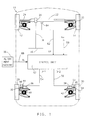
- the reference numeral 10 generally designates a motor vehicle having four steerable wheels suspended from the vehicle on conventional ball joint mechanisms.
- the front wheels 12, 14 are steered together in response to rotation of an operator manipulated handwheel 16.
- the handwheel 16 is mechanically connected via steering column 18 to a pinion gear 20, which is maintained in meshing engagement with teeth formed on a rack member 22.
- the rack member 22, is connected to the front wheel steering knuckles 24 and 26, completing the mechanical linkage connecting the front wheels 12, 14 to the handwheel 16.
- the steering of the front wheels 12, 14 may be assisted by a conventional hydraulic power assist steering system or by an electric power assist system, such as that shown in the US-A-4,509,611.
- the rear wheels 28, 30 are also provided with steering knuckles 32, 34 for effecting limited independent positive and negative steering of the same.
- Each rear wheel assembly includes a linear actuator 36, 38 mounted on a lower control arm 40, 42 and having an output linkage 44, 46 connected to the respective steering knuckles 32, 34.
- Each such output linkage 44, 46 is axially displaceable by an electric motor 48, 50, operating through a generally conventional ball-screw mechanism (not shown).
- a computer-based control unit 52 develops separate position control signal Dr1 and Dr2 for the rear wheels 28 and 30, and applies such signals to the electric motors 48 and 50 via lines 54 and 56.
- electrical signals indicative of vehicle speed Nv and front wheel steering angle Df are supplied as inputs to control unit 52 via lines 58 and 62.
- the vehicle speed signal Nv may be obtained with a conventional variable reluctance magnetic speed pickup (not shown), and the front steering angle signal Df may be obtained with a conventional position sensor 64 responsive to the displacement of rack member 22. Additional position sensors responsive to the displacement of the actuator output linkages 44, 46 may also be provided for control purposes if desired.
- the control unit 52 develops a single overall rear wheel steering command Dr as a function of the front wheel steering angle Df and the vehicle speed Nv.
- the individual rear actuator commands Dr1 and Dr2 are then determined according to the difference of the steering command Dr and stored toe error signals for each rear wheel 28, 30.
- Dr1 Dr - TE1
- Dr2 Dr - TE2 where TE1 and TE2 represent the toe error values for the rear wheels 28 and 30, respectively.
- An alignment machine designated by the reference numeral 66 measures the toe error of each rear wheel 28, 30 and communicates the error information to control unit 52 via a serial data bus 68.
- the alignment machine 66 represents equipment installed at the final assembly point of the motor vehicle 10; later, the alignment machine 66 may be a dealer or service station installed alignment apparatus. In either event, the alignment machine 66 measures the toe error of each rear wheel 28, 30 and transmits a corresponding signal AL to control unit 52 in accordance with a predefined protocol. In response, the control unit 52 enters a calibration mode in which the rear wheels 28,30 are steered to a straight (zero steering angle) position, independent of the previously stored toe error values, if any.
- the control unit 52 stores the toe error values transmitted by the alignment machine 66, completing the alignment procedure. Once the alignment machine 66 is disconnected from the control unit 52, the normal control mode is entered, and the rear wheels 28,30 are steered as a combined function of the normal overall steering command Dr and the respective stored toe error signals TE1, TE2.
- the line diagram of Figure 2 defines three related steering movements: the required system movement (RSM), the electronically recognized movement (ERM), and the mechanically possible movement (MPM).
- the RSM is the actuator movement range required for the normal rear wheel steering function.
- the ERM is the actuator movement range which the control unit 52 is capable of commanding. Since the ERM is greater than the RSM, the control unit 52 can command a steering angle which is greater than the most severe steering command Dr generated in normal rear wheel steer operation. This enables the control unit 52 to compensate for a toe error opposite in sign to the steering command Dr, even under the most severe steering situations.
- the MPM is the mechanical limit of actuator movement.
- the MPM is greater than the ERM in order to avoid steering operation in the area of the mechanical actuator limits.
- the RSM is sufficient to permit steering movement of ⁇ 4 degrees; the ERM is sufficient to permit steering movement of ⁇ 4.5 degrees; and the MPM is sufficient to permit steering movement of ⁇ 6 degrees.
- the flow diagram of Figure 3 represents program instructions executed by the computer-based control unit 52 in carrying out the control method of this invention.
- the block 70 designates a series of initialization instructions executed at the initiation of each period of vehicle operation for initializing the registers and variables used by control unit 52. Thereafter, the remaining blocks are sequentially and repeatedly executed as indicated by the flow diagram lines.
- the block 72 is executed to read the alignment signal AL and the inputs representing the measured vehicle speed Nv and front steering angle Df. If the alignment signal AL is active, as determined at block 74, the control enters a calibration mode in which the blocks 76 - 82 are executed to (1) set the toe error variables TE1, TE2 equal to the new toe error values encoded in the alignment signal AL, (2) look-up the "straight ahead" steering command Dr, (3) set the rear steer commands Dr1 and Dr2 equal to the steering command Dr, and (4) output the rear steering commands Dr1, Dr2 to the electric motors 48, 50.
- the steering command look-up refers to a conventional 3D look-up table technique in which the overall rear steer command Dr is stored as a combined function of the front steering angle Df and the vehicle speed Nv.
- the term Df is set to zero as indicated at block 78. This sequence of steps is repeated so long as the alignment signal AL is active.
- the control enters a normal steering mode in which the blocks 84 - 88 and 82 are executed to (1) look-up the normal overall steering command Dr as a function of the measured front steering angle Df and vehicle speed Nv, (2) look-up the stored toe error values TE1, TE2, (3) compute the rear steer commands Dr1 and Dr2 in relation to the normal overall steering command Dr and the toe error terms TE1 and TE2, respectively, and (4) output the rear steering commands Dr1, Dr2 to the electric motors 48, 50.
- the stored toe error values TE1, TE2 are combined with the overall steering command Dr, to thereby provide a continuous compensation for the toe errors of the individual rear wheels 28 and 30.
- a re-alignment Whenever re-alignment becomes necessary, the calibration procedure described above is simply repeated at a dealer or service station. Such a re-alignment may also involve a calibration of the rack position sensor 64 (depending on the sensor technology) to ensure that the signal Df is "zeroed" when the front wheels 12, 14 are steered straight.
- the output linkages 44, 46 preferably include a mechanical displacement adjustment mechanism so that a toe adjustment may be made by the conventional manual method in the event that a suitable alignment machine is not accessible.
Landscapes
- Engineering & Computer Science (AREA)
- Chemical & Material Sciences (AREA)
- Combustion & Propulsion (AREA)
- Transportation (AREA)
- Mechanical Engineering (AREA)
- Physics & Mathematics (AREA)
- Mathematical Physics (AREA)
- Theoretical Computer Science (AREA)
- Body Structure For Vehicles (AREA)
- Steering-Linkage Mechanisms And Four-Wheel Steering (AREA)
- Steering Control In Accordance With Driving Conditions (AREA)
- Power Steering Mechanism (AREA)
Applications Claiming Priority (2)
| Application Number | Priority Date | Filing Date | Title |
|---|---|---|---|
| US470005 | 1990-01-25 | ||
| US07/470,005 US5026081A (en) | 1990-01-25 | 1990-01-25 | Rear wheel steering system having toe error compensation |
Publications (3)
| Publication Number | Publication Date |
|---|---|
| EP0439207A2 true EP0439207A2 (de) | 1991-07-31 |
| EP0439207A3 EP0439207A3 (en) | 1992-04-01 |
| EP0439207B1 EP0439207B1 (de) | 1993-08-18 |
Family
ID=23865917
Family Applications (1)
| Application Number | Title | Priority Date | Filing Date |
|---|---|---|---|
| EP91200022A Expired - Lifetime EP0439207B1 (de) | 1990-01-25 | 1991-01-08 | Hinterräderlenkungsapparat mit Ausrichtungsfehlerkompensation |
Country Status (3)
| Country | Link |
|---|---|
| US (1) | US5026081A (de) |
| EP (1) | EP0439207B1 (de) |
| DE (1) | DE69100265T2 (de) |
Cited By (5)
| Publication number | Priority date | Publication date | Assignee | Title |
|---|---|---|---|---|
| EP0563693A1 (de) * | 1992-03-31 | 1993-10-06 | Siemens Aktiengesellschaft | Hinterachslenkvorrichtung für ein Kraftfahrzeug |
| EP1361087A3 (de) * | 2002-05-08 | 2005-03-09 | Mando Corporation | Aktive Vorspureinstellvorrichtung |
| EP2078663A1 (de) * | 2008-01-08 | 2009-07-15 | Honda Motor Co., Ltd. | Fahrzeug mit variablem hinterem Spurwinkel |
| DE102009056187A1 (de) | 2008-11-28 | 2010-07-15 | Basf Se | Polyesterharz auf Basis von 2-Propylheptansäureglycidester und/oder 4-Methyl-2 propylhexansäureglycidester |
| EP2266863A4 (de) * | 2008-03-12 | 2011-11-30 | Honda Motor Co Ltd | Fahrzeugspurwinkelsteuerung |
Families Citing this family (11)
| Publication number | Priority date | Publication date | Assignee | Title |
|---|---|---|---|---|
| US6574539B1 (en) | 2000-12-20 | 2003-06-03 | Visteon Global Technologies, Inc. | Steering wheel torque-based detection of misalignment of a vehicle's steering system |
| US6622813B2 (en) | 2001-07-26 | 2003-09-23 | Delphi Technologies, Inc. | Hybrid steer-by-wire with mechanical link |
| KR100435681B1 (ko) * | 2001-09-11 | 2004-06-12 | 현대자동차주식회사 | 스티어링 기어 프레임을 이용한 최적의 서스펜션 레이아웃 |
| KR100756848B1 (ko) * | 2006-05-25 | 2007-09-07 | 주식회사 만도 | 자동차의 후륜 토우각 제어장치 |
| KR100748350B1 (ko) | 2006-09-12 | 2007-08-09 | 주식회사 만도 | 자동차의 후륜 토우각 제어장치 |
| JP6304002B2 (ja) * | 2014-12-02 | 2018-04-04 | トヨタ自動車株式会社 | ホイールアライメント調節装置 |
| KR102274120B1 (ko) * | 2017-04-12 | 2021-07-07 | 현대자동차주식회사 | 후륜 조향 시스템의 제어 장치 및 방법 |
| US10821981B1 (en) | 2017-10-18 | 2020-11-03 | Zoox, Inc. | Independent control of vehicle wheels |
| US10759416B1 (en) * | 2017-10-18 | 2020-09-01 | Zoox, Inc. | Independent control of vehicle wheels |
| US10488172B1 (en) | 2017-10-18 | 2019-11-26 | Zoox, Inc. | Independent control of vehicle wheels |
| US11136021B1 (en) | 2017-10-18 | 2021-10-05 | Zoox, Inc. | Independent control of vehicle wheels |
Family Cites Families (5)
| Publication number | Priority date | Publication date | Assignee | Title |
|---|---|---|---|---|
| US4614359A (en) * | 1985-03-21 | 1986-09-30 | General Motors Corporation | Vehicle wheel with height adjustment |
| JP2616762B2 (ja) * | 1985-11-19 | 1997-06-04 | トヨタ自動車株式会社 | 後輪操舵装置 |
| US4695073A (en) * | 1986-04-11 | 1987-09-22 | Specialty Products, Inc. | Toe and camber adjusting system |
| JPS632774A (ja) * | 1986-06-20 | 1988-01-07 | Toyota Motor Corp | 後輪操舵方法 |
| JPS6436572A (en) * | 1987-07-31 | 1989-02-07 | Nippon Seiko Kk | Four wheel steering device for vehicle |
-
1990
- 1990-01-25 US US07/470,005 patent/US5026081A/en not_active Expired - Fee Related
-
1991
- 1991-01-08 EP EP91200022A patent/EP0439207B1/de not_active Expired - Lifetime
- 1991-01-08 DE DE91200022T patent/DE69100265T2/de not_active Expired - Fee Related
Cited By (7)
| Publication number | Priority date | Publication date | Assignee | Title |
|---|---|---|---|---|
| EP0563693A1 (de) * | 1992-03-31 | 1993-10-06 | Siemens Aktiengesellschaft | Hinterachslenkvorrichtung für ein Kraftfahrzeug |
| EP1361087A3 (de) * | 2002-05-08 | 2005-03-09 | Mando Corporation | Aktive Vorspureinstellvorrichtung |
| US6962355B2 (en) | 2002-05-08 | 2005-11-08 | Mando Corporation | Active toe angle adjustment mechanism |
| EP2078663A1 (de) * | 2008-01-08 | 2009-07-15 | Honda Motor Co., Ltd. | Fahrzeug mit variablem hinterem Spurwinkel |
| EP2322412A1 (de) | 2008-01-08 | 2011-05-18 | Honda Motor Co., Ltd. | Fahrzeug mit variablem hinterem Spurwinkel |
| EP2266863A4 (de) * | 2008-03-12 | 2011-11-30 | Honda Motor Co Ltd | Fahrzeugspurwinkelsteuerung |
| DE102009056187A1 (de) | 2008-11-28 | 2010-07-15 | Basf Se | Polyesterharz auf Basis von 2-Propylheptansäureglycidester und/oder 4-Methyl-2 propylhexansäureglycidester |
Also Published As
| Publication number | Publication date |
|---|---|
| DE69100265D1 (de) | 1993-09-23 |
| EP0439207A3 (en) | 1992-04-01 |
| US5026081A (en) | 1991-06-25 |
| EP0439207B1 (de) | 1993-08-18 |
| DE69100265T2 (de) | 1993-12-09 |
Similar Documents
| Publication | Publication Date | Title |
|---|---|---|
| EP0439207B1 (de) | Hinterräderlenkungsapparat mit Ausrichtungsfehlerkompensation | |
| EP0860347B1 (de) | Kraftfahrzeuglenkung | |
| JP4316698B2 (ja) | 操舵装置及びその制御方法 | |
| EP1006338B1 (de) | Radalignierungssystem und Verfahren für Kraftfahrzeuge mit on-line Steuergetriebe | |
| EP0893329B1 (de) | Verfahren und Vorrichtung zur Bestimmung des Lenkwinkels | |
| JP3280893B2 (ja) | 車両用操舵制御装置 | |
| US5014801A (en) | Method and device for rear-wheel steering of automotive vehicle | |
| DE19738763C2 (de) | Vorrichtung zur Regelung der Lenkung eines Fahrzeugs | |
| US6651771B2 (en) | H-infinity control and gain scheduling method for electric power assist steering system | |
| US6363305B1 (en) | Steer-by-wire system | |
| EP1125823B1 (de) | Elektrisches Servolenkungssytem für ein Fahrzeug und Verfahren auf Basis von Drehgeschwindigkeit zur Drehmomentschätzung | |
| EP1125822B1 (de) | Elektrisches Servolenkungssytem für ein Fahrzeug und Verfahren auf Basis von Drehwinkel zur Drehmomentschätzung | |
| US6928352B2 (en) | System and method of initial aligning wheels of vehicle steer-by-wire systems | |
| EP0397324B1 (de) | Hinterradlenkwinkel-Steuerungsverfahren | |
| EP0472214B1 (de) | Vierradlenkung für ein Fahrzeug | |
| EP0462553B1 (de) | Referenzstellendetektionsverfahren einer Fahrzeughinterradlenkvorrichtung | |
| JP2964728B2 (ja) | 四輪操舵装置 | |
| JPH07329808A (ja) | 操舵制御装置の異常検出装置 | |
| JP3039179B2 (ja) | 四輪操舵装置 | |
| JP3038930B2 (ja) | 四輪操舵車両のモータ制御装置 | |
| JPH0597046A (ja) | 四輪操舵装置 | |
| JP3057825B2 (ja) | 四輪操舵装置 | |
| CN121089662A (zh) | 线控转向系统的辅助四轮标定方法 | |
| JPH07329806A (ja) | 車両の操舵制御装置 | |
| JPH0597045A (ja) | 四輪操舵装置 |
Legal Events
| Date | Code | Title | Description |
|---|---|---|---|
| PUAI | Public reference made under article 153(3) epc to a published international application that has entered the european phase |
Free format text: ORIGINAL CODE: 0009012 |
|
| AK | Designated contracting states |
Kind code of ref document: A2 Designated state(s): DE FR GB |
|
| PUAL | Search report despatched |
Free format text: ORIGINAL CODE: 0009013 |
|
| AK | Designated contracting states |
Kind code of ref document: A3 Designated state(s): DE FR GB |
|
| 17P | Request for examination filed |
Effective date: 19920516 |
|
| 17Q | First examination report despatched |
Effective date: 19930126 |
|
| GRAA | (expected) grant |
Free format text: ORIGINAL CODE: 0009210 |
|
| AK | Designated contracting states |
Kind code of ref document: B1 Designated state(s): DE FR GB |
|
| REF | Corresponds to: |
Ref document number: 69100265 Country of ref document: DE Date of ref document: 19930923 |
|
| ET | Fr: translation filed | ||
| PGFP | Annual fee paid to national office [announced via postgrant information from national office to epo] |
Ref country code: FR Payment date: 19940128 Year of fee payment: 4 |
|
| PGFP | Annual fee paid to national office [announced via postgrant information from national office to epo] |
Ref country code: DE Payment date: 19940225 Year of fee payment: 4 |
|
| PLBE | No opposition filed within time limit |
Free format text: ORIGINAL CODE: 0009261 |
|
| STAA | Information on the status of an ep patent application or granted ep patent |
Free format text: STATUS: NO OPPOSITION FILED WITHIN TIME LIMIT |
|
| 26N | No opposition filed | ||
| PG25 | Lapsed in a contracting state [announced via postgrant information from national office to epo] |
Ref country code: GB Effective date: 19950108 |
|
| GBPC | Gb: european patent ceased through non-payment of renewal fee |
Effective date: 19950108 |
|
| PG25 | Lapsed in a contracting state [announced via postgrant information from national office to epo] |
Ref country code: FR Effective date: 19950929 |
|
| PG25 | Lapsed in a contracting state [announced via postgrant information from national office to epo] |
Ref country code: DE Effective date: 19951003 |
|
| REG | Reference to a national code |
Ref country code: FR Ref legal event code: ST |