EP0439272B1 - Antivibrationsvorrichtung - Google Patents
Antivibrationsvorrichtung Download PDFInfo
- Publication number
- EP0439272B1 EP0439272B1 EP91300313A EP91300313A EP0439272B1 EP 0439272 B1 EP0439272 B1 EP 0439272B1 EP 91300313 A EP91300313 A EP 91300313A EP 91300313 A EP91300313 A EP 91300313A EP 0439272 B1 EP0439272 B1 EP 0439272B1
- Authority
- EP
- European Patent Office
- Prior art keywords
- vibration
- rollers
- proofing
- proofing device
- vibrations
- Prior art date
- Legal status (The legal status is an assumption and is not a legal conclusion. Google has not performed a legal analysis and makes no representation as to the accuracy of the status listed.)
- Expired - Lifetime
Links
Images



Classifications
-
- E—FIXED CONSTRUCTIONS
- E04—BUILDING
- E04B—GENERAL BUILDING CONSTRUCTIONS; WALLS, e.g. PARTITIONS; ROOFS; FLOORS; CEILINGS; INSULATION OR OTHER PROTECTION OF BUILDINGS
- E04B1/00—Constructions in general; Structures which are not restricted either to walls, e.g. partitions, or floors or ceilings or roofs
- E04B1/36—Bearings or like supports allowing movement
-
- E—FIXED CONSTRUCTIONS
- E04—BUILDING
- E04H—BUILDINGS OR LIKE STRUCTURES FOR PARTICULAR PURPOSES; SWIMMING OR SPLASH BATHS OR POOLS; MASTS; FENCING; TENTS OR CANOPIES, IN GENERAL
- E04H9/00—Buildings, groups of buildings or shelters adapted to withstand or provide protection against abnormal external influences, e.g. war-like action, earthquake or extreme climate
- E04H9/02—Buildings, groups of buildings or shelters adapted to withstand or provide protection against abnormal external influences, e.g. war-like action, earthquake or extreme climate withstanding earthquake or sinking of ground
- E04H9/021—Bearing, supporting or connecting constructions specially adapted for such buildings
- E04H9/023—Bearing, supporting or connecting constructions specially adapted for such buildings and comprising rolling elements, e.g. balls, pins
-
- E—FIXED CONSTRUCTIONS
- E04—BUILDING
- E04H—BUILDINGS OR LIKE STRUCTURES FOR PARTICULAR PURPOSES; SWIMMING OR SPLASH BATHS OR POOLS; MASTS; FENCING; TENTS OR CANOPIES, IN GENERAL
- E04H9/00—Buildings, groups of buildings or shelters adapted to withstand or provide protection against abnormal external influences, e.g. war-like action, earthquake or extreme climate
- E04H9/02—Buildings, groups of buildings or shelters adapted to withstand or provide protection against abnormal external influences, e.g. war-like action, earthquake or extreme climate withstanding earthquake or sinking of ground
- E04H9/021—Bearing, supporting or connecting constructions specially adapted for such buildings
- E04H9/0235—Anti-seismic devices with hydraulic or pneumatic damping
-
- F—MECHANICAL ENGINEERING; LIGHTING; HEATING; WEAPONS; BLASTING
- F16—ENGINEERING ELEMENTS AND UNITS; GENERAL MEASURES FOR PRODUCING AND MAINTAINING EFFECTIVE FUNCTIONING OF MACHINES OR INSTALLATIONS; THERMAL INSULATION IN GENERAL
- F16F—SPRINGS; SHOCK-ABSORBERS; MEANS FOR DAMPING VIBRATION
- F16F15/00—Suppression of vibrations in systems; Means or arrangements for avoiding or reducing out-of-balance forces, e.g. due to motion
- F16F15/02—Suppression of vibrations of non-rotating, e.g. reciprocating systems; Suppression of vibrations of rotating systems by use of members not moving with the rotating systems
- F16F15/04—Suppression of vibrations of non-rotating, e.g. reciprocating systems; Suppression of vibrations of rotating systems by use of members not moving with the rotating systems using elastic means
-
- F—MECHANICAL ENGINEERING; LIGHTING; HEATING; WEAPONS; BLASTING
- F16—ENGINEERING ELEMENTS AND UNITS; GENERAL MEASURES FOR PRODUCING AND MAINTAINING EFFECTIVE FUNCTIONING OF MACHINES OR INSTALLATIONS; THERMAL INSULATION IN GENERAL
- F16F—SPRINGS; SHOCK-ABSORBERS; MEANS FOR DAMPING VIBRATION
- F16F2230/00—Purpose; Design features
- F16F2230/14—Ball joints; Spherical support elements
Definitions
- vibration-proofing devices have been developed to protect buildings and machines from vibrations, such as earthquakes and traffic vibrations, by horizontally swingably supporting an upper structure, such as said building, computers and other machines, and a floor on which such machines are mounted, on a lower structure, such as a foundation, so as to reduce the input acceleration to the upper structure as when an earthquake occurs, thereby protecting said upper structure
- Such bearing type of vibration-proofing device is disclosed in Japanese Patent Application Laid-Open No. 140453/1982.
- This vibration-proofing device comprises a pluality of ball bearings installed between upper and lower structures so as to support the upper bearing structure for horizontal swing movement, and a stud which allows the upper structure to return to its original position when it is horizontally displaced.
- vibration-proofing device comprises a plurality of roll bearings with eccentric rolls of small and large diameters are installed in two rows in orthogonal relation between upper and lower structures, the arrangement being such that when the upper structure is horizontally displaced on the roll bearings, it is lifted by the eccentric rolls of small and large diameters of the roll bearings. The lifted upper stucture lowers to its original position; thus, the potential energy is utilized.
- CH-A-454202 discloses a vibration proofing device in which cylindrical rollers of elastomeric material are disposed between upper and lower structures for horizontally supporting the upper structure.
- said cylindrical rollers are stacked in n rows and the cylindrical rollers between the rows form an angle of 180°/n, the property of absorbing vibrations in the vertical direction is improved.
- the numeral 13 denotes an upper pressure resisting plate in the form of a steel plate fixed to the lower surface of the upper structure 11, with an elastomeric body 14 in the form of a sheet bonded to the lower surface thereof as by vulcanization adhesion.
- the numeral 15 denotes a lower pressure resisting plate in the form of a steel plate fixed to the upper surface of the lower structure 12 in opposed relation to the upper pressure resisting plate 13, with an elastomeric body 16 in the form of a sheet bonded to the upper surface thereof as by vulcanization adhesion.
- the material of the elastomeric bodies 14 and 16 may be anything that has elasticity, for example, rubber.
- the numerals 17 and 18 each denote a plurality of rolling bodies disposed between the upper and lower pressure resisting plates 13 and 15, which are cylindrical rollers (hereinafter referred to as the upper and lower rollers, respectively).
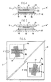
- the upper and lower rollers 17 and 18 are stacked in two rows forming an angle of 90°.
- the material of the upper and lower rollers 17 and 18 may be anything that can withstand vertical loads, for example, metal, concrete, ceramics, rigid plastics, or FRP.
- the numeral 19 denotes an intermediate pressure resisting plate in the form of a steel plate or the like interposed between the upper and lower rollers 17 and 18, with elastomeric bodies 20 and 21 in the form of sheets bonded to the upper and lower surfaces thereof as by vulcanization adhesion.
- the vibration-proofing device A wherein the intermediate pressure resisting plate 19 having elastomeric bodies 20 and 21 in the form of sheets bonded to the upper and lower surfaces thereof is interposed between the upper and lower rollers 17 and 18.
- the invention is not limited thereto.
- an elastomeric body 22 in the form of a sheet alone may be interposed between the upper and lower rollers 17 and 18.
- an intermediate pressure resisting plate-having no elastomeric bodies applied thereto may be interposed or, as shown in Fig. 5, the upper rollers 17 may be placed directly on the lower rollers 18.
- the vibration-proofing device B of this second embodiment like the vibration-proofing device A of the first embodiment, upon occurrence of an earthquake, not only horizontal but also vertical vibrations are reliably absorbed to reduce the input acceleration to the upper structure to protect the upper structure 11 from earthquakes.
- the angle formed between the upper and lower rollers 17 and 18 must be set accurately at 90°, as described with reference to Fig. 6.
- the first and second intermediate pressure resisting plates 19a and 19b having elastomeric bodies 20a, 21a, 20b and 21b bonded thereto have been used. However, they are not absolutely necessary; as in the case of the vibration-proofing devices A′ and A ⁇ in Figs. 4 and 5, elastomeric bodies alone with no intermediate pressure resisting plates combined therewith may be interposed or intermediate pressure resisting plates with no elastomeric bodies bonded thereto may be interposed or the rollers 17, 23 and 18 may be directly stacked using neither intermediate pressure resisting plates nor elastomeric bodies.
- the vertical component of a weak vibration such as a traffic vibration or a vibration from the equipment installed in another room, is absorbed by the elastic deformation of the elastomeric bodies 14, 16, 20 and 21 forming the rolling surfaces for the upper and lower rollers 17 and 18, while the vertical component of a strong vibration, such as an earthquake, is absorbed by the air spring 28.
- the horizontal components of a weak vibration, such as a traffic vibration, and of a strong vibration, such as an earthquake are absorbed in that the upper and lower rollers 17 and 18 roll on the rolling surfaces defined by the elastomeric bodies 14, 16, 20 and 21.
- the elastomeric bodies 14, 16, 20 and 21 elastically deform to thereby exert the damping performance In this manner, three-dimensional vibrations of vertical and horizontal directions of the lower structure due to traffic vibrations or earthquakes are blocked to maintain the upper structure stationary.
- the vibration-proofing device D of this fourth embodiment shown in Fig. 17 has coil spring means 32 disposed above the upper and lower rollers 17 and 18. Stated concretely, a plurality of vertical springs 33 are installed between the lower surface of the upper structure 11 and the upper pressure resisting plate 13. A pair of links 35 each comprising two levers 34 are installed between the end edges of the upper structure 11 and the upper pressure resisting plate 13, and a horizontal coil spring 37 is taut between the pivots 36 of the levers 34 of the links 35. In the figure, only one horizontal coil spring 37 is shown, but two or more horizontal coil springs may be provided. Further, it is not absolutely necessary to use both the vertical coil springs 33 and the horizontal coil spring 37 simultaneously; either of them alone may be used.
- an inverted conical pressure resisting plate 39 and a conical pressure resisting plate 40 Disposed on the lower surface of the upper structure 11 and the upper surface of the upper pressure resisting plate 13 are an inverted conical pressure resisting plate 39 and a conical pressure resisting plate 40, respectively, the lower and upper surfaces thereof having elastomeric bodies 41 and 42 bounded thereto as by vulcanization to form rolling surfaces for the rollers 38.
- the rollers 38 are rotatably held in radial arrangement by concentric large and small annular connector plates 43 and 44.
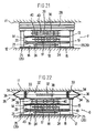
- the vibration-proofing device F of the sixth embodiment shown in Fig. 21 has an air spring disposed above the rollers 38 of the fifth embodiment, while the vibration-proofing device G of the seventh embodiment shown in Fig. 22 has coil spring means 32, instead of an air spring 28, disposed above the rollers 38 of the fifth embodiment.
- the air spring 28 and the coil spring means 32 in the vibration-proofing devices F and G of the sixth and seventh embodiments are the same as those used in the third embodiment shown in Fig. 13 and the fourth embodiment shown in Fig. 17 and a detailed description thereof is omitted.
- the vibration-proofing devices F and G of the sixth and seventh embodiments shown in Figs. 21 and 22 exert superior vibration-proofing function, absorbing all vibrations having horizontal, vertical and rotational components, including weak vibrations, such as traffic vibrations, and strong vibrations, such as earthquakes.
Landscapes
- Engineering & Computer Science (AREA)
- Architecture (AREA)
- Business, Economics & Management (AREA)
- Emergency Management (AREA)
- Environmental & Geological Engineering (AREA)
- Structural Engineering (AREA)
- Civil Engineering (AREA)
- Physics & Mathematics (AREA)
- General Engineering & Computer Science (AREA)
- Electromagnetism (AREA)
- Acoustics & Sound (AREA)
- Aviation & Aerospace Engineering (AREA)
- Mechanical Engineering (AREA)
- Vibration Prevention Devices (AREA)
Claims (7)
- Antivibrationsvorrichtung, die Rollen (17, 18) aufweist, die zwischen der oberen und der unteren Konstruktion (11, 12) für das horizontale Tragen der oberen Konstruktion (11) angeordnet sind; dadurch gekennzeichnet, daß vertikal einen Abstand aufweisenden oberen und unteren elastomeren Körper (14, 16) vorhanden sind, jeder in der Form einer Platte, die entsprechend durch die untere Fläche der oberen Konstruktion (11) und die obere Fläche der unteren Konstruktion (12) getragen werden, so daß gegenüberliegende Rollflächen gebildet werden: und daß die Rollen (17, 18) Zylinderrollen aus einem steifen Material sind, die nur vertikale Belastungen aushalten können, und die zwischen den oberen und den unteren elastomeren Körpern (14, 16) angeordnet sind, damit sie über die Rollflächen rollen können.
- Antivibrationsvorrichtung nach Anspruch 1, dadurch gekennzeichnet, daß die Zylinderrollen in n vertikal einen Abstand aufweisenden Reihen aufgeschichtet sind; die Rollen in jeder Reihe parallel sind; die parallelen Längsachsen der Zylinderrollen einer jeden Reihe einen Winkel von 180°/n mit den parallelen Längsachsen der Zylinderrollen der oder einer jeden anderen Reihe bilden; und ein elastomerer Körper (20,21), der die Rollflächen bereitstellt, zwischen dem oder jedem Paar der benachbarten Reihen der Zylinderrollen angeordnet ist.
- Antivibrationsvorrichtung nach Anspruch 2, bei der die Rollen in einer Schicht eine oder mehrere Rollen aufweisen, deren Achsen um bis zu 45° nicht parallel sind.
- Antivibrationsvorrichtung nach Anspruch 2, bei der die Rollen in einer Schicht eine oder mehrere Rollen aufweisen, deren Achsen um bis zu 30° nicht parallel sind.
- Antivibrationsvorrichtung nach Anspruch 2, bei der die Räume zwischen den benachbarten Rollen einer jeden Reihe variieren.
- Antivibrationsvorrichtung nach einem der Ansprüche 1 bis 5, dadurch gekennzeichnet, daß eine Luftfedervorrichtung (28) oder eine Spiralfedervorrichtung (32) zusätzlich zwischen der oberen und der unteren Konstruktion (11, 12) angeordnet ist.
- Antivibrationsvorrichtung nach einem der Ansprüche 1 bis 6, dadurch gekennzeichnet, daß eine Vielzahl von Kegelrollen (38) radial in einer horizontalen Ebene über den Zylinderrollen (17, 18) angeordnet ist.
Applications Claiming Priority (6)
| Application Number | Priority Date | Filing Date | Title |
|---|---|---|---|
| JP2010910A JP2927357B2 (ja) | 1990-01-20 | 1990-01-20 | 免震支持装置 |
| JP10910/90 | 1990-01-20 | ||
| JP257873/90 | 1990-09-26 | ||
| JP257874/90 | 1990-09-26 | ||
| JP25787390A JPH04136543A (ja) | 1990-09-26 | 1990-09-26 | 防振装置 |
| JP2257874A JP2933091B2 (ja) | 1990-09-26 | 1990-09-26 | 防振装置 |
Publications (3)
| Publication Number | Publication Date |
|---|---|
| EP0439272A2 EP0439272A2 (de) | 1991-07-31 |
| EP0439272A3 EP0439272A3 (en) | 1992-01-02 |
| EP0439272B1 true EP0439272B1 (de) | 1996-05-29 |
Family
ID=27279159
Family Applications (1)
| Application Number | Title | Priority Date | Filing Date |
|---|---|---|---|
| EP91300313A Expired - Lifetime EP0439272B1 (de) | 1990-01-20 | 1991-01-16 | Antivibrationsvorrichtung |
Country Status (3)
| Country | Link |
|---|---|
| EP (1) | EP0439272B1 (de) |
| DE (1) | DE69119797D1 (de) |
| NZ (1) | NZ236812A (de) |
Cited By (2)
| Publication number | Priority date | Publication date | Assignee | Title |
|---|---|---|---|---|
| WO2004079113A1 (en) * | 2003-03-07 | 2004-09-16 | Robinson Seismic Limited | A self-centring sliding bearing |
| CN108360702A (zh) * | 2018-01-18 | 2018-08-03 | 同济大学 | 利用金属片屈服消能的减振器 |
Families Citing this family (18)
| Publication number | Priority date | Publication date | Assignee | Title |
|---|---|---|---|---|
| US5327692A (en) * | 1991-08-01 | 1994-07-12 | Kajima Corporation | Vertical vibration control device |
| JP3194542B2 (ja) * | 1992-08-04 | 2001-07-30 | 住友ゴム工業株式会社 | 振動減衰装置 |
| GR1001450B (el) * | 1992-12-24 | 1993-12-30 | Ioannis Logiadis | Αντισεισμικός σύνδεσμος δεσμευμένης ταλάντωσης για μία ασφαλή σεισμική μόνωση των κατασκευών. |
| NL9400302A (nl) * | 1994-02-28 | 1995-10-02 | Parora Wilhelmus Adrianus Van | Inrichting voor het beschermen van bouwwerken, constructies en dergelijke tegen aardbevingen. |
| CN1065599C (zh) * | 1996-05-11 | 2001-05-09 | 北方设计研究院 | 一种减振器及一种带水平阻尼装置的减振器 |
| KR100384591B1 (ko) | 1997-08-08 | 2003-05-22 | 로빈슨 사이즈믹 리미티드 | 에너지 흡수기 |
| US6364274B1 (en) * | 1999-11-18 | 2002-04-02 | Mitsubishi Steel Mfg. Co., Ltd. | Seismic isolator for exhibits |
| WO2001042593A2 (en) * | 1999-12-01 | 2001-06-14 | The Research Foundation Of The State University Of New York At Buffalo | Seismic isolation bearing |
| US6971795B2 (en) | 2001-11-26 | 2005-12-06 | Lee George C | Seismic isolation bearing |
| CN103114650B (zh) * | 2013-02-17 | 2015-05-13 | 王涛 | 辊轴式金属隔震支座 |
| CN103993676A (zh) * | 2014-04-12 | 2014-08-20 | 北京工业大学 | 十字形角钢装配式钢结构自复位防屈曲支撑 |
| CN106245780B (zh) * | 2016-09-23 | 2018-06-29 | 沈阳建筑大学 | 有限位移缓冲滑动支座结构及组装方法 |
| CN106948507A (zh) * | 2017-03-24 | 2017-07-14 | 辽宁工程技术大学 | 一种可扭转的限位隔震装置 |
| CN107605061B (zh) * | 2017-09-04 | 2023-05-05 | 丰泽智能装备股份有限公司 | 斜面导向式减隔震自复位支座 |
| EP3604713B1 (de) * | 2018-08-03 | 2021-02-24 | Institute for Plasma Research | Verschiebungsentkopplungsanordnung für rohrleitungssysteme |
| CN112813741B (zh) * | 2021-02-03 | 2024-12-13 | 广州大学 | 轨道交通用三维隔振装置 |
| CN116556434A (zh) * | 2023-01-18 | 2023-08-08 | 中铁十五局集团有限公司 | 一种用于地下结构支撑柱的多维度减震耗能滚动支座 |
| CN119507572B (zh) * | 2025-01-14 | 2025-04-08 | 山西省建筑科学研究院检测中心有限公司 | 一种建筑隔震橡胶支座 |
Family Cites Families (7)
| Publication number | Priority date | Publication date | Assignee | Title |
|---|---|---|---|---|
| US1761659A (en) * | 1928-01-18 | 1930-06-03 | Frank D Cummings | Building construction |
| DE1160873B (de) * | 1961-06-13 | 1964-01-09 | Wolfhart Andrae Dipl Ing | Kipplager fuer Bruecken und aehnliche Bauwerke |
| DE1290321B (de) * | 1966-03-08 | 1969-03-06 | Gumba Gummi Im Bauwesen Gmbh | Rollenlager |
| US3762114A (en) * | 1972-07-19 | 1973-10-02 | L Eskijian | Earthquake resistant system |
| US4517778A (en) * | 1981-10-15 | 1985-05-21 | Nicolai Charles M | Earthquake-proof building with improved foundation |
| DE3408591A1 (de) * | 1983-05-18 | 1985-10-24 | Eckart Markus | Isolierungs-daempfungskoerper fuer wandartige stahlbetontragwerke |
| JPS63223244A (ja) * | 1987-03-12 | 1988-09-16 | 鹿島建設株式会社 | 防振、免震装置 |
-
1991
- 1991-01-16 EP EP91300313A patent/EP0439272B1/de not_active Expired - Lifetime
- 1991-01-16 DE DE69119797T patent/DE69119797D1/de not_active Expired - Lifetime
- 1991-01-18 NZ NZ236812A patent/NZ236812A/en unknown
Cited By (4)
| Publication number | Priority date | Publication date | Assignee | Title |
|---|---|---|---|---|
| WO2004079113A1 (en) * | 2003-03-07 | 2004-09-16 | Robinson Seismic Limited | A self-centring sliding bearing |
| CN100416005C (zh) * | 2003-03-07 | 2008-09-03 | 鲁宾逊地震Ip有限公司 | 轴承组件 |
| CN108360702A (zh) * | 2018-01-18 | 2018-08-03 | 同济大学 | 利用金属片屈服消能的减振器 |
| CN108360702B (zh) * | 2018-01-18 | 2019-10-01 | 同济大学 | 利用金属片屈服消能的减振器 |
Also Published As
| Publication number | Publication date |
|---|---|
| EP0439272A2 (de) | 1991-07-31 |
| NZ236812A (en) | 1998-04-27 |
| DE69119797D1 (de) | 1996-07-04 |
| EP0439272A3 (en) | 1992-01-02 |
Similar Documents
| Publication | Publication Date | Title |
|---|---|---|
| US5261200A (en) | Vibration-proofing device | |
| EP0439272A2 (de) | Antivibrationsvorrichtung | |
| US20040221520A1 (en) | All-directional damping and earthquake-resisting unit | |
| US10948043B2 (en) | Damping device for structure | |
| US5161338A (en) | Laminated rubber support assembly | |
| KR20060075358A (ko) | 저 마찰 구름운동 진자받침 | |
| JP4138534B2 (ja) | 免震構造物の半固定装置 | |
| JPH09144810A (ja) | 構造物用3次元免震装置 | |
| JP3804406B2 (ja) | 減衰力調整機能付皿ばねユニット | |
| JPH04343982A (ja) | 動吸振装置 | |
| JP2927357B2 (ja) | 免震支持装置 | |
| JP4439694B2 (ja) | 高層建物の高減衰架構 | |
| JPH09184542A (ja) | 免震装置 | |
| JP2001082542A (ja) | 三次元免震装置 | |
| JP2002174292A (ja) | 摩擦ダンパー | |
| JP3753264B2 (ja) | 建物の免震装置 | |
| JPH04136543A (ja) | 防振装置 | |
| JPH03272343A (ja) | 二重型マスダンパー | |
| JP3663563B2 (ja) | 免震装置 | |
| JP7833308B2 (ja) | ダンパー装置 | |
| JP7350964B1 (ja) | 免震装置 | |
| JP2002181124A (ja) | 摩擦ダンパー | |
| JP2907310B2 (ja) | 免振装置 | |
| JPH0520807Y2 (de) | ||
| CA3019700A1 (en) | Damping device for structure |
Legal Events
| Date | Code | Title | Description |
|---|---|---|---|
| PUAI | Public reference made under article 153(3) epc to a published international application that has entered the european phase |
Free format text: ORIGINAL CODE: 0009012 |
|
| AK | Designated contracting states |
Kind code of ref document: A2 Designated state(s): DE FR GB IT |
|
| PUAL | Search report despatched |
Free format text: ORIGINAL CODE: 0009013 |
|
| AK | Designated contracting states |
Kind code of ref document: A3 Designated state(s): DE FR GB IT |
|
| 17P | Request for examination filed |
Effective date: 19920130 |
|
| 17Q | First examination report despatched |
Effective date: 19930222 |
|
| GRAA | (expected) grant |
Free format text: ORIGINAL CODE: 0009210 |
|
| AK | Designated contracting states |
Kind code of ref document: B1 Designated state(s): DE FR GB IT |
|
| ITF | It: translation for a ep patent filed | ||
| REF | Corresponds to: |
Ref document number: 69119797 Country of ref document: DE Date of ref document: 19960704 |
|
| ET | Fr: translation filed | ||
| PG25 | Lapsed in a contracting state [announced via postgrant information from national office to epo] |
Ref country code: DE Effective date: 19960830 |
|
| PLBE | No opposition filed within time limit |
Free format text: ORIGINAL CODE: 0009261 |
|
| STAA | Information on the status of an ep patent application or granted ep patent |
Free format text: STATUS: NO OPPOSITION FILED WITHIN TIME LIMIT |
|
| 26N | No opposition filed | ||
| REG | Reference to a national code |
Ref country code: GB Ref legal event code: IF02 |
|
| PGFP | Annual fee paid to national office [announced via postgrant information from national office to epo] |
Ref country code: FR Payment date: 20020110 Year of fee payment: 12 |
|
| PGFP | Annual fee paid to national office [announced via postgrant information from national office to epo] |
Ref country code: GB Payment date: 20020116 Year of fee payment: 12 |
|
| PG25 | Lapsed in a contracting state [announced via postgrant information from national office to epo] |
Ref country code: GB Free format text: LAPSE BECAUSE OF NON-PAYMENT OF DUE FEES Effective date: 20030116 |
|
| GBPC | Gb: european patent ceased through non-payment of renewal fee | ||
| PG25 | Lapsed in a contracting state [announced via postgrant information from national office to epo] |
Ref country code: FR Free format text: LAPSE BECAUSE OF NON-PAYMENT OF DUE FEES Effective date: 20030930 |
|
| REG | Reference to a national code |
Ref country code: FR Ref legal event code: ST |
|
| PG25 | Lapsed in a contracting state [announced via postgrant information from national office to epo] |
Ref country code: IT Free format text: LAPSE BECAUSE OF NON-PAYMENT OF DUE FEES;WARNING: LAPSES OF ITALIAN PATENTS WITH EFFECTIVE DATE BEFORE 2007 MAY HAVE OCCURRED AT ANY TIME BEFORE 2007. THE CORRECT EFFECTIVE DATE MAY BE DIFFERENT FROM THE ONE RECORDED. Effective date: 20050116 |