EP0439309A2 - Gerät zur Wiedergabe und Verstärkung von Schallsignalen - Google Patents
Gerät zur Wiedergabe und Verstärkung von Schallsignalen Download PDFInfo
- Publication number
- EP0439309A2 EP0439309A2 EP91300433A EP91300433A EP0439309A2 EP 0439309 A2 EP0439309 A2 EP 0439309A2 EP 91300433 A EP91300433 A EP 91300433A EP 91300433 A EP91300433 A EP 91300433A EP 0439309 A2 EP0439309 A2 EP 0439309A2
- Authority
- EP
- European Patent Office
- Prior art keywords
- sound
- signal
- reproducing
- vocal sound
- casing
- Prior art date
- Legal status (The legal status is an assumption and is not a legal conclusion. Google has not performed a legal analysis and makes no representation as to the accuracy of the status listed.)
- Withdrawn
Links
Images










Classifications
-
- H—ELECTRICITY
- H04—ELECTRIC COMMUNICATION TECHNIQUE
- H04R—LOUDSPEAKERS, MICROPHONES, GRAMOPHONE PICK-UPS OR LIKE ACOUSTIC ELECTROMECHANICAL TRANSDUCERS; ELECTRIC HEARING AIDS; PUBLIC ADDRESS SYSTEMS
- H04R27/00—Public address systems
-
- G—PHYSICS
- G11—INFORMATION STORAGE
- G11B—INFORMATION STORAGE BASED ON RELATIVE MOVEMENT BETWEEN RECORD CARRIER AND TRANSDUCER
- G11B25/00—Apparatus characterised by the shape of record carrier employed but not specific to the method of recording or reproducing, e.g. dictating apparatus; Combinations of such apparatus
- G11B25/06—Apparatus characterised by the shape of record carrier employed but not specific to the method of recording or reproducing, e.g. dictating apparatus; Combinations of such apparatus using web-form record carriers, e.g. tape
- G11B25/063—Apparatus characterised by the shape of record carrier employed but not specific to the method of recording or reproducing, e.g. dictating apparatus; Combinations of such apparatus using web-form record carriers, e.g. tape using tape inside container
-
- G—PHYSICS
- G11—INFORMATION STORAGE
- G11B—INFORMATION STORAGE BASED ON RELATIVE MOVEMENT BETWEEN RECORD CARRIER AND TRANSDUCER
- G11B31/00—Arrangements for the associated working of recording or reproducing apparatus with related apparatus
-
- G—PHYSICS
- G11—INFORMATION STORAGE
- G11B—INFORMATION STORAGE BASED ON RELATIVE MOVEMENT BETWEEN RECORD CARRIER AND TRANSDUCER
- G11B33/00—Constructional parts, details or accessories not provided for in the other groups of this subclass
- G11B33/02—Cabinets; Cases; Stands; Disposition of apparatus therein or thereon
- G11B33/022—Cases
- G11B33/025—Portable cases
-
- H—ELECTRICITY
- H04—ELECTRIC COMMUNICATION TECHNIQUE
- H04R—LOUDSPEAKERS, MICROPHONES, GRAMOPHONE PICK-UPS OR LIKE ACOUSTIC ELECTROMECHANICAL TRANSDUCERS; ELECTRIC HEARING AIDS; PUBLIC ADDRESS SYSTEMS
- H04R1/00—Details of transducers, loudspeakers or microphones
- H04R1/08—Mouthpieces; Microphones; Attachments therefor
Definitions
- the present invention relates to an apparatus for reproducing and amplifying sound.
- the invention is not so restricted, it relates more particularly to an apparatus adapted to be used for a "kara-oke” (literally “empty orchestra") performance in which a singer is accompanied by a taped recording.
- the latter is normally of an orchestra in which there is no singer and which is therefore "empty”.
- apparatus for reproducing and amplifying sound comprising a vocal sound input device for inputting the sound of the voice of the user of the apparatus; recorded instrumental sound reproducing means; and mixing and amplifying means for mixing and amplifying signals from the vocal sound input device and from the recorded instrumental sound reproducing means characterised in that the mixing and amplifying means is also arranged to receive signals from a recorded vocal sound reproducing means, adjustment means being provided for adjusting the relative intensity of signals which are transmitted to the mixing and amplifying means from the vocal sound input device and from the recorded vocal sound reproducing means.
- the apparatus is a portable apparatus comprising casing means provided with a speaker and with the recorded instrumental sound reproducing means, the recorded vocal sound reproducing means, the mixing and amplifying means and the adjustment means; the casing means being provided with the vocal sound input device at a position substantially spaced from said speaker.
- the casing means has a manually grippable portion by means of which the apparatus is handled, the casing means being of elongated shape and the manually grippable portion extending longitudinally thereof, the vocal sound input device and the speaker being disposed adjacent opposite ends of the casing means.
- the adjustment means may comprise a switch which is operable to prevent the input to the mixing and amplifying means of signals from the recorded vocal sound reproducing means.
- the adjustment means may also comprise a variable resistor for varying the relative intensity of signals inputted into the mixing and amplifying means from the recorded vocal sound reproducing means and from the recorded instrumental sound reproducing means.
- the apparatus may be adapted for use with a recording containing a plurality of musical items with gaps therebetween; the apparatus comprising a drive motor for driving the said recording; a starting signal generating means for producing a starting signal to start a scanning of the recording; and a detecting circuit, operative upon receiving a said starting signal, to detect in the course of said scanning a non-signal or a low level condition of the output from the recorded instrumental and vocal sound reproducing means and thus to produce a detection signal indicating a gap in the recording, there being motor stopping means for stopping the supply of power to the drive motor in response to a said detection signal.
- drive control means which, when in an operative state, ensures that the motor, when the latter is also operative, drives the recording at a fast forward or a fast rearward speed, the motor stopping means stopping the drive motor in response to a said detection signal at a time when the drive control means is held in its operative state.
- apparatus for reproducing and amplifying sound comprising recorded sound reproducing means for reproducing sound from a recording containing a plurality of items with gaps therebetween; a drive motor for driving a said recording through the recorded sound reproducing means; a starting signal generating means for producing a starting signal to start a scanning of the recording; and a detecting circuit, operative upon receiving a said starting signal, to detect in the course of said scanning a non-signal or a low level condition of the output from the recorded sound reproducing means and thus to produce a detection signal indicating a gap in the recording characterised by motor stopping means for stopping the supply of power to the drive motor in response to a said detection signal.
- the apparatus of the present invention may be used by a singer to provide a "kara-oke” performance while holding the apparatus in one hand.
- the apparatus provides a compact, miniature and lightweight "kara-oke” music set which reproduces and amplifies audio-sound from an audio-recording medium, and which simultaneously amplifies singing sound from the user.
- the apparatus may comprise a circuit system having an instant pop-up function for reproducing a vocal sound using a sound multiplex recording medium, and a circuit system and a mechanism having a music tune selecting function and an automatic tune heading setting function.
- the apparatus of the present invention may be constituted by a portable audio reproducing and amplifying apparatus which enables the so-called "kara-oke” set to be held by one hand, and also to be miniature and lightweight, the apparatus having an auxiliary voice function such that vocal sounds by a professional singer or the like can be reproduced through an incorporated speaker if the user forgets the words of a song being sung.
- a music reproducing signal and a vocal reproducing signal are amplified by and issued from the speaker through the mixing and amplifying means, and there are provided further, a signal intensity changing means for changing at least the intensity of a vocal sound reproducing signal fed to the mixing and amplifying means by external manipulation of a volume knob or the like, and a signal intensity setting means for forcibly setting the intensity of a vocal sound reproducing signal fed to the mixing and amplifying means to a predetermined value after disabling the signal intensity changing means at the time of external manual operation of a push button or the like.
- a vocal sound which cannot be normally perceived can be instantly heard due to adjustment to the signal intensity changing means, by operating the signal intensity setting means so as to set the intensity of a vocal sound reproducing signal to a certain value.
- the present invention also relates to a device for automatically stopping a drive motor for a reproducing device upon completion of setting a heading of a tune. That is, there may be provided an inter tune gap detecting circuit, an initiation signal generating means for generating a signal for initiating a tune "intro-scan" operation at the time of a manual operation of a high speed forward feed or high speed rearward feed during a reproducing mode, and a motor stopping circuit for stopping the supply of power to the drive motor for the vocal sound reproducing device in association with a detection signal from the inter tune gap detecting circuit.
- the drive motor may be electrically stopped without forcibly releasing the locking condition of a high speed forward or rearward feed mechanism. Accordingly, battery power can be saved due to a reduction in the consumption of current.
- a "kara-oke” system (or set) has comprised, in general, a reproducing device for reproducing a tune (instrumental) recorded on a vocal sound recording medium such as a magnetic tape, an optical disc or the like; a microphone for inputting vocal sound from a singer; a mixing and amplifying device for combining a tune signal from the reproducing device with a vocal sound signal from the microphone and amplifying the thus combined signal; and a speaker for converting the thus amplified signal into sound waves.
- the reproducing device and the mixing and amplifying device are sometimes integrally incorporated with each other (being disposed in a single unit housing), the microphone for picking up external sound and the speaker as a sound amplifying means are constituted as separate independent devices, respectively.
- the reproducing device can select several tunes successively, and can reproduce them with a high quality, and it is desirable that the microphone is a miniature and lightweight wireless portable microphone which can smoothly follow a singing pose of a person. Accordingly, it is necessary that these devices are formed as separate structures, respectively having the necessary functions.
- a conventional "kara-oke” music system requires a very large installation space as a whole, and in many cases cannot be easily moved. That is, the conventional "kara-oke” music system has a very large size and a very great weight of many Kg. Consequently, an adult person can move it only with difficulty. Accordingly, it is difficult to make the system portable since it is mainly in general of a stationary type. Even though the "kara-oke” music system can be moved to a new installation place, connection between electrical cords or the like and adjustments are inevitable.
- any attempt to make a "kara-oke” music system portable encounters many design difficulties, and it is indispensable to make the reproducing device, the microphone and the speaker miniature and lightweight and to integrate them in one unit.
- the apparatus must also have a "kara-oke” music function which can amplify vocal sound from a singer and reproduce the sound of a tune, simultaneously.
- the positional relationship between the microphone and the speaker, the distance therebetween, the directivity and the like should be taken into consideration in order to reduce as much as possible a howling phenomenon caused by a feed-back of amplified sound from the speaker to the microphone.
- a hand book of songs is not always available, and accordingly there is liable to be an interruption in the singing of a song since a singer may forget a part of the lines of the song during singing. Accordingly, a person who has no confidence in himself of remembering the lines of a song tends to hesitate to perform. Therefore, with a "kara-oke” music set having no singing assisting means, "kara-oke” music cannot be adequately performed. Accordingly, the invention enables a "kara-oke” music set to have a vocal sound assisting function, instead of a handbook of songs.
- the speaker is stored in a casing body at one of, for example, an upper position and a lower position thereof, and the main parts of the vocal sound reproducing device are disposed in the casing body at the other position, such as a position which is on the upper side, the lower side, one of both sides or the rear side of the speaker, or in a casing integrally incorporated with the casing body.
- the gripping section is composed of at least one or two parts which are coupled and integrally incorporated with the casing body, or the casing.
- the vocal sound input section is coupled to the gripping section, the casing body or the casing integrally therewith. In such a positional arrangement, the vocal sound input section is arranged at a position which is sufficiently spaced from the speaker to prevent howling.
- the vocal sound reproducing device may be constituted as a sound multiplex reproducing apparatus comprising a vocal sound reproducing circuit and a tune reproducing circuit having a singing accompaniment function, and may further comprise a mixing and amplifying means, a signal intensity changing means and a signal intensity setting means.
- the mixing and amplifying means may mix a vocal sound reproduction signal from the vocal sound reproducing circuit and a tune reproduction signal from the tune reproducing circuit, and may amplify the same.
- the signal intensity changing means may change at least the intensity of a vocal sound reproduction signal fed to the mixing and amplifying means in association with an external manual operation.
- the signal intensity setting means may disable the signal intensity changing means in association with an external manual operation,and may then set the intensity of a vocal sound reproduction signal fed to the mixing and amplifying means forcibly to a predetermined value.
- the signal intensity changing means may adjust the intensity of the vocal sound reproduction signal so as to set a balance between a vocal sound volume and a tune sound volume.
- a loud sound which is obtained by amplifying the singing sound, a vocal sound (a vocal by, for example, a professional singer) and a tune sound may be mixed and may be put out from the speaker. If the vocal sound volume is decreased by adjusting the signal intensity changing means, the so-called “kara-oke" music performance in which the vocal sound, the loud sound and the tune sound are mixed together is realized.
- the signal intensity setting means when the signal intensity setting means is energized through an external manual operation, the signal intensity adjusting means for adjusting the intensity of a vocal sound reproduction signal is disabled, and then the intensity of the vocal sound reproduction signal is reset to a predetermined value, and accordingly, a vocal sound is also put out from the speaker. Therefore, the singer can continue his singing while copying the vocal sound.
- the signal intensity changing means is composed of, for example, a first signal intensity attenuating means for variably attenuating the intensity of a vocal sound reproduction signal, and a second signal intensity attenuating means for attenuating a tune signal reproduction signal fed to the mixing and amplifying means.
- the amplification factors of signals fed to the mixing and amplifying means may be changed respectively, but first and second signal intensity attenuating means are preferably used since their arrangements are simple.
- the first and second attenuating means may be arranged separately from each other, but with the purpose of reducing the number of components it is preferably constituted by a single variable resistor.
- the signal intensity setting means may be composed of a switch means for cutting off signal attenuation made by the first signal attenuating means.
- the switch means is connected in series to a slider of the single variable resistor which is the signal intensity changing means. If this switch means is of a push button type, the manually operable part of the push button is desirably positioned on the gripping section or in an area in the vicinity of the grip section, in which a thumb of the user can manipulate the push button, since this improves operability.
- an initiation signal generating means for generating a signal for initating a tune "intro-scan” operation at the time of a high speed forward feed operation or a high speed rearward feed operation during reproduction mode
- an inter tune gap detecting circuit for detecting a non-signal condition or a low level condition of a reproduction signal from the vocal sound reproducing device in association with the delivered operation initiation signal
- a motor stopping circuit for stopping the supply of power to a drive motor for the vocal sound reproducing device in accordance with a detection signal from the inter tune gap detecting circuit.
- a lock condition of a mechanism for the high speed forward feed operation and high speed rearward feed operation has been forcibly released by a solenoid plunger or the like when an inter tune gap detection signal is delivered.
- the incorporated motor stopping circuit cuts off the supply of power to the drive motor so as to electrically and directly stop the same. Accordingly, no substantial current is consumed for stopping the motor upon the stopping of a tune scanning operation, and accordingly, it is possible to save the power of an incorporated power source.
- a detection complete sound generating circuit for issuing an alarm sound or an artificial voice from the above-mentioned speaker in accordance with a detection signal from the inter tune gap detecting circuit.
- the initiation signal generating means may be composed of, for example, an AND circuit consisting of a first switch means opened and closed in association with a high speed forward feed operation and a second switch means opened and closed in association with a high speed rearward feed operation, these switches being of a leaf type.
- a pushing member for each leaf type switch there may be provided a projection formed on the rear side of a push button switch for each mode selecting lever.
- the drive motor may be automatically stopped after completion of a tune scanning operation, the high speed forward feed or high speed rearward feed operation mechanism system is held in its locked condition, but the initiation signal generating means is in its active condition. Accordingly, there is provided a means for stopping the continuation of generation of the initiation signal for initiating a tune scanning operation.
- a start lever for releasing the locked conditions of a high speed forward feed operation selecting lever,and returning them into only a reproducing mode.
- a push button may project from a casing body fitted on an engagement member of the start lever, which is for restarting the reproducing mode by one step motion to the push button.
- the signal intensity changing means may adjust the intensity of a vocal sound reproduction signal, and as a result, the balance between a vocal sound volume and a tune sound volume may be set.
- a voice from a singer is introduced into the vocal sound input section, an amplified singing sound and the vocal sound (vocal by, for example, a professional singer) and a tune sound are mixed and issued from the speaker.
- the vocal sound volume is decreased by adjusting the signal intensity changing means, the so-called "kara-oke" music operation in which the amplified singing sound and the tune sound (instrumental) are mixed together, can be achieved.
- the signal intensity setting means when the signal intensity setting means is energized through external manipulation, the signal intensity changing means for adjusting the intensity of a vocal reproduction signal is disabled, and accordingly, the intensity of the vocal sound reproduction signal is reset to a predetermined value, so that the recorded vocal sound is also issued from the speaker. Thereby, the singer can continue his singing while copying the recorded vocal sound.
- the motor stopping circuit is used for stopping the supply of power to the drive motor for the vocal sound reproducing device in association with a detection signal from the inter tune gap detecting circuit, when an inter tune gap detection signal is issued, the locked condition of the mechanism for the high speed forward feed operation or the high speed rearward feed operation is not released forcibly by a solenoid plunger or the like, but the internal motor stopping circuit directly stops the drive motor while the above-mentioned mechanism is held in its locked condition as it is. Accordingly, upon completion of a tune scanning operation, no excessively large current is consumed for driving the mechanism, and accordingly, it is possible to save the power of the incorporated power source or the like.
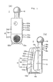
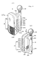
- a portable apparatus 1 for reproducing and amplifying sound according to a first embodiment of the present invention is constituted by a compact arrangement having certain predetermined maximum external dimensions, that is, an overall height of 283 mm including projections, a width of 97 mm and a depth of 128 mm, and a weight of 640g including a dry battery.
- the apparatus 1 is roughly composed of an apparatus body section or casing body 12, a gripping portion 14 and a microphone section 16.
- the apparatus body section 12 is composed of a vocal sound medium storage section 120 for a tape cassette stored in a substantially rectangular parallelopiped body casing 12a and a speaker storage section 130 which is positioned below the vocal sound medium storage section 120. It is to be noted that a tape deck or the like for reproducing vocal sound, which will be described later, is stored on the rear side of the vocal sound medium storage section 120.
- the push button member 120a is for stopping the feed of a magnetic tape
- the push button member 120b for fast-feeding the magnetic tape
- the push button member 120c for rewinding the magnetic tape
- the push button member 120d for playing the reproduction of a vocal sound signal recorded on the magnetic tape.
- the volume knob 130a is for adjusting the echo of the microphone sound
- the volume knob 130b is for adjusting the balance between the microphone sound volume and the tape reproduced sound volume.
- the grip section 14 and the microphone section 16 which is integrally incorporated with the grip section 14 form a substantially cylindrical body, the microphone section 16 being positioned in this cylindrical body. Further, leg parts 132a, 132b project from the left and right sides of the bottom surface of the apparatus body 12.
- a manual operating section 18 is provided on the side surface of the cylindrical casing between the grip section 14 and the microphone section 16.
- the manual operating section 18 is provided thereon with a knob 18a for a slide switch, and with rotary volume controls 18b, 18c positioned above and below the knob 18a.
- the knob 18a is adapted to change over the operation mode between the mode in which the apparatus is used as a "kara-oke" ("empty orchestra") music set and the mode in which it is used only as a loudspeaker for making the sound inputted into the microphone louder.
- the volume control 18b is for adjusting the balance between the vocal sound volume and the musical performance sound volume when using a sound multiplex magnetic tape.
- the volume control 18c is for adjusting the volume of the microphone sound.
- the cylindrical grip section 14 is coupled integrally to the apparatus body section 12 by means of upper and lower coupling parts 10a, 10b. Between the grip section 14 and the apparatus body section 12, there is defined a through space 15 which enables the grip section 14 to be gripped relatively
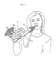
- the above-mentioned miniature and lightweight apparatus 1 is used in the way shown in Figure 2. That is, when used in the "kara-oke” or “empty orchestra” mode, the grip section 14 is held by one or both hands so as to carry the apparatus 1, and a song is sung into the microphone section 16, the singer being accompanied by the taped music of the "empty orchestra” so as to produce a quasi-professional effect. Since the apparatus is miniature and lightweight, the apparatus 1 can be carried suitably for a singing pose, similar to that employed when an ordinary wireless microphone is used.
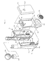
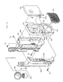
- FIG. 3 is an exploded perspective view illustrating the casing of the apparatus.
- the casing of the portable audio reproducing and sound volume increasing apparatus 1 is mainly composed of a plastics body casing 12a, a plastics right half 14a and a plastics left half 14b. Accordingly, the assembly thereof can be facilitated.
- the right and left halves 14a, 14b are assembled integrally together by means of a screw S1.
- the body casing 12a is assembled to the thus obtained assembly by means of screws S2, S3.
- the body casing 12a has an opening and closing cover 144 which is attached thereto and which can be opened and closed freely in the vertical direction through the intermediary of a plastics hinge 142. When the cover 144 is closed, a tape cassette storage chamber 146 is maintained in an air-tight condition.
- a speaker 132 ( Figure 4), which will be described below, is disposed in the speaker storage section 130 in the body casing 12a, the speaker 132 having its front surface covered thereover with a mesh-like speaker cover 134.
- a cap (microphone holder) 148 incorporated with an electret capacitor microphone 148a is inserted into the upper end part of the cylindrical body which is formed at the right and left halves 14a, 14b, and the cap 148 is covered with a sponge protector member 150.
- the push button members 120a, 120b, 120c, 120d, for the push button switches, and the knobs 130a, 130b project from the side surface of the body casing 12a.
- a miniature planar manual operating section composed of touch switches and the like can be used in the apparatus, the latter is more difficult to see and use. If the apparatus is used in the dark, such a miniature planar manual operating section is hardly visible.
- the use of push button members which project from the side surface of the casing to a certain extent is more suitable since they can be easily recognized due to the difference in dark and bright contrast.
- the push button members 120a, 120b, 120c, 120d and the knobs 130a, 130b have different colours so as to be highly distinguishable during use.
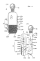
- FIG 4 is a side view showing the positional relationship between the speaker and the microphone section in the apparatus.
- the miniature speaker 132 has a relatively powerful magnet 132a which is located in the speaker storage section 130 and is positioned in the lower section of the apparatus body 12.
- the miniaturization of the speaker 132 is required for the portability of the apparatus.
- a powerful magnet 132a is important in order to reduce power consumption.
- the use of the powerful magnet 132a for a small size speaker 132 increases the total weight of the apparatus, so as to make it somewhat more difficult to hold in one hand and somewhat less portable, nevertheless the entire apparatus can be made lightweight by making the other components lightweight and by reducing the number of necessary components.
- the speaker storage section 130 is positioned in the lower part of the apparatus body section 12 and, further, that a relatively heavy magnet 132a is used is advantageous in the lowering of the centre of gravity of the elongated apparatus, and as mentioned later, this enables stationary stability and standing stability to be obtained.
- the cylindrical microphone section 16 includes the above-mentioned cap 148 which is provided in its top part with the capacitor microphone 148a.
- the direction of the pressure receiving area (directivity) of the microphone 148a is set along the axis of the microphone section 16. Accordingly, the centre axis of the directivity of the capacity microphone 148a and the centre axis of the directivity of the speaker 132 are orthogonal to each other.
- the position of the capacitor microphone 148a is in the uppermost part of the apparatus, the position of the speaker 132 being in the lowermost part of the apparatus, and the distance therebetween is about 24 cm. The reason why such a positional arrangement is adopted is to prevent howling. The longer the said distance, the greater is the degree of prevention of howling.
- the directivity of the capacitor microphone 148a is most preferably in the direction opposite (i.e. at an angle of 180 deg.) to the directivity of the speaker 132. Accordingly, the microphone section 16 may be fixed so as to be inclined rearwardly to, for example, the grip section 14, or the position of the capacitor microphone 142a itself may be changed.
- the relative positional relationship of the components required for a portable type miniature and lightweight "kara-oke" music set similar to the apparatus described above is such that the speaker section is fixed before the grip section and the microphone section, and the microphone section is desirably above the grip section while the speaker and the microphone section are spaced from each other by a distance which prevents the occurrence of severe howling.
- the microphone section may be positioned either before or behind the gripping section, but it should preferably not be arranged before the speaker section.
- the casing body serving as a speaker box, in which the speaker section is disposed, may also store the vocal sound reproducing device at another position. Alternatively, this vocal sound reproducing device may be disposed in a casing integrally incorporated with the casing body.
- the speaker section may be positioned before the storage section for the vocal sound reproducing device.
- the grip section is integrally incorporated with the storage section for the vocal sound reproducing device
- the microphone section is integrally incorporated at either the grip section or the upper or lower section of the vocal sound reproducing device.
- a microphone adapted for use in "kara-oke" is usually rod-like since it is preferably held by one hand in order to feel at ease.
- the inside of the coupling part 10a is hollow, which is therefore effectively used for the passage therethrough of the wiring from the microphone, and further, the inside of the coupling part 10b is also hollow since the wiring from the power source is led therethrough.
- an empty space in the inside of the grip section 14 is used as a battery storage section (which is not shown). Accordingly, the speaker sound is likely to be fed back to the microphone 148a through these coupling parts 10a, 10b, as indicated by the broken line arrow shown in Figure 4. Not only does the speaker sound propagate through a space in the casing but the speaker also causes secondary vibration of the casing itself. This vibration of the casing also reaches the microphone section 16, possibly causing the occurrence of howling.
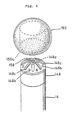
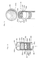
- a speaker sound feed-back preventing structure as shown in Figures 4 and 5 in order to prevent howling. That is, as shown in Figures 4 and 5(a), the cap 148 is fitted on a slightly reduced diameter end part 152a of a cylindrical casing 152, and the capacitor microphone 148a is attached to the top part of the cap 148.
- a perforated partition plate 154 is formed integrally in the cylindrical end part 152a. Under the partition wall 154 there are disposed a sound shield plate 155 in the form of a perforated metal disc (made of iron) and a lower sound absorbing member 156 made of relatively high density foamed plastics material (foamed urethane).
- the sound absorbing member 156 has excellent elasticity while exhibiting a positioning function for the sound shield plate 155. Further, an upper sound absorbing member 157 made of relatively high density foamed plastics material (foamed urethane) is disposed above the partition plate 154. The wiring 158 is led out from the capacitor microphone 148a through an aperture 154a in the partition plate 154 and an aperture 155a in the sound shield plate 155. It is to be noted that a felt member 158 is bonded to the pressure receiving surface of the capacitor microphone 148a. Feed-back sound propagating in the direction of the arrow in Figure 5(a) is absorbed at first by the lower sound shield member 156 to a certain degree.
- vibration energy which propagates through the casing is thermally absorbed by the sound shield plate 155 which has a high specific gravity.
- Feed-back sound waves leaking through the apertures 155a, 154a are absorbed by the upper sound absorbing member 157. Accordingly, howling caused by feed-back sound in the casing and vibration can be prevented as far as possible.
- Figure 5(b) is a sectional view illustrating another speaker sound feed-back preventing structure, instead of the above-mentioned structure.
- a relatively large specific weight iron disc is also used as a sound shield plate 155′
- no aperture similar to the aperture 154 shown in Figure 5(a) is formed in this plate. Accordingly, the wiring 158 is led through a gap between the peripheral surface of the sound shield plate 155′ and the inner periphery of cylindrical end part 152.
- the above-mentioned sound shield plate 155 having the aperture 154a as shown in Figure 5(a), it has been required to carefully position the wire so as to prevent it from making contact with the edge of the aperture 154a.
- the sound shield plate 155′ having no aperture is set on a node-like step member 154′.
- FIG. 6 is a perspective view showing the relationship between the sponge protector member 150 and the cap 148.
- the sponge protector member 150 is made of relatively low density foamed plastics material (foamed urethane), and is formed therein with a cap fitting recess 150a.
- the sponge protector member 150 is adapted to relieve the application of excessive sound pressure upon the pressure receiving surface of the capacitor microphone 148a.
- a felt member 158 is bonded as described above, which is also adapted to relieve the application of excessive sound pressure.
- the upper part of the cap 148 has a substantially dome-like shape, and is formed therein with elongated holes 148c and circular holes 148b extending radially from the capacitor microphone 148a as a centre, both kinds of holes being arranged alternately with respect to one another.
- the reason why these holes are so formed is that an excessively high sound wave from a singer is prevented from being reflected from the upper surface of the cap 148. This prevents obstruction to the vibration of the pressure receiving surface of the microphone, and so that the feed-back sound propagating to the microphone from the inside of the casing is dispersed, whereby to prevent the occurrence of howling.
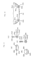
- Figure 7 is a perspective view showing the opening and closing cover of the apparatus opened
- Figure 8 is a perspective view illustrating the plastics hinge for the opening and closing cover, on an enlarged scale.
- the opening and closing cover 144 has a transparent window 144a through which one can see the remaining anmount of a tape to be played.
- the cover 144 is connected to the body casing 12a defining the tape cassette storage chamber 146 by means of the plastics hinge 142.
- the reason why the resin hinge 142 is used is to aim at reducing the number of components and making the apparatus lightweight.
- the speaker storage section 130 would inevitably have a large size. Accordingly, the increase of the speaker storage section 130 is naturally limited to a certain degree. Further, if the acoustic space is small, the sound quality in matters such as sound development, profundity or the like deteriorates. Therefore, in the apparatus, the remaining space in the tape cassette storage section 146 is effectively used as an auxiliary sound acoustic space while preventing, as far as possible, the space of the speaker storage section 130 from increasing. That is, a communication hole 132a is formed in a part of the partition wall 132 separating the speaker storage section 130 from the cassette storage chamber 146.
- the communication hole 132a allows the tape cassette storage chamber 146 in which the tape cassette 146a is loaded, to serve also as an acoustic space. It is therefore possible to obtain a reproduced sound having a relatively high sound quality despite the fact that the apparatus is compact.
- a plurality of slit holes 136 are formed on the rear side of the body casing 12a. That is, the entire surface of the speaker storage section 130 is covered with the mesh-like cover 134 while the rear surface of the speaker storage section is formed therein with the plurality of slit holes 136.
- the reason for the formation of the plurality of slit holes 136 is that a singer who grips the grip section 14 by one hand can hear his vocal sound increased by the speaker.
- the dimensions and the number of the slit holes 136 should be carefully considered so as to prevent the occurrence of howling because an increased sound coming from the grip section 14 side, if it is excessive, possibly acts as a feed-back sound transmitted to the microphone.
- the slit holes 136 have a dissipating action for heat generated from internal electronic parts. Further, in this apparatus, several narrow slit holes 136 are formed, and a fabric (which is not shown) is mounted on the inside thereof in order to prevent dust or the like from entering through the slit holes.
- a portable apparatus 2 for reproducing and amplifying sound according to a second embodiment of the present invention will be described hereinbelow.
- the apparatus 2 also mainly has a compact size, similar to the apparatus 1 of the first embodiment.
- the apparatus 2 has, as its maximum external dimensions, a height of 300 mm, a width of 100 mm and a depth of 121 mm, the total weight of the apparatus being 700g, including dry batteries.
- the apparatus 2 also mainly has an apparatus body 22, a grip section 24 and a microphone section 26 which are united together.
- the apparatus body section 22 is composed of a vocal sound medium storage section 220 for a tape cassette stored in a substantially rectangular parallelopiped body casing 22a and a speaker storage section 230.
- Push button members 220a, 220b, 220c, 220d, 220e for push button switches and volume rotary discs 230a, 230b project through the casing side surface of the vocal sound medium storage section 220.
- the push button member 220a is for stopping the feed of a magnetic tape
- the push button member 220b for fast-feeding the magnetic tape
- the push button member 220c for rewinding the magnetic tape
- the push button member 220d for playing the reproduction of a vocal sound signal recorded on the magnetic tape
- the push button member 220e as a start/stop pushing button member for returning a tape to a reproduction mode after completion of the "intro-scan" of a selected tune.
- the volume rotary disc 230a is for adjusting an echo of the microphone sound
- the volume rotary disc 230b is for adjusting the balance between the microphone sound volume and the tape reproduced sound volume.
- Each of the volume rotary discs 230a, 230b has an exposed surface having an area greater than that of a finger of an adult person, the surface having a semi-spherical projection m and a semispherical recess n formed thereon.
- Each of the knobs 130a, 130b in the first embodiment should be rotated while holding the knob between the thumb and the foreginger when it is manipulated.
- rotary discs 230a, 230b can be easily rotated by only one of the five fingers when it is manually operated, and consequently it can be used more easily.
- a volume rotary disc 230c provided on the other casing side surface as a vocal sound/music performance sound volume adjusting rotary disc for adjusting the balance between a vocal sound and a music performance sound upon reproduction of a sound multiplex tape, is also formed thereon with a semispherical projection m and a semispherical recess n.
- the push button member 230d for a push button switch positioned below the rotary disc 230c is a vocal sound muting push button member for decreasing a vocal sound volume while increasing a music performance sound volume when use is being made of a normal tape having a vocal song recorded thereon, rather than a sound multiplex tape.
- an input jack 230e is provided with an A.C. adapter during use of an external power source.
- the grip section 24 and the microphone section 26 which is integrally incorporated with the grip section 24 form a substantially cylindrical body, the microphone section 26 being positioned on the top of this cylindrical body. Further, resilient leg parts 232a, 232b project from the left and right sides of the lower part of the speaker storage section 230, and a resilient leg part 232c projects from the bottom part of the grip section 23.
- a manual operating section 28 is provided on the side surface of the cylindrical casing between the grip section 24 and the microphone section 26. The manual operating section 28 is provided thereon with a push button member 28b for a vocal sound assist switch for issuing a vocal sound from a tape only when it is continuously pushed for a long time.
- the virtually cylindrical grip section 24 is coupled integrally to the apparatus body section 22 by means of upper and lower coupling parts 20a, 20b. Between the grip section 24 and the apparatus body section 22, there is provided a through space 25 which enables the grip section 14 to be relatively freely gripped.
- FIG 10 is an exploded perspective view illustrating the casing of the apparatus 2.
- the casing of the portable audio reproducing and sound volume increasing apparatus 2 is, as in the first embodiment, mainly composed of a plastics body casing 22a, a plastics right half 24a and a plastics left half 24b.
- the right and left halves 24a, 24b are assembled integrally together by means of a screw S1.
- the body casing 22a is assembled to the thus obtained assembly by means of screws S2 to S5.
- the body casing 22a has an opening and closing cover 244 which is laterally operable. When the cover 244 is closed, a tape cassette storage chamber 246 is held in a complete air-tight condition.
- a speaker (which is not shown), similar to that described in the first embodiment, is disposed in the speaker storage section 230 in the body casing 22a, the speaker having its front surface covered by a mesh-like speaker cover 234.
- a cap 248 incorporated with a capacitor microphone is inserted in the upper end part of the cylindrical body which is formed of the right and left halves 24a, 24b united to each other, and the cap 248 is covered with a sponge protector member 250.
- the grip section 24 is not of a cylindrical shape having a uniform diameter, but it has a bulged part 24a which fits the palm of a human hand and which is accordingly easily held.
- a battery cover 24b is attached to the outer surface of the grip section 24, and batteries 24c are disposed inside the grip section 24.
- FIG 11 is a perspective view showing the relationship between the sponge protector member 250 and the cap 248.
- the sponge protector member 250 similar to the sponge protector member 150 in the first embodiment, is made of relatively low density foamed plastics (foamed urethane), and is formed therein with a cap fitting recess 250a.
- the capacitor microphone 248a is fitted in a circular hole in the top part of the cap 248.
- a felt member 258 is bonded to the pressure receiving surface of the capacitor microphone 248a.
- the upper part of the cap 248 has a substantially dome-like shape, and is formed therein with two kinds of elongated holes 248b, 248c extending radially from the capacitor microphone 248a as a centre, both kinds of elongated holes being arranged alternately of one another.
- the reason for providing these elongated holes 248b, 248c, which are similar to the elongated holes 148b and the circular holes 148c in the first embodiment, is that an excessive volume of sound from somebody singing is prevented from being reflected by the upper surface of the cap 248, so that the vibration of the pressure receiving surface of the microphone is not hindered.
- a feed-back sound propagating to the microphone from the inside of the casing is dispersed so as to prevent the occurrence of howling.
- the elongated holes 248c are formed, instead of the circular holes 148c in the first embodiment, in order to set the numerical aperture in the dome-like upper part of the cap 248 to a large value. Further, the height h of the dome-like part is set to a value which is greater than that of the cap 148 in the first embodiment, thereby to enhance further the above-mentioned effect.
- the cap 248 is fitted on a slightly reduced diameter end part 252a of the cylindrical casing 252 of the microphone section 26.
- An inner peripheral groove 252b is formed in the cylindrical end part 252a, and is fitted therein with a sound shield plate 255 which is a metal disc (made of iron).
- An upper sound absorbing member 257 made of relatively high density foamed plastics material (foamed urethane) is disposed on the upper side of the sound shield plate 255.
- the sound absorbing member 257 has excellent elasticity.
- Four node-like partition walls 259a to 259d are integrally incorporated with the cylindrical casing 252 below the inner peripheral groove 252b.
- the four node-like partition walls 259a to 259d are arranged parallel to the positioned sound shield plate 255, the partition walls 259a to 259d defining therein wire passage openings 260a to 260d which are positioned at opposite furthest positions on the diameter thereof, or alternately between those adjacent thereof.
- a wiring member 261 from the capacitor microphone 248a is led through passages between the upper sound absorbing member 258 and the inner surface of the casing and between the sound shield plate 255 and the inner surface of the casing, and then is led meandering through the wire passage openings 260a to 260d.
- a part of a feed-back sound wave propagating from the speaker (which is not shown) advances in the direction of the arrow in Figure 12.
- the greater part of the propagating sound wave is reflected or blocked by the node-like partition wall 259a. However, a part thereof is attenuated gradually through the wire passage port 260a, and comes out from the final wire passage opening 260d. Then it reaches the sound shield plate 255. However, a substantial part of the propagating wave is decayed by the four partition wall structure, that is by a labyrinth structure. When the propagating wave reaches the sound shield plate 255 which has a large specific gravity, the sound wave energy is absorbed, and is dissipated as heat. A part of the feed-back sound leaks to the upper side of the sound shield plate 255, but it is absorbed by the sound absorbing member 257.
- the partition wall structure or the labyrinth structure in this embodiment is formed integrally with the cylindrical casing 252, and accordingly, the number of components is reduced by comparison with that of the structure of the microphone section in the first embodiment.
- the resilient leg parts 232a, 232b which have a diameter of about 1 cm, project from the left and right sides of the lower part of the speaker storage section 230.
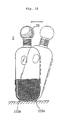
- the resilient leg part 232c which has a diameter of about 3 cm, projects from the bottom part of the grip section 24. Accordingly, the apparatus 2 can be set in a stationary posture with a three point support configuration as shown in Figure 9(f).
- the apparatus 1 in the first embodiment also has the integrally formed leg parts 132a, 132b, and accordingly, it may be set with three point support configuration by these two leg parts 132a, 132b and by the bottom part of the grip section 14.
- the stationary stability and the self-standing stability of the apparatus 1 are inferior to those of the apparatus 2 since the bottom part of the grip section 14 makes contact with the surface of a table or the like under a surface contact condition and since a casing made of hard materials is brought into direct contact with the surface.
- the stationary stability and the standing stability can be improved.
- the large diameter resilient leg part 232c is made of rubber, and is composed of a part-spherical member 233a projecting outside of the casing, a reduced diameter part 233b held between the split edges of the casing, and a removal prevention part 233c located in the casing, as shown in Figures 13(a) and 13(b).
- the small diameter resilient leg parts 232a, 232b are also made of rubber, and as shown in Figures 13(c) and 13(d), each of the leg parts has a resilient member 235 composed of a part-spherical member 234a projecting outside of the casing, a reduced diameter part 234b held between the split edges of the casing, and a removal prevention part 234c located in the casing.
- the resilient member 235 is formed therein with a hole in which a core member 234d is fitted.
- the core member 234d is made of a steel pipe and is formed in its peripheral surface with a zig-zag split 234f.
- the reason for using this zig-zag split 234f is that it gives a suitable strength to the resilient member 235 since in itself it has low durability and is likely to be damaged in view of its small diameter.
- the zig-zag split 234f formed in the core member 234d also has an anchoring function for preventing the core member 234d coming away from the resilient member 235, and can give an additional slight resiliency to the core member itself.
- the provision of the zig-zag split 234f is useful in this regard.
- the apparatus 2 even though the apparatus 2 is slightly inclined, the apparatus 2 itself has a tendency to recover to its upright standing posture with a tumbler action, due to not only the above mentioned three point support and slipping preventing function but also to a low centre of gravity positioning because of its relatively heavy weight.
- the recovery force can effectively prevent the apparatus 2 from overturning, and accordingly it is possible to reduce the possibility of damage or the like thereof.
- a "kara-oke" performance is carried out in darkness, the apparatus 2 itself is sometimes not clearly visible. Even in such a case, however, the apparatus 2 can be easily set on a table or the like without having to use particular care and this enables the apparatus 2 to be satisfactorily used.
- Figure 16 is a perspective view showing a state in which the opening and closing cover has been opened.
- a tape cassette 260 is loaded into the tape cassette storage chamber 246, as shown. Even when the tape cassette 260 has been so loaded, additional space exists in the tape cassette storage chamber 246.
- the storage chamber 246 is also functioning as an extension of a speaker acoustic space, similar to the cassette storage chamber 146 in the first embodiment.
- the partition wall 232 separating the speaker storage section 230 from the cassette storage chamber 246 is formed therein with communication holes 232a, 232b at opposite ends thereof.
- the communicating holes 232a, 232b and openings 262a, 262b allow the extra space in the tape cassette storage chamber 246 in which the tape cassette is loaded to serve also as an acoustic space for the speaker.
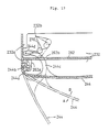
- Figure 17 is a sectional view showing a state in which the opening and closing cover has been opened and closed.
- a pair of support parts 262a integrally incorporated with the chassis 262 and a pair of support parts 244a of the opening and closing cover 244 are coupled together by a pin 244b, and accordingly the cover 244 can take a mid-opening position as indicated by the one-dot chain line in Figure 17 and a fully open position indicated by the two-dot chain line in the same figure.
- the cover 244 is integrally incorporated with a spiral arm 244c which passes through a through-hole 262b formed in the chassis 262, having its front end part entering into the deck storage chamber 30.
- a one-turn torsion spring 270 is hooked at opposite ends respectively in a hooking hole 232b formed in the partition wall 232 on the deck storage chamber side 30 and in a hooking hole 244d formed in the front end part of the spiral arm 244. Under the action of the torsion spring 270, a self-opening-and-closing force for the cover 244 can be obtained. At the mid-opening position as indicated by the one-dot chain line in Figure 17, the torsion spring 270 falls into its dead point condition.
- the cover 244 is automatically opened to the full open position as indicated by the two-dot chain line, while if the cover 244 is moved slightly in the direction of the arrow B, the cover is automatically closed to a closed position as indicated by the solid line. Accordingly, the cover 244 is always held at either the closed position indicated by the solid line or the full open position indicated by the two-dot chain line.
- the tape cassette can be loaded and unloaded without holding the opening and closing cover with one hand during loading and unloading of the tape cassette 260, and accordingly, the apparatus 2 can be easily handled during loading and unloading of a tape cassette.
- the apparatus 1 should be held in its substantially horizontal posture during loading and unloading of the tape cassette since the opening and closing cover is operated under the gravitational force.
- the cover can be held in its open position even though the apparatus is positioned in any posture, since the cover is not dependent upon the gravitational force, and accordingly, the apparatus 2 can be easily used.
- a part of the spring wire of the torsion spring 270 which passes through the hooking hole 244d serves as a resilient stopper when the cover is opened.
- a plurality of slit holes 236 are formed on the rear side of the body casing. These slit holes 236 allow a singer who grips the grip section 24 with one hand to hear his song which has its sound volume increased by the speaker, similar to the slit holes 136 in the first embodiment. Further, they give a heat radiation effect.
- the one difference from the first embodiment is that the slit holes 236 are formed so as to be directed downwards (toward the lower coupling part 20b), as shown in Figures 18(a) and 18(b). This arrangement prevents the sound from the speaker from propagating towards the microphone 248a so as to prevent occurrence of howling as far as possible.
- FIG 19 is a circuit block diagram showing a typical basic circuit arrangement for the portable apparatus for reproducing and amplifying sound according to this embodiment of the present invention.
- a sound multiplex tape cassette or other normal tape cassette i.e. a tape cassette recorded also with vocal sound
- a tape cassette on which musical tunes alone are recorded for a "kara-oke" performance can also be used.
- An explanation will be made hereinbelow of the circuit arrangement of the apparatus when used with a sound multiplex tape cassette as one example.
- the apparatus shown in Figure 19 is also composed of a sound reproducing system 50, a vocal sound input system 60 for inputting the sound of a singer, a mixing and amplifying system 70 and a speaker 80 as a transducer.
- the parts 50, 60, 70 are disposed in the vocal sound medium storage section 120 or 220, while the speaker 80 is disposed in the speaker storage section 130 or 230 which is spaced therefrom.
- the sound reproducing system 50 includes a vocal sound reproducing magnetic head 50a and a music tune reproducing magnetic head 50b which are attached to the tape deck.
- the magnetic heads 50a, 50b are arranged to produce signals derived respectively from a vocal track and from an orchestral or instrumental track on the tape used.
- a reproduced weak vocal sound signal from the magnetic head 50a is amplified by a pre-amplifier 50c, and is fed to the mixing and amplifying system 70 through resistors R1, R2. Further, a reproduced weak music tune or instrumental signal from the magnetic head 50b is amplified by a pre-amplifier 50d, and is fed to the mixing and amplifying system 70 through the resistors R3, R4.
- the vocal sound input system 60 for the inputting of the vocal sound from the singer includes the capacitor microphone 248a, a pre-amplifier 60a for amplifying a weak input vocal sound signal, a volume control 60b and a resistor R5, and the amplified signal is fed to the mixing and amplifying system 70 through the volume control 60b and the resistor R5.
- the mixing and amplifying system 70 includes a sound volume adjusting control 70a (linked to the volume adjusting dial 28a) and a power amplifier 70b as a driver for the small size speaker 80.
- a sound multiplex balance volume control 90a is disposed between the connecting point P1 of the resistors R1, R2 and the connecting point P2 of the resistors R3, R4, and a normally closed push switch 90c is disposed between the sliding element 90b of the balance volume control 90a and the ground.
- the resistance between opposite ends of the sound multiplex balance volume control 90a is R
- the resistance between the connecting point P1 and the sliding element 90b is r
- there is a reproduced vocal sound signal C1 which is the output of the resistor R1 and which leaks to the ground and attenuates through the resistance value r
- there is a reproduced music tune signal C2 which is the output of the resistor R3 and which leaks to the ground and attenuates through the resistance value R-r.
- the vocal sound i.e. the vocal sound from a professional singer derived from the tape
- the push switch 90c is linked to the push button member 28b for the vocal sound assist switch shown in Figure 9(c). Accordingly, if this push button member 28b is pressed, the push switch 90c is opened. The opening of the push switch 90c breaks the connection between the sliding element 90b and the ground, and accordingly the attenuation of the reproduced vocal sound signal C1 and the reproduced music tune signal C2 is interrupted, so that not only the music tune sound but also the vocal sound are transmitted from the speaker 80.
- the singer forgets the lyric lines of a song during his singing, and if he continuously presses the push button member 28b for the vocal sound assist switch for a long time, a vocal sound from a professional singer is transmitted from the speaker during this time, and accordingly, the singer can continue his singing while following this vocal sound.
- Figure 20 is a perspective view showing how the push button member for the vocal sound assist switch or the rotary volume adjusting member is manually operated by the thumb while holding the grip section by one hand.
- the rotary volume adjusting member 28a is located nearer to the grip section 24 than the push button member 28b for the vocal sound assist switch.
- the manual force applied to the rotary volume adjusting member 28 is in the direction indicated by the one-dot chain line arrow A shown in Figure 20, and the manual force applied to the push button member 28b for the vocal sound assist switch is in the direction indicated by the two-dot chain line arrow B shown in Figure 20.
- the flank of the thumb indicated by the one-dot chain line is brought into contact with the member 28a while moving the thumb in the direction of the one-dot chain line arrow A.
- the tip of the thumb can hardly touch the push button member 28b, and accordingly, there is no possibility of unexpectedly pressing the push button member 28b.
- the volume adjusting member 28a serves as a fulcrum, and the tip of the thumb is naturally spaced from the push button member 28b.
- the tip of the thumb presses it.
- the flank of the thumb makes contact with the volume adjusting member 28a.
- the tip of the thumb moves in the direction of the arrow B. Even though the flank of the thumb follows this motion so as to press the member 28a, the latter is not turned substantially since only a pressing force in the direction of the arrow B passing through the rotational centre of the member 28a is effected.
- Figure 21 is a circuit block diagram illustrating both the basic circuit block of the apparatus shown in Figure 19 and an electronic circuit system for an automatic tune "intro-scan" or scanning operation and starting device for locating a desired tune on a tape being used.
- Like reference numerals are used in Figure 21 to denote those like parts shown in Figure 19, and the description thereof is abbreviated.
- the electronic circuit system for the automatic tune scanning operation and starting device includes a scanning or head operation setting starting circuit 310, a inter tune gap detecting circuit 320 for detecting a gap between adjacent tunes on the tape, a detection completion sound generating circuit 330 and a motor stopping circuit 340.
- the scanning operation starting circuit 310 is a series circuit of leaf switches 310a, 310b which will be explained later and which are connected between a state selecting terminal 320a of the inter tune gap detecting circuit 320 and the ground.
- the two leaf switches 310a, 310b are normally closed, and accordingly, the state selecting terminal 320a of the inter tune gap detecting circuit 320 is at the ground potential (low potential) so that the inter tune gap detecting circuit 320 is held in a stationary state (de-energized condition).
- the leaf switch 310a is opened by being pressed with a pressing projection T of the fast-feed push button member 220b, and further, the leaf switch 310b is opened by being pressed with a pressing projection S of the rewinding push button member 220c.
- the state selecting terminal 320a of the inter tune gap detecting circuit 320 is at a potential higher than the ground potential, and accordingly, the inter tune gap detecting circuit 320 is turned into an energized condition (active condition).
- the inter tune gap circuit 320 has a so-called active-high circuit arrangement in which a reproduced and amplified vocal sound signal from the pre-amplifier 50c is inputted through a resistor R6 and a capacitor C, and a reproduced and amplified music tune signal from the preamplifier 50d is inputted through a resistor R7 and the capacitor C. That is, it receives both signals after they have been mixed, and detects a non-signal condition or a low level condition between the adjacent tunes, and delivers an inter tune gap detection signal when it is detected.
- the motor stopping circuit 340 stops the rotation of an electronic governor motor M for driving a reel in the tape cassette 260 using the inter tune gap detection signal from the inter tune gap detecting circuit 320 as a trigger signal.
- the detection completion sound generating circuit 330 delivers an information signal or an artificial vocal sound signal to the power amplifying device 70a through a resistor R8, using the above-mentioned inter tune gap detection signal as a trigger signal.
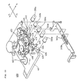
- FIG 22 is an exploded perspective view illustrating a tape deck 400 in the device
- Figures 23(a) to 23(f) are schematic plan views explaining the lock and unlock operations of the mechanism used in association with the manual operation of push buttons on the tape deck.
- the tape deck 400 comprises a number of components which are assembled on the front and rear surfaces of a plastics base board 401, as shown in Figure 22.
- Reel shafts 402, which project from the rear surface of the plastics base board 401, are fitted in reel holes in a tape cassette (not shown) when the latter is loaded.
- a play lever 404 on which is mounted a head assembly 403 including the reproducing magnetic head 50a and the music tune reproducing magnetic head 50b (see Figure 19), is slidably mounted on the plastics base board 401 for movement in directions Y+, Y ⁇ .
- the play lever 404 has an engagement member on which the play (reproducing) push button member 220d is mounted.
- a coil spring 406 acts between the play lever 404 and the plastics base board 401. The resiliency of the coil spring 406 exerts a return force on the play lever 404 in the direction of the arrow Y+.
- a lower slide plate 407 and an upper slide plate 408 are attached to the rear surface of the plastics base board 401.
- the lower slide plate 407 is slidable in the directions of the arrows X+, X ⁇ , and the resiliency of a torsion spring 407a exerts a return force on the lower side plate 407 in the direction of the arrow X ⁇ .
- the upper slide plate 408 is slidable on the lower slide plate 407 in the directions of the arrows X+, X ⁇ , and the resiliency of a coil spring 408a exerts a return force on the upper slide plate 408 in the direction of the arrow X ⁇ .
- another projection 413 on the play lever 404 presses an inclined surface of a pawl part 414 of the slide plate 407 so as to move the lower slide plate 407 in the direction of the arrow X+, so overcoming the spring force of the torsion spring 407a, the movement of the lower slide plate 407 being accompanied by that of the upper slide plate 408. Consequently, the projection 413 is engaged by the pawl part 414 so as to lock the play lever 404.
- the inter tune gap detecting circuit 320 When the leaf switch 310b is opened, as shown in Figure 21, the inter tune gap detecting circuit 320 is energized (placed in an active condition). During reproducing and rewinding modes, since the reproduced vocal sound signal and the reproduced music tune signal are inputted to the inter tune gap detecting circuit 320, the inter tune gap detecting circuit 320 detects a non-signal condition or a low level condition between the adjacent tunes, and delivers an inter tune gap detection signal. When the inter tune gap detection signal is delivered, the motor stopping circuit 340 stops the rotation of the electronic governor motor M for driving a reel, using the inter tune gap detection signal as a trigger signal.
- the detection completion sound generating circuit 330 delivers an information signal or an artificial voice signal to the power amplifying device 70a through the resistor R8, using the inter tune gap detection signal as a trigger signal. Accordingly, an information signal or an artificial voice signal is issued from the speaker 80.
- a known tape recorder converts this signal into a mechanical drive force by means of a solenoid plunger or the like so as to actuate a release lever or the like in order to release the play lever 404 or the rewinding lever 415, thereby stopping the motor M.
- a solenoid plunger Upon the start of this solenoid plunger, several Amperes of current are consumed immediately.
- the rewinding mode is electrically locked, the consumption of power is still large.
- the rewinding lever 415 When the rewinding lever 415 is returned in the direction of the arrow Y+, the pressing projection S moves away from one of contact pieces of the leaf switch 310b, and accordingly, the leaf switch 310b is returned to its normally closed condition. Accordingly, since the state selection terminal 320a of the inter tune gap detecting circuit 320 is at the ground potential, the inter tune gap detecting circuit 320 is shifted into the inactive condition. In association with the shift into the inactive condition, the stopping action of the motor stopping circuit 340 is released, and accordingly, the motor M is rotated so as to go back to the play (reproducing) mode. That is, after completion of the scanning operation, the mode is shifted into the play (reproducing) mode only by one manual operation for pushing the start lever 420.
- the start lever 420 has an engagement member 428 onto which the start push button member 220e is fitted.
- a fast-feed lever 430 is pushed in the direction of the arrow Y ⁇ , so overcoming the spring force of the torsion spring 416 from the reproducing condition shown in Figure 23(b)
- an inclined part of a pawl part 431 presses a projection 432 on the upper slide plate 408, and accordingly, the upper slide plate 408 is moved in the direction of the arrow Y+, so overcoming the spring force of the coil spring 406, relative to the lower spring 407. Therefore, the pawl part 431 engages with the projection 432 so that the fast-feed lever 430 is locked.
- the fast-feed lever 430 has an engagement member 433 onto which the fast-feed push button top 220b is fitted. Meanwhile, during the process of sliding of the fast-feed lever 430 in the direction of the arrow Y+, the pressing projection T on the fast-feed button member 220b shown in Figure 22 presses one of contact pieces of the leaf switch 310a which is therefore opened.
- the leaf switch 310a is opened in a similar way to the opening of the above-mentioned leaf switch 310b, the inter tune gap detecting circuit 320 is shifted to an energized condition (active condition) so as to carry out the automatic scanning operation.
- the fast feed lever 430 When the fast feed lever 430 is returned in the direction of the arrow Y+, the pressing projection T moves away from the one of contact pieces of the leaf switch 310a which is therefore closed. Thereby, the state selection terminal 320a of the inter tune gap detecting circuit 320 is at the ground level so that the inter tune gap detecting circuit 320 is shifted into the inactive condition.
- the issuance of the information sound or the artificial voice sound caused by the pushin operation of the fast-feed lever 430 indicates that it is the heading of the next music tune, jumping over a music tune on reproduction.
- the start lever 420 is automatically returned to the condition shown in Figure 23(b) by the spring force of the torsion spring 407a. That is, the play (reproducing) mode is retrieved.
- the start lever 420 has an engagement member 428 onto which the start push button member 220e is fitted.
- the release lever 425 which has an engagement member 440 onto which the release push button member 220a is fitted, is urged in the direction of the arrow Y+ by the spring force of a torsion spring which is not shown. Further, the release lever 425 has a projection 441.
- the upper slide plate 408 and lower slide plate 407 have pawl parts 442, 443 against which the projection 441 abuts (see Figures 23(d) and 23(f)).
- the projection 441 presses both pawl parts 442, 443 against which it abuts so as to move both the upper slide plate 408 and the lower slide plate 407 in the direction of the arrow X+.
- the engagement between the projection 413 and the pawl part 414 is released so as to release the lock condition of the play lever 404.
- the projection 441 on the release lever 425 abuts against the pawl parts 442, 443, individually, so as to release the fast-feed condition and the rewinding condition, respectively, during the non-reproducing mode.
- the reproduced sound volume is restricted during play mode without loading a tape cassette in the apparatus, it can be also used as a loudspeaker.
- a vocal sound by a professional singer or the like can be issued by operating the signal intensity setting means after previously adjusting the signal intensity changing means, when a part of the lyric lines of a song cannot be sung during a "kara-oke" performance. Accordingly, the singer can continue signing the lyric lines of the song while hearing the vocal sound.
- a start signal generating means for producing a heading setting operation start signal at the time of fast forward feed operation or fast rearward feed operation during the reproducing mode
- a motor stopping circuit for stopping the supply of power to a drive motor for a vocal sound reproducing device in association with a detection signal from the inter tune gap detecting circuit
- the motor can be directly and electrically stopped without forcibly releasing the locked condition of the mechanism system for fast forward feed or fast rearward feed upon completion of the music tune scanning operation. Accordingly, substantially no current is consumed upon the stopping of the motor after completion of the tune scanning operation. Consequently it is possible to save the power of an incorporated power source of the like.
- the restart (the reproduction from the heading of a tune) can be made merely by one operation of pushing the start lever, and accordingly, the apparatus is easily operable.
Landscapes
- Engineering & Computer Science (AREA)
- Physics & Mathematics (AREA)
- Acoustics & Sound (AREA)
- Signal Processing (AREA)
- Multimedia (AREA)
- Reverberation, Karaoke And Other Acoustics (AREA)
Applications Claiming Priority (6)
| Application Number | Priority Date | Filing Date | Title |
|---|---|---|---|
| JP4405/90U | 1990-01-22 | ||
| JP440590 | 1990-01-22 | ||
| JP1132190 | 1990-02-07 | ||
| JP11321/90U | 1990-02-07 | ||
| JP290230/90 | 1990-10-26 | ||
| JP2290230A JPH03278083A (ja) | 1990-01-22 | 1990-10-26 | 携帯型音声再生及び拡声装置 |
Publications (2)
| Publication Number | Publication Date |
|---|---|
| EP0439309A2 true EP0439309A2 (de) | 1991-07-31 |
| EP0439309A3 EP0439309A3 (en) | 1992-11-25 |
Family
ID=27276257
Family Applications (1)
| Application Number | Title | Priority Date | Filing Date |
|---|---|---|---|
| EP19910300433 Withdrawn EP0439309A3 (en) | 1990-01-22 | 1991-01-18 | Apparatus for reproducing and amplifying sound |
Country Status (1)
| Country | Link |
|---|---|
| EP (1) | EP0439309A3 (de) |
Cited By (5)
| Publication number | Priority date | Publication date | Assignee | Title |
|---|---|---|---|---|
| GB2267599A (en) * | 1992-06-02 | 1993-12-08 | Peter Noble | Magnetic sound mixer. |
| FR2714759A1 (fr) * | 1993-12-30 | 1995-07-07 | Dziulko Adolphe | Magnétophones à quatre pistes et cassettes préenregistrées. |
| GB2288054A (en) * | 1994-03-31 | 1995-10-04 | James Young | A wireless karaoke microphone |
| EP1691688B1 (de) * | 2003-12-04 | 2008-08-20 | Koninklijke Philips Electronics N.V. | Ergonomisches gehäuse für eine ultraschallwandlersonde |
| CN101778333B (zh) * | 2010-01-27 | 2013-01-16 | 杭州华三通信技术有限公司 | 一种麦克风状态的检测方法和装置 |
Families Citing this family (1)
| Publication number | Priority date | Publication date | Assignee | Title |
|---|---|---|---|---|
| RU2148862C1 (ru) * | 1999-09-20 | 2000-05-10 | Ровнер Яков Шоел-Берович | Мобильная система караоке, способ обеспечения электромагнитной совместимости для мобильной системы караоке, мобильное беспроводное передающее устройство для нее, картридж для нее, способ предотвращения использования неавторизованных картриджей в ней и способ для предотвращения несанкционированного доступа к данным в ней |
Family Cites Families (1)
| Publication number | Priority date | Publication date | Assignee | Title |
|---|---|---|---|---|
| WO1989009470A1 (fr) * | 1988-03-31 | 1989-10-05 | Seiko Epson Corporation | Reproducteur d'enregistrements portatif |
-
1991
- 1991-01-18 EP EP19910300433 patent/EP0439309A3/en not_active Withdrawn
Cited By (7)
| Publication number | Priority date | Publication date | Assignee | Title |
|---|---|---|---|---|
| GB2267599A (en) * | 1992-06-02 | 1993-12-08 | Peter Noble | Magnetic sound mixer. |
| FR2714759A1 (fr) * | 1993-12-30 | 1995-07-07 | Dziulko Adolphe | Magnétophones à quatre pistes et cassettes préenregistrées. |
| GB2288054A (en) * | 1994-03-31 | 1995-10-04 | James Young | A wireless karaoke microphone |
| US5606143A (en) * | 1994-03-31 | 1997-02-25 | Artif Technology Corp. | Portable apparatus for transmitting wirelessly both musical accompaniment information stored in an integrated circuit card and a user voice input |
| GB2288054B (en) * | 1994-03-31 | 1998-04-08 | James Young | A microphone |
| EP1691688B1 (de) * | 2003-12-04 | 2008-08-20 | Koninklijke Philips Electronics N.V. | Ergonomisches gehäuse für eine ultraschallwandlersonde |
| CN101778333B (zh) * | 2010-01-27 | 2013-01-16 | 杭州华三通信技术有限公司 | 一种麦克风状态的检测方法和装置 |
Also Published As
| Publication number | Publication date |
|---|---|
| EP0439309A3 (en) | 1992-11-25 |
Similar Documents
| Publication | Publication Date | Title |
|---|---|---|
| US5349480A (en) | Portable audio apparatus | |
| US20080156180A1 (en) | Guitar and accompaniment apparatus | |
| JP2002091614A (ja) | 携帯型電子機器 | |
| US8300504B2 (en) | Switch device, information processing device, and reproduction device | |
| EP0439309A2 (de) | Gerät zur Wiedergabe und Verstärkung von Schallsignalen | |
| US5225944A (en) | Portable audio apparatus | |
| US4419749A (en) | Magnetic reproducing apparatus capable of receiving radio broadcast programs | |
| US5214543A (en) | Portable audio apparatus having a power savings device | |
| US4488273A (en) | Magnetic reproducing apparatus capable of receiving radio broadcast programs | |
| JPH03278083A (ja) | 携帯型音声再生及び拡声装置 | |
| CN1028707C (zh) | 便携型音频重放和扩音装置 | |
| US20080232614A1 (en) | Sound amplifier with speaker | |
| US5323370A (en) | Children's music player with control lockout | |
| EP0875818A2 (de) | Tragbarer Rechner mit unverdeckten Lautsprechern und zugehörigen Tonsignal-Bedienungstasten | |
| EP2107822A1 (de) | Klangverstärker mit Lautsprecher | |
| GB2254475A (en) | Sound reproducer and/or loudspeaker system | |
| JPS59204398A (ja) | カラオケ用マイクロホン | |
| CA2352706C (en) | Hand karaoke equipment | |
| JP2673935B2 (ja) | カラオケの歌声を録音したテープの販売装置 | |
| KR100432858B1 (ko) | 어학 학습기 | |
| JPH06349259A (ja) | 楽器付き記録及び/又は再生装置 | |
| JPH079518Y2 (ja) | 携帯型音声再生及び拡声装置 | |
| JPS6235186Y2 (de) | ||
| KR950005685Y1 (ko) | 디지탈 피아노의 오디오 카세트 장착구조 | |
| KR200158102Y1 (ko) | 스피커 유닛용 테이블의 리모컨 보관 장치 |
Legal Events
| Date | Code | Title | Description |
|---|---|---|---|
| PUAI | Public reference made under article 153(3) epc to a published international application that has entered the european phase |
Free format text: ORIGINAL CODE: 0009012 |
|
| AK | Designated contracting states |
Kind code of ref document: A2 Designated state(s): DE FR GB |
|
| PUAL | Search report despatched |
Free format text: ORIGINAL CODE: 0009013 |
|
| AK | Designated contracting states |
Kind code of ref document: A3 Designated state(s): DE FR GB |
|
| 17P | Request for examination filed |
Effective date: 19930427 |
|
| 17Q | First examination report despatched |
Effective date: 19940714 |
|
| STAA | Information on the status of an ep patent application or granted ep patent |
Free format text: STATUS: THE APPLICATION IS DEEMED TO BE WITHDRAWN |
|
| 18D | Application deemed to be withdrawn |
Effective date: 19941125 |