EP0439346A2 - Foyer à gaz - Google Patents
Foyer à gaz Download PDFInfo
- Publication number
- EP0439346A2 EP0439346A2 EP91300526A EP91300526A EP0439346A2 EP 0439346 A2 EP0439346 A2 EP 0439346A2 EP 91300526 A EP91300526 A EP 91300526A EP 91300526 A EP91300526 A EP 91300526A EP 0439346 A2 EP0439346 A2 EP 0439346A2
- Authority
- EP
- European Patent Office
- Prior art keywords
- burner
- fire
- slot
- slots
- flame
- Prior art date
- Legal status (The legal status is an assumption and is not a legal conclusion. Google has not performed a legal analysis and makes no representation as to the accuracy of the status listed.)
- Withdrawn
Links
Images



Classifications
-
- F—MECHANICAL ENGINEERING; LIGHTING; HEATING; WEAPONS; BLASTING
- F24—HEATING; RANGES; VENTILATING
- F24C—DOMESTIC STOVES OR RANGES ; DETAILS OF DOMESTIC STOVES OR RANGES, OF GENERAL APPLICATION
- F24C3/00—Stoves or ranges for gaseous fuels
- F24C3/002—Stoves
- F24C3/006—Stoves simulating flames
Definitions
- This invention relates to a gas fire which is particularly but not exclusively a decorative fuel effect gas fire.
- One such problem is that the burner material (usually stainless steel) tends to degrade in time due to excessive downward radiation of the fire.
- a further problem is the tendency for various control mechanisms of the gas fire to overheat due to the open nature of the burner assembly employed which allows an overspill of downward radiation onto the controls.
- a problem which tends to be more pronounced with gas fires that run on L.P.G. (liquid petroleum gas) is the amount of sooty products created which, of course, tends to affect the efficiency of the fire and close off or partially close off burner ports effecting flame formation.
- An object of the present invention is to at least alleviate one or more of the aforementioned problems, or other problems associated with gas fires more particularly but not exclusively of a decorative fuel effect type, and/or to provide a gas fire which is improved in at least some respect.
- a gas fire comprising a ribbon-type burner as herein defined.
- a ribbon-type burner is herein defined as a burner having an elongate slot which in use is capable of forming a ribbon or sheet of flame.
- a disadvantage of most ported burners is that they have a defined inner core as aforementioned, which tends to produce a fire that looks more artificial than real and generally the tendency for the ribbon-type burner will be for a much more uniform and uniformly coloured ribbon of flame to be produced rather than multi-coloured flames being produced individually from individual burner ports.
- the gas fire may be a decorative fuel effect fire.
- the burner provides two spaced burner slots. These slots are preferably parallel and will usually be arranged across the front of the fire to provide two parallel generally vertically directed parallel ribbons of flame running across the front of the gas fire.
- the burner is preferably shielded from downward radiation of the fire by insulating material and where two spaced burner slots are provided, the burner is preferably shaped to receive one or more blocks of insulating material spanning the gap between the spaced burner slots.
- the burner may advantageously be constructed from mild steel rather than stainless steel.
- the fire may be designed in practice to allow secondary air in and around the burner slot/s to provide an additional cooling effect.
- a hotter flame than normal may be provided for, thus increasing the efficiency and radiant output of the fire by the generation of a hotter flame.
- the use of a ribbon type burner in the gas fire should allow a close control of primary aeration and a higher degree of aeration with a greater net output. This is particularly important with gas fires running on L.P.G. since such fires need a lot of primary air and have a high soot effect which can affect the burner if not enough primary air is available.
- the burner is provided with an internal baffle located centrally at the front of the burner adjacent a front burner slot in order to stop localised high velocity effects and to provide a uniform flow distribution across the front slot.
- the burner may be fabricated and may be constructed by spot welding and/or rivetting an outer casing (which is punched out of sheet metal and folded into shape) to an inner cup shaped portion.
- the outer casing may be provided with a hole into which a burner gas mixing tube can be inserted.
- the or each burner slot has a port depth of about 12 mm in order to ensure that lightback is prevented.
- Constructing the burner in the aforedescribed manner allows the fire to be produced without expensive special tooling (the tooling costs for the burner could be about £60,000) but eventually the burner may be deep drawn on such special tooling which will allow the burner to be produced at a cost of about one quarter of the costs involved in a fabrication process.
- the fabrication process does allow a burner of a variable size to be produced and without the initial expensive outlay for special tooling.
- the burner produced by a fabrication process may provide a number of slot portions along the or each burner slot in order to avoid deviations or deformations in the size of the slot width over the length of the slot and also to provide a strong structure.
- the front slot width is preferably less than the slot width of the rear slot in order to provide a more real effect for a decorative fuel effect gas fire.
- the front slot width may be about 1 mm and the rear slot width about 1.8 mm.
- one of the slots (rear slot) lights first and the other slot (front slot) cross lights off the rear slot by roll-over action of the flame. It is possible that cross-lighting from the front to rear slot could be arranged if preferred.
- baffle means may be located above the slot and conveniently, where insulating material is provided as aforesaid to shield the burner from downward radiation, the baffle means is provided by an overhanging lip on this insulating material. The baffle means creates a local turbulence to assist in such "flash-over" ignition of the burner slot portions.
- the bed of the fire is preferably provided with insulating material in order to reduce downward radiation of the fire and/or baffle means is provided to protect control means of the fire from downward radiation.
- This insulating material may be a soft ceramic fibre board which in use supports decorative coals of the fire, said coals also possibly being supported by the insulating material which protects the burner from downward radiation.
- a ribbon-type burner as herein defined for a gas fire, said burner, preferably, having at least two spaced ribbon burner slots to provide two spaced ribbons or sheets of flame in use in a gas fire.
- the burner may be constructed from an outer casing and an inner cup-shaped portion which in use may receive a block of insulating material to shield the burner from downward radiation of the fire.
- the burner provides two parallel ribbons of flame with slot areas at each end of the burner being closed off.
- the burner may include an internal centrally located baffle adjacent to one of the slots.
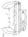
- a decorative fuel effect gas fire 1 has opposed ceramic side plaques 2; rear, angled, soft ceramic fibre-board fibre bed 3 (which in use supports vermiculite coals -only shown diagrammatically in FIGURE 5), and a front simulated coal piece 4 providing the effect of a row of coals along the front of the fire.
- Side plaques 2, fibre bed 3 and coal piece 4 are omitted from FIGURE 2.
- a burner 5 (see FIGURES 3 and 6 to 8 in particular) seats an insulating, ceramic block or burner insert 6 (omitted from FIGURE 2) in a channel defined between front and rear slots 5a, 5b of the ribbon-type burner 5.
- FIGURES 4 A general schematic over-view of the fire is shown from above in FIGURES 4 and 5.
- FIGURE 4 shows a view of the fire prior to placing the loose coals C (see FIGURE 5) onto the fire and FIGURE 5 shows how the coals can be located. As will be apparent from FIGURE 5 the coals will extend over and be supported by insulating block 6 (in fact FIGURE 4 shows the insulating block 6 being split into two parts).
- the ribbon-type burner 5 is arranged to produce two parallel vertically ensuing ribbons or sheets of flame by way of the front and rear slots 5a and 5b.
- each sheet or continuous "ribbon of flame” is generally of a uniform colour and this helps to provide a more real looking decorative fuel effect fire than the flames produced from normal ported type burners having pierced ports which usually provide a highly defined inner core identifying the flame source clearly as a "gas burner".
- the burner 5 is suitable for use with natural gas and is particularly suitable with L.P.G., and is based on a generally conventional ported/aerated type entraining 60% of its primary stoichiometric air requirement for combustion purposes.
- the burner 5 differs from usual ported type burners in its design and construction and most importantly in the design of the ribbon slots rather than pierced ports.
- the burner itself is shown in FIGURES 6 to 8 of the accompanying drawings.
- the burner 5 as shown is constructed from an outer casing 5c and inner cup-shaped member 5d.
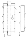
- the outer casing 5c is made from the sheet steel component blank shown in FIGURE 9 (FIGURE 10 shows the blank in FIGURE 9 folded into place in plan view) which is folded into the required shape and spot-welded to the inner member 5d at the ends thereof as indicated by the spot welds S.
- depressions D are provided on the outer casing 5d as shown best in FIGURES 6 and 8.
- the depressions D also provide spot weld areas for welding the outer casing 5c to the inner member 5d and, in this instance, a number of slot portions P are defined along the length of each slot 5a, 5b inbetween the depressions.
- slot portion design shown in FIGURES 6 to 8 is slightly different to the slot portion divisions shown in the burner in FIGURES 1 to 3 and indeed any suitable number of slot portions could be provided depending upon design constraints.
- Each slot 5a, 5b is divided into slot portions in order to provide a strong construction and to ensure that the width W1, W2 of the slot 5a, 5b does not vary or deform along the length.
- a hole H is provided in the outer casing 5c to receive the burner gas mixing tube M and tube M may be either brazed or pressed into position.
- FIGURE 8 shows a ringed side-view detail E of an alternative rivetting attachment (ringed in a chain-dotted line on FIGURE 8) rather than spot welded joints.
- the burner 5 provides a port depth p of about 12 mm (see FIGURE 7) in order to avoid light-back and a baffle B is located centrally at the front of the burner adjacent to the front slot 5a.
- the baffle B is attached to the inner member 5d and extends downwardly therefrom a distance which is nearly equal to the depth of the burner but only extends a short distance Y parallel to the slot 5a (see FIGURE 6).
- the baffle B which is in the shape of a right angle is welded to the bottom of the inner member 5d by spot welds S2. Baffle B stops localised high velocity flow and gives uniform distribution to the flame across the front slot 5a.
- the slot width W1 of the front slot 5a is about 1 mm whereas the slot width of the rear slot 5b is about 1.8 mm.
- the gas issuing from the rear slot 5b is lit first and the gas issuing from the front slot 5a is cross lit from the rear slot by a roll-over action of the flame.
- the coals C being situated on the soft ceramic fibre bed 3 and also on the insulating block 6 assist in the roll-over effect.
- the insulating block 6 Since the insulating block 6 is seated in the burner 5 it shields the main area of the burner from the incandescent area of the fire bed. The amount of downward radiation is dramatically reduced and only a small strip of the burner 5 (the area surrounding the slots 5a and 5b) is exposed to downward radiation. In any event, this strip area of the burner 5 is cooled by the rushing effect of secondary air along the burner 5 immediately adjacent to the slots 5a,5b . Secondary air is able to flow into the gas fire 1 and around the burner slots 5a and 5b along the path of the arrows shown in FIGURE 3. It is important that the burner 5 is shielded from the downward radiation because it prevents or alleviates degradation of the burner material and, thus, the burner could be constructed from mild steel rather than stainless steel if preferred.
- the design of the burner 5 allows a high degree of primary aeration which generates a hotter flame at the slots 5a and 5b but because of the protection from downward radiation provided by the insulating block 6 and because of the secondary air flowing around the slots the heat from the burner itself can be dissipated quickly, thereby allowing a net radiant output of the fire 1 at a higher level without incurring the disadvantages associated with burner degradation.
- the temperature of the upper surface 3a of the fibre bed 3 can be very hot (for example 1000°C) giving the appearance of a very hot fire whilst the temperature of the bottom 3b of the fibre bed can be as low as 200°C.
- the soft ceramic fibre of the fibre bed 3 can be maintained at a higher temperature than would be generated from a sand or vermiculite bed type of burner. Additionally the sizing of the air mixing tube M allows a high degree of primary aeration.
- a further detail of the fire is the provision of lips L1, L2 on the insulating block 6 (see FIGURE 3) which provide baffle means above the slots 5a and 5b. The lips L1 and L2 help to create local turbulence above the slots 5a and 5b and thus encourage flash-over from one slot portion P to another along the slots 5a and 5b.
- gas fire 1 has a further baffle Z (see FIGURE 3) to help protect the control means A from downward radiation.
- any range mentioned herein for any variable or parameter shall be taken to include a disclosure of any derivable sub-range within that range or of any particular value of the variable or parameter arranged within, or at an end of, the range or sub-range.
- Figures 11 and 12 show views of an alternative embodiment of the present invention. It is an advantage of both fires that the burner/s provide low nitrous oxide emissions. Most advantageously, secondary air in both embodiments is provided in and around the burner/s to reduce burner temperature with low nitrous oxide emissions. Advantageously, the burner/s are shielded from downward radiation.
Landscapes
- Engineering & Computer Science (AREA)
- Chemical & Material Sciences (AREA)
- Combustion & Propulsion (AREA)
- Mechanical Engineering (AREA)
- General Engineering & Computer Science (AREA)
Applications Claiming Priority (2)
| Application Number | Priority Date | Filing Date | Title |
|---|---|---|---|
| GB9001638A GB2228794B (en) | 1990-01-24 | 1990-01-24 | Gas fire |
| GB9001638 | 1990-01-24 |
Publications (2)
| Publication Number | Publication Date |
|---|---|
| EP0439346A2 true EP0439346A2 (fr) | 1991-07-31 |
| EP0439346A3 EP0439346A3 (en) | 1991-10-16 |
Family
ID=10669835
Family Applications (1)
| Application Number | Title | Priority Date | Filing Date |
|---|---|---|---|
| EP19910300526 Withdrawn EP0439346A3 (en) | 1990-01-24 | 1991-01-24 | Gas fire |
Country Status (2)
| Country | Link |
|---|---|
| EP (1) | EP0439346A3 (fr) |
| GB (1) | GB2228794B (fr) |
Cited By (3)
| Publication number | Priority date | Publication date | Assignee | Title |
|---|---|---|---|---|
| EP0952401A1 (fr) * | 1998-04-24 | 1999-10-27 | Fonderie Du Der SA | Dispositif de brûleur pour cheminée à insert à gaz |
| DE19920772B4 (de) * | 1999-04-03 | 2004-04-01 | Fritz Trinker | Gas-Brenner, insbesondere für einen Heizofen oder offenen Kamin |
| US20140338651A1 (en) * | 2013-05-14 | 2014-11-20 | Fenix Outdoor AB | Burner for a portable stove and portable stove |
Families Citing this family (1)
| Publication number | Priority date | Publication date | Assignee | Title |
|---|---|---|---|---|
| GB2302939A (en) * | 1995-07-04 | 1997-02-05 | Le Baigue Magiglo Limited | Decorative gas fires |
Family Cites Families (8)
| Publication number | Priority date | Publication date | Assignee | Title |
|---|---|---|---|---|
| GB2109536A (en) * | 1981-11-12 | 1983-06-02 | Melda Enterprises | Solid fuel effect gas fires |
| GB2149086B (en) * | 1983-10-12 | 1987-04-15 | David Arthur Allen | Solid fuel effect gas fire |
| GB8329992D0 (en) * | 1983-11-10 | 1983-12-14 | Beaumont Ltd John L | Space heating appliances |
| US4582478A (en) * | 1985-08-26 | 1986-04-15 | Hilker Gloria D | Valve operated alcohol log and burner assembly |
| GB2205771B (en) * | 1987-06-18 | 1991-01-02 | Energy Facilities Management | Forge hearth |
| GB8717673D0 (en) * | 1987-07-25 | 1987-09-03 | Glynwed Consumer & Building | Gas fire |
| GB2208703A (en) * | 1987-08-14 | 1989-04-12 | Grate Glow Fires | Fuel effect gas fires |
| GB8723755D0 (en) * | 1987-10-09 | 1987-11-11 | Valor Heating Ltd | Gas burners |
-
1990
- 1990-01-24 GB GB9001638A patent/GB2228794B/en not_active Expired - Fee Related
-
1991
- 1991-01-24 EP EP19910300526 patent/EP0439346A3/en not_active Withdrawn
Cited By (4)
| Publication number | Priority date | Publication date | Assignee | Title |
|---|---|---|---|---|
| EP0952401A1 (fr) * | 1998-04-24 | 1999-10-27 | Fonderie Du Der SA | Dispositif de brûleur pour cheminée à insert à gaz |
| DE19920772B4 (de) * | 1999-04-03 | 2004-04-01 | Fritz Trinker | Gas-Brenner, insbesondere für einen Heizofen oder offenen Kamin |
| US20140338651A1 (en) * | 2013-05-14 | 2014-11-20 | Fenix Outdoor AB | Burner for a portable stove and portable stove |
| US11002448B2 (en) * | 2013-05-14 | 2021-05-11 | Fenix Outdoor AB | Burner for a portable stove and portable stove |
Also Published As
| Publication number | Publication date |
|---|---|
| GB9001638D0 (en) | 1990-03-21 |
| GB2228794A (en) | 1990-09-05 |
| GB2228794B (en) | 1994-06-29 |
| EP0439346A3 (en) | 1991-10-16 |
Similar Documents
| Publication | Publication Date | Title |
|---|---|---|
| US4875464A (en) | Clean burning gas log burner system | |
| US5081981A (en) | Yellow flame gas fireplace burner assembly | |
| EP1776028B1 (fr) | Appareil d'emission infrarouge | |
| US6095794A (en) | Fireplace burner apparatus | |
| US4838240A (en) | Fireplace gas burner assembly | |
| EP0599864B1 (fr) | Bruleur a gaz a elements ceramiques perfores | |
| US5320520A (en) | Gas burner assembly for simulating a natural log fire | |
| GB2284476A (en) | Simulated solid fuel gas fires | |
| CN115127104A (zh) | 火排及其制造方法、燃烧器和热水器 | |
| DE69821362T2 (de) | Verfahren und vorrichtung zur verminderung der co- und nox-emissionen in einem heizgerät | |
| US5392763A (en) | Gas burner system | |
| GB2182431A (en) | Gas fire | |
| GB2081885A (en) | Simulated solid fuel gas firée | |
| EP0439346A2 (fr) | Foyer à gaz | |
| US5931154A (en) | Gas fireplace burner plate | |
| CA2174198A1 (fr) | Systemes de bruleurs pour foyers au gaz | |
| US5671727A (en) | Configurable low profile gas fireplace burner | |
| GB2160642A (en) | Gas fire | |
| DE4406446A1 (de) | Heizeinrichtung für gasförmige Brennstoffe | |
| GB2109536A (en) | Solid fuel effect gas fires | |
| US4964397A (en) | Fireplace construction | |
| US4542735A (en) | Gas fires | |
| GB2147994A (en) | Gas fire | |
| DE69014715T2 (de) | Gasbrenner. | |
| GB2119921A (en) | Fuel-effect gas fire |
Legal Events
| Date | Code | Title | Description |
|---|---|---|---|
| PUAI | Public reference made under article 153(3) epc to a published international application that has entered the european phase |
Free format text: ORIGINAL CODE: 0009012 |
|
| AK | Designated contracting states |
Kind code of ref document: A2 Designated state(s): BE DE ES FR GB NL |
|
| PUAL | Search report despatched |
Free format text: ORIGINAL CODE: 0009013 |
|
| AK | Designated contracting states |
Kind code of ref document: A3 Designated state(s): BE DE ES FR GB NL |
|
| 17P | Request for examination filed |
Effective date: 19920411 |
|
| 17Q | First examination report despatched |
Effective date: 19920911 |
|
| STAA | Information on the status of an ep patent application or granted ep patent |
Free format text: STATUS: THE APPLICATION IS DEEMED TO BE WITHDRAWN |
|
| 18D | Application deemed to be withdrawn |
Effective date: 19940722 |