EP0439348B1 - Procédé et appareil pour décharger des composants empaquetés sur une bande de transport - Google Patents
Procédé et appareil pour décharger des composants empaquetés sur une bande de transport Download PDFInfo
- Publication number
- EP0439348B1 EP0439348B1 EP91300529A EP91300529A EP0439348B1 EP 0439348 B1 EP0439348 B1 EP 0439348B1 EP 91300529 A EP91300529 A EP 91300529A EP 91300529 A EP91300529 A EP 91300529A EP 0439348 B1 EP0439348 B1 EP 0439348B1
- Authority
- EP
- European Patent Office
- Prior art keywords
- component
- knife
- tape carrier
- packaging assembly
- cavity
- Prior art date
- Legal status (The legal status is an assumption and is not a legal conclusion. Google has not performed a legal analysis and makes no representation as to the accuracy of the status listed.)
- Expired - Lifetime
Links
- 238000004806 packaging method and process Methods 0.000 title claims description 27
- 238000000034 method Methods 0.000 title claims description 12
- 238000005520 cutting process Methods 0.000 claims description 11
- 239000004033 plastic Substances 0.000 claims description 6
- 229920003023 plastic Polymers 0.000 claims description 6
- 239000000463 material Substances 0.000 claims description 4
- 230000003213 activating effect Effects 0.000 claims 1
- 230000007246 mechanism Effects 0.000 description 16
- 239000007787 solid Substances 0.000 description 4
- 239000000969 carrier Substances 0.000 description 2
- 238000004519 manufacturing process Methods 0.000 description 2
- 238000012986 modification Methods 0.000 description 2
- 230000004048 modification Effects 0.000 description 2
- 229920002799 BoPET Polymers 0.000 description 1
- 239000005041 Mylar™ Substances 0.000 description 1
- 239000004698 Polyethylene Substances 0.000 description 1
- 239000006096 absorbing agent Substances 0.000 description 1
- 230000000712 assembly Effects 0.000 description 1
- 238000000429 assembly Methods 0.000 description 1
- 239000012876 carrier material Substances 0.000 description 1
- 238000009459 flexible packaging Methods 0.000 description 1
- 238000012423 maintenance Methods 0.000 description 1
- 239000002985 plastic film Substances 0.000 description 1
- -1 polyethylene Polymers 0.000 description 1
- 229920000573 polyethylene Polymers 0.000 description 1
- 239000004800 polyvinyl chloride Substances 0.000 description 1
- 229920000915 polyvinyl chloride Polymers 0.000 description 1
- 230000004044 response Effects 0.000 description 1
- 230000035939 shock Effects 0.000 description 1
Images


Classifications
-
- H—ELECTRICITY
- H01—ELECTRIC ELEMENTS
- H01R—ELECTRICALLY-CONDUCTIVE CONNECTIONS; STRUCTURAL ASSOCIATIONS OF A PLURALITY OF MUTUALLY-INSULATED ELECTRICAL CONNECTING ELEMENTS; COUPLING DEVICES; CURRENT COLLECTORS
- H01R43/00—Apparatus or processes specially adapted for manufacturing, assembling, maintaining, or repairing of line connectors or current collectors or for joining electric conductors
- H01R43/04—Apparatus or processes specially adapted for manufacturing, assembling, maintaining, or repairing of line connectors or current collectors or for joining electric conductors for forming connections by deformation, e.g. crimping tool
- H01R43/048—Crimping apparatus or processes
- H01R43/055—Crimping apparatus or processes with contact member feeding mechanism
Definitions
- the present invention generally relates to an apparatus for unloading small, solid components from a flexible tape carrier packaging assembly having a plurality of cavities each containing at least one component. More particularly, the present invention is directed to a method and apparatus for dispensing electrical connectors individually from a tubular passageway in a plastic tape carrier by cutting a sidewall of the passageway, to present the connector to a wire-nesting fixture.
- a plurality of solid components such as electrical connectors or housings for electrical components, are contained within tubular passageways of the tape carrier.
- An actuator arm which may be the armature of a solenoid, is extended to enter a passageway, thereby displacing and ejecting a component.
- the packaging assembly is advanced through the apparatus by means in the form of indexing apertures which are engaged by teeth of a drive wheel connected to a stepping motor. In this manner, the components can be unloaded from the tape carrier package for use in a work station.
- this known technique adequately serves the single purpose of dispensing the components from the tape carrier.
- other applications require that the component be guided immediately into a component-receiving fixture for subsequent automated assembly steps.
- many types of electrical connectors must be directly guided from the tape carrier package into a wire nesting fixture, such that wires may be affixed automatically to the connector terminals. If the wire nesting fixture cannot be located in close proximity to the tape carrier unloading machine, the connector must be transported in some manner to the fixture.
- the length of the actuator arm was extended, it also could serves as a pusher rod to transport the connector into the fixture.
- the fixture was located 30.48 cm (12 inches) or more from the side of the tape carrier, then the length of the pusher rod had to be increased by that distance in order to guide the connector into its fixture.
- the pusher rod had to be very thin such that it would pass through the narrow tubular passageway in the tape carrier.
- one connector wiring application required the use of a 3.17 mm (.125 inch) diameter rod of approximately 40.6 cm (16 inches) long. Such a long, thin rod was hard to accurately position within the tubular passageway, and often would bend or break.
- prior tape carrier unloading machines required frequent maintenance and adjustment, and were generally unreliable.
- a short pusher rod could be used if part of the tape carrier tubular passageway was opened or cut away.
- a short pusher rod having a length approximating the width of the tape carrier package, could be affixed to a larger and more substantially shuttle mechanism. Once the component was pushed out of the tubular passageway, the opening in the tape carrier would allow the shuttle to be passed over or through the tape carrier.
- the same short pusher rod attached to the shuttle mechanism also could be used to guide the connector into the wiring fixture.
- the tape carrier cutting procedure could be performed simultaneously with the removal of the component, if a knife blade tip were affixed to the shuttle mechanism. As the component was ejected from the passageway, the knife blade tip would slit the upper portion of the tape carrier in the same shuttle movement -- thus permitting the shuttle to pass through the opened passageway. Only the upper tape carrier sheet was cut, since the integrity of the lower sheet had to be maintained for advancing the tape carrier and/or disposing of it. This simultaneous ejecting and cutting operation allowed small connectors to be guided more effectively and accurately into the wiring fixture, which increased the reliability of the unloading machine by allowing the use of a short pusher rod.
- an object of the present invention is to provide an improved method and means for dispensing components from a flexible tape carrier packaging assembly, such that the components readily can be used in subsequent manufacturing operations.
- a work station is adapted to unload electrical connectors from the plastic tape carrier, and to guide them into an associated connector-receiving wiring fixture.
- a pair of drive rollers advance the tape carrier in a first direction until a particular connector-containing tubular passageway is positioned at a desired location.
- a rod member is affixed to a shuttle mechanism which ejects the connector in a second direction from the open-ended tubular passageway, and guides the connector into the fixture.
- the shuttle mechanism also includes an improved knife structure for cutting at least one side of the tubular passageway after the connector is at least partially ejected, such that the passageway does not prevent the shuttle from passing over the tape carrier.
- a control mechanism activates the shuttle and the drive mechanisms such that they cooperate to unload each connector from the packaging assembly and guide each one into the wiring fixture.
- the knife structure of the preferred embodiment is comprised of two knife blades affixed in substantially the same plane and arranged back-to-back such that a V-shaped notched structure is formed by two inwardly-facing knife blade edges.
- the knife blades are constructed with single-bevel knife edges, wherein the bevels face away from each other such that no gap exists between the knife edges at the notch.
- the knife structure positions and cuts at least one sheet of the tape carrier at the notch to open the tubular passageway and allow the shuttle to pass therethrough.
- the knife structure of the present invention slits the tape carrier without causing it to buckle or tear. Thus, the reliability of the work station is considerably enhanced.
- FIG. 1 illustrates a perspective view of a flexible tape carrier packaging assembly, generally designated 10, used with the present invention, which is shown with the prior art ejecting apparatus described in U.S. Patent 4,631,897.
- Solid components 12 are contained within tubular passageways 14 of a tape carrier.
- Actuator arms 30, i.e., the armatures of solenoids 32, are extended to enter passageway 14, thereby displacing and ejecting component 12.
- Packaging assembly 10 is comprised of two aligned, continuous flexible sheets 18 and 20, which are joined to each other along seam lines 24. Sheets 18, 20 may be formed of any flexible material such as mylar material, polyethylene, polyvinyl chloride, or even paper.
- the packaging assembly is advanced through the apparatus using indexing apertures 36 and drive wheel 38.
- step (a) flexible packaging assembly 10, containing a solid component 12 within an open-ended cavity or tubular passageway 14, is advanced in a first direction 26 along the longitudinal axis of the tape carrier.
- a shuttle mechanism 40 which serves to unload component 12 from its cavity in the tape carrier, is comprised of a shuttle base 42, a knife structure 46, and a pusher rod 44.
- shuttle 40 moves in a second direction 48, perpendicular to first direction 26, pusher rod 44 is inserted within the open end of tape carrier cavity 14, and engages the rearward exposed face of component 12.
- Step (b) of Figure 2 shows that upper sheet 18 of the tape carrier is cut as shuttle 40 continues to push the component 12 out of its cavity. Note that since only an upper side wall 18′ of the cavity is slit, the integrity of the tubular passageway 14 is maintained until at least a substantial portion of the body of component 12 has been ejected from the cavity -- thus assisting in guiding the component in direction 48. For this reason, it is recommended that the length of pusher rod 44 be at least equal to the approximate width of tape carrier 10.
- step (c) of Figure 2 illustrates that the shuttle has passed through a slit 50 in the upper cavity wall and has proceeded in direction 48 to guide component 12 into a component-receiving fixture 52. Note that if knife structure 46 was absent, shuttle 40 could not pass over or through tape carrier 10. After component 12 has been guided into the fixture, the shuttle returns in direction 54. On the return stroke, shuttle 40 either may pass through slit 50 in the tape carrier, or, if the tape carrier is advanced one-half the distance to the next cavity, the shuttle would pass over it.
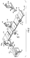
- FIG. 3 and 4 illustrate front and end elevational views, respectively, of a work station 60 adapted to unload electronic components from a flexible tape carrier packaging assembly.
- the elements of the work station now will be described in terms of their functions performed during the tape carrier unloading operation.
- Tape carrier 10 which contains components 12, is supplied from a source 62 such as a box or a reel.
- the tape carrier is advanced through the work station in direction 26 which, in Figure 4, is from left to right as shown, and which would be pointing directly out of the view of Figure 3.
- a drive roller 64 and an idler roller 66 advance the tape carrier through the machine and across a tape carrier bed 68, whereby the empty tape carrier may be collected in a receptacle 70.
- Drive roller 64 is connected to a stepping motor 72 via a coupler 74, which compensates for possible misalignments.
- a knob 76 provides for manual advancement of the tape carrier during initial set-up of the work station.
- a controller 80 interfaces and controls stepping motor 72, shuttle mechanism 40, and possibly fixture 52, in response to inputs from a photosensor device 82, as is known in the art.
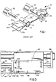
- Figure 5 illustrates an exploded view of shuttle mechanism 40.
- a rodless air cylinder 86 moves the shuttle in direction 48 toward the tape carrier to unload and guide the component into the fixture, and moves the shuttle in direction 54 on its return stroke.
- End plates 88, a guide rod 90, and a shock absorber 92 are used in conjunction with controller 80 to limit the back-and-forth movement of the shuttle.
- Pusher rod 44 is affixed to shuttle base 42 via screws 94.
- Knife structure 46 which will be described in more detail in the following figure, is affixed to shuttle base 42 via a knife clamp 96 and clamp screws 98.
- a V-shaped notch structure 100 is formed by two inwardly-facing knife blade edges.
- knife structure 46 is comprised of two knife blades 102 and 104, which are affixed to shuttle base 42 via knife clamp 96 and clamp screws 98.
- Knife clamp 96 preferably has a bevel 106 on the forward edge to spread apart the tape carrier such that the shuttle may readily pass through the slit.
- Knife blade 102 should be in substantially the same plane and directly adjacent to knife blade 104.
- a bevel 112 on the forward cutting edge of knife blade 102 should be on a single side of the blade, i.e., the blade should not have a two-bevel knife edge.
- a bevel 114 of blade 104 is shown on the reverse side of blade 104, such that there is, for all practical purposes, no gap between blade 102 and blade 104 at notch 100.
- This gapless knife blade bevel configuration is important when plastic tape carriers are used. If even a minor gap exists between blades 102 and 104 at notch 100, the plastic sheet will be caught between the blades, and will buckle, tear and jam the machine.
- Work station 60 dispenses components from tape carrier packaging assembly 10 and guides them into component receiving fixtures 52 in accordance with the following operating steps:
- Controller 80 causes stepping motor 72 to advance tape carrier 10 in direction 26 to position a component-containing cavity on tape carrier bed 68 in line with pusher rod 44.
- Controller 80 causes shuttle 40 to move in direction 54 such that it returns to its original position, ready for the next component dispensing cycle.
- a plastic tape carrier 10 is used to store miniature electrical connectors, having very fragile terminals affixed thereto.
- a connector may measure 3.17 mm (.125 inches) wide by 25.4 mm (1 inch) long by 12.7 mm (.5 inch) high.
- the tape carrier is approximately 101.5 mm (4 inches) wide, and the tubular passageway is open only slightly more than 3.17 mm (.125 inch).
- the wiring harness fixture is located approximately 45.7 cm (18 inches) away from the tape carrier bed.
- Succeeding connectors are spaced approximately 2.5 cm (1 inch) apart along the length of the tape carrier. The machine unloads approximately 300 connectors per hour. Accordingly, it now can be appreciated by those skilled in the art that the present invention solves a significant manufacturing problem, by efficiently and reliably dispensing small, fragile connectors into a distant wiring harness fixture.
- FIG. 7 illustrates an alternate embodiment of knife structure 46.
- a shuttle base 42′ has been constructed to serve the function of upper knife blade 104 of Figure 6.
- a lower blade 120 has a bevel 124 on shuttle base 42′, such that there is no gap between the blades at notch 100.
- FIG 8 shows another embodiment of a knife structure that could be used with the present invention.
- a knife structure 130 is formed from two circular blades 132 and 134, which either freely turn about, or are driven by, center mounting posts 136 and 138, respectively. Again, note that only one side of each circular blade is beveled at 140 and 142, such that no gap exists between the blades at notch 100. Although the circular blades do not present a V-shaped profile, the precise cutting points of the blades as they engage the "planar" flexible sheet material is V-shaped in a tangential context.
- An alternative embodiment of knife structure 130 would be the combination of upper circular blade 132 of Figure 8 with lower blade 120 of Figure 7. Other dual-blade knife configurations are possible.
- a method and apparatus for dispensing components from a flexible tape carrier packaging assembly has been shown and described herein.
- one wall of the container cavity is opened by slitting the tape carrier with a dual-blade knife structure, such that the component-ejecting shuttle mechanism can pass through the cavity.
- the knife structure is comprised of two knife blades constructed and arranged such that a V-shaped notch structure slits the flexible tape carrier without causing it to buckle or tear.
- any type of flexible or inflexible component carrier packaging may be used with the unloading technique described herein.
- the knife blade structure of the present invention also could be used to pierce and open an enclosed pocket of a tape carrier, such that a vacuum-operated pick-and-place machine could remove a chip component.
- different types of knife blades, notch structures, or bevel configurations may be used to achieve the same goal of cutting one or more sheets of the tape carrier without buckling or tearing. All such modifications which retain the basic underlying principles claimed herein are within the scope of this invention.
Landscapes
- Engineering & Computer Science (AREA)
- Manufacturing & Machinery (AREA)
- Packages (AREA)
- Supply And Installment Of Electrical Components (AREA)
- Packaging Frangible Articles (AREA)
Claims (19)
- Appareil de distribution de composants (12) à partir d'un ensemble formant emballage (10) ayant plusieurs cavités (14) contenant un composant, ledit appareil comportant:des moyens formant actionneur (40) destinés à éjecter ledit composant à partir de sa cavité (14), et, reliés aux moyens formant actionneur (40), des moyens formant tige (44) agencés pour pousser ledit composant au moins partiellement en dehors de ladite cavité (14) contenant un composant et des moyens formant couteau (46) destinés à découper au moins un côté de ladite cavité (14) lorsque ledit composant (12) est éjecté, caractérisé en ce que lesdits moyens formant couteau (46) ont une structure d'encoche (100) formée par au moins deux bords de couteau opposés (112, 114), de sorte que lesdits moyens formant couteau (46) découpent ledit ensemble formant emballage (10) au niveau de ladite structure d'encoche (100) pendant l'opération de distribution du composant, les moyens formant tige (44) étant agencés pour pousser ledit composant (12) au moins partiellement en dehors de ladite cavité (14) contenant un composant avant que ladite cavité (14) ne soit découpée par lesdits moyens formant couteau (46).
- Appareil de distribution de composant selon la revendication 1, dans lequel ledit ensemble formant emballage (10) comprend un transporteur à bande souple (18, 19).
- Appareil de distribution de composant selon la revendication 2, dans lequel ledit transporteur à bande souple (18, 19) est réalisé à l'aide de feuilles en matière plastique.
- Appareil de distribution de composant selon l'une quelconque des revendications précédentes, dans lequel lesdites cavités (14) contenant un composant sont construites sous forme d'un passage analogue à un tube à extrémités ouvertes.
- Appareil de distribution de composant selon l'une quelconque des revendications précédentes, comportant en outre des moyens d'entraînement (36, 38) destinés à faire avancer ledit ensemble formant emballage dans une première direction (26) jusqu'à ce qu'une cavité particulière (14) contenant un composant soit positionnée à un emplacement voulu.
- Appareil de distribution de composant selon la revendication 5, dans lequel lesdits moyens formant actionneur (40) comportent des moyens (44) destinés à éjecter ledit composant dans une seconde direction (48) à peu près perpendiculaire à ladite première direction (26).
- Appareil de distribution de composant selon l'une quelconque des revendications précédentes, dans lequel lesdits moyens formant couteau (46) comportent deux lames de couteau (102, 104) fixées à peu près dans le même plan et agencées de telle sorte qu'une structure d'encoche en forme de V (100) soit formée par deux bords (112, 114) de couteau étant intérieurement en vis à vis.
- Appareil de distribution de composant selon la revendication 7, dans lequel chacune desdites deux lames de couteau (102, 104) a un bord à un seul biseau (112, 114), chaque bord biseauté étant dirigé en s'éloignant de l'autre lame de couteau de telle sorte qu'il n'existe pas d'espace entre les deux bords de lame de couteau au niveau de ladite encoche en forme de V (100).
- Appareil de distribution de composant selon l'une quelconque des revendications 1 à 6, dans lequel lesdits moyens formant couteau (130) comportent deux lames de couteau (120, 132), dont au moins une est construite sous forme d'un disque circulaire (132), lesdites lames de couteau étant fixées à peu près dans le même plan et agencées de telle sorte qu'une structure d'encoche en forme de V (100) est formée au niveau de leurs bords de lame se recouvrant.
- Appareil de distribution d'un composant selon l'une quelconque des revendications précédentes, dans lequel la longueur desdits moyens formant tige (44) est inférieure au double de la longueur desdites cavités (14) contenant un composant.
- Appareil de distribution de composant selon l'une quelconque des revendications précédentes, qui comporte en outre des moyens formant accessoire (52), destinés à recevoir ledit composant (12) après qu'il ait été distribué à partir dudit ensemble formant emballage (10).
- Appareil de distribution de composant selon la revendication 11, dans lequel lesdits moyens formant accessoire (52) sont situés au moins à 30 cm (12 pouces) dudit ensemble formant emballage (10) pendant l'opération de distribution.
- Procédé de distribution d'un composant (12) à partir d'un ensemble (10) formant emballage de transporteur à bande souple ayant plusieurs cavités (14) contenant un composant, chaque cavité ayant au moins une paroi latérale souple (18), comportant les étapes consistant à(a) faire avancer ledit transporteur à bande (10) dans une première direction (26) jusqu'à ce qu'une cavité (14) contenant un composant particulier soit adjacente à un élément formant navette (40) ayant des dimensions plus importantes que ledit composant (12); le procédé étant caractérisé en ce qu'il comporte les étapes consistant à(b) éjecter ledit composant (12) au moins partiellement de sa cavité (14); et, de manière subséquente,(c) ouvrir ladite paroi latérale souple (18'), par découpe dudit transporteur à bande (10) en utilisant des moyens formant couteau (102, 104) et continuer à éjecter ledit composant en faisant passer au moins une partie dudit élément formant navette (40) à travers l'ouverture (50) de la paroi latérale souple (18').
- Procédé selon la revendication 13, comportant l'étape consistant à guider ledit composant (12) jusqu'à l'intérieur d'un accessoire de réception de composant (52) .
- Procédé selon la revendication 13, dans lequel les cavités (14) contenant un composant sont construites sous forme d'un passage analogue à un tube ayant au moins une extrémité ouverte, et comportant l'étape consistant à positionner un bord de ladite paroi latérale souple (18') de la cavité situé au niveau de ladite extrémité ouverte à l'intérieur d'une structure d'encoche (100) formée par au moins deux lames de couteau étant intérieurement en vis à vis.
- Poste de travail (60) adapté pour décharger des composants électroniques (12) à partir d'un ensemble (10) formant emballage de transporteur à bande souple jusqu'à l'intérieur d'un accessoire (52) de réception de composant, ledit ensemble formant emballage ayant plusieurs passages tubulaires (14) espacés contenant un composant, à extrémités ouvertes, ledit poste de travail comportant:des moyens d'entraînement (64, 66, 72, 74) destinés à faire avancer ledit ensemble formant emballage dans une première direction (26) jusqu'à ce qu'un passage tubulaire (14) contenant un composant particulier soit positionné au niveau d'un emplacement voulu;des moyens formant navette (40) destinés à décharger ledit composant (12) à partir dudit ensemble formant emballage (10), et destinés à guider ledit composant (12) jusqu'à l'intérieur dudit accessoire (52) de réception d'un composant, comportant des moyens formant tige (44) destinés à pousser ledit composant (12) en dehors dudit passage tubulaire (14) et jusqu'à l'intérieur dudit accessoire (52) de réception d'un composant, et des moyens formant couteau (46) destinés à découper au moins un côté dudit passage tubulaire (14) lorsque lesdits moyens formant tige (44) poussent ledit composant (12) en dehors dudit passage tubulaire (14), caractérisé en ce que lesdits moyens formant couteau (46) comportent deux lames de couteau (102, 104) fixées à peu près dans le même plan et agencées de telle sorte qu'une structure d'encoche en forme de V (100) soit formée par deux bords (112, 114) de couteau de celles-ci intérieurement en vis à vis et en ce que les moyens formant tige (44) sont agencés pour pousser ledit composant au moins partiellement en dehors de ladite cavité (14) contenant un composant avant que ladite cavité (14) ne soit découpée, etdes moyens de commande (80) destinés à activer lesdits moyens formant navette (40) et lesdits moyens d'entraînement (64, 66, 72, 74) de telle sorte qu'ils coopèrent pour décharger chaque composant (12) à partir dudit ensemble formant emballage (10) en positionnant et en découpant ledit transporteur souple (18) au niveau de ladite structure d'encoche (100) sans entraîner ledit transporteur souple (18') à se gondoler.
- Poste de travail selon la revendication 16, dans lequel chacune desdites deux lames de couteau (102, 104) a un bord à un seul biseau (112, 114), chaque bord biseauté étant dirigé en s'éloignant de l'autre lame de couteau de telle sorte qu'il n'existe pas d'espace entre les deux bords de lame de couteau au niveau de ladite encoche en forme de V (100).
- Poste de travail selon l'une quelconque des revendications 15 à 17, dans lequel ledit accessoire (52) de réception d'un composant est situé à au moins 30 cm (12 pouces) dudit emplacement voulu, et dans lequel la longueur desdits moyens formant tige (44) est inférieure à 15 cm (6 pouces).
- Poste de travail selon l'une quelconque des revendications 15 à 18, dans lequel lesdits composants électroniques (12) sont des connecteurs électriques ayant des bornes fragiles fixées sur ceux-ci, et dans lequel ledit accessoire (52) de réception d'un composant est une partie d'une machine d'emboîtement de fils.
Applications Claiming Priority (2)
| Application Number | Priority Date | Filing Date | Title |
|---|---|---|---|
| US471996 | 1990-01-24 | ||
| US07/471,996 US5017078A (en) | 1990-01-24 | 1990-01-24 | Method and apparatus for unloading components from tape carrier packaging |
Publications (3)
| Publication Number | Publication Date |
|---|---|
| EP0439348A2 EP0439348A2 (fr) | 1991-07-31 |
| EP0439348A3 EP0439348A3 (en) | 1992-04-29 |
| EP0439348B1 true EP0439348B1 (fr) | 1996-03-20 |
Family
ID=23873804
Family Applications (1)
| Application Number | Title | Priority Date | Filing Date |
|---|---|---|---|
| EP91300529A Expired - Lifetime EP0439348B1 (fr) | 1990-01-24 | 1991-01-24 | Procédé et appareil pour décharger des composants empaquetés sur une bande de transport |
Country Status (4)
| Country | Link |
|---|---|
| US (1) | US5017078A (fr) |
| EP (1) | EP0439348B1 (fr) |
| JP (1) | JPH07109953B2 (fr) |
| DE (1) | DE69117991T2 (fr) |
Families Citing this family (7)
| Publication number | Priority date | Publication date | Assignee | Title |
|---|---|---|---|---|
| US5605430A (en) * | 1994-02-15 | 1997-02-25 | Zierick Manufacturing Corporation | Feeder and method of supplying a continuous strip of surface mount contacts to surface mounting equipment |
| US5449265A (en) * | 1994-02-15 | 1995-09-12 | Zierick Manufacturing Corporation | Feeder and method of supplying a continuous strip of surface mount contacts to pick-and-place machine |
| DE19714965C1 (de) * | 1997-04-10 | 1998-06-18 | Connectool Gmbh & Co | Schneidvorrichtung für gegurtete elektrische Kontakte |
| US6162007A (en) * | 1999-01-14 | 2000-12-19 | Witte; Stefan | Apparatus for feeding electronic component tape |
| US6691859B2 (en) * | 2001-12-20 | 2004-02-17 | Autosplice Systems, Inc. | Automatic feeder for strip-supported contacts |
| CN221189469U (zh) | 2023-11-09 | 2024-06-21 | 贺娟 | 一种破开密封包装的打孔装置 |
| WO2025117792A2 (fr) * | 2023-11-28 | 2025-06-05 | Amgen Inc. | Systèmes et procédés automatisés pour composants d'emballage sous film |
Family Cites Families (23)
| Publication number | Priority date | Publication date | Assignee | Title |
|---|---|---|---|---|
| DE957717C (de) * | 1957-01-17 | Kerb-Konus-Gesellschaft Dr. Carl Eibes & Co., Schnaittenbach (Obpf.) und Mahle Kommanditgesellschaft, Stuttgart - Bad Cannstatt | Zubringereinrichtung für stiftförmige Verbindungsteile | |
| US2576492A (en) * | 1947-05-05 | 1951-11-27 | Frank J Vogel | Bag slitter |
| US3496973A (en) * | 1967-04-12 | 1970-02-24 | Robert L Ballard | Cutting tool edge construction |
| US3487965A (en) * | 1968-05-17 | 1970-01-06 | Nat Can Corp | Device and method of dispensing container contents |
| US3590481A (en) * | 1969-01-17 | 1971-07-06 | Amp Inc | Method and means for facilitating rapid termination of coaxial connectors |
| US4438559A (en) * | 1980-06-27 | 1984-03-27 | Fuji Machine Mfg. Co. Ltd. | Apparatus for automatically mounting non-lead electronic components on printed-circuit |
| US4428709A (en) * | 1980-11-28 | 1984-01-31 | Automation International Corp. | De-packaging apparatus |
| JPS60107900A (ja) * | 1983-11-16 | 1985-06-13 | ソニー株式会社 | 電子部品装着装置 |
| US4617733A (en) * | 1984-04-06 | 1986-10-21 | Molex Incorporated | Process of manufacturing a flexible substrate assembly |
| US4583641A (en) * | 1984-09-20 | 1986-04-22 | Gelzer John R | Article packaging system |
| US4621486A (en) * | 1984-11-15 | 1986-11-11 | Molex Incorporated | Apparatus for making a tape carrier |
| US4631897A (en) * | 1984-11-15 | 1986-12-30 | Donald Slavicek | Method of making a tape carrier |
| US4736841A (en) * | 1985-02-20 | 1988-04-12 | Murata Manufacturing Co., Ltd. | Electronic component series |
| JPS61217456A (ja) * | 1985-03-20 | 1986-09-27 | Matsushita Electric Ind Co Ltd | テ−ピングカセツト式電子部品の送り装置 |
| GB8513296D0 (en) * | 1985-05-28 | 1985-07-03 | Dynapert Precima Ltd | Machines for handling electrical components |
| JPS62111825A (ja) * | 1985-11-06 | 1987-05-22 | Fuji Kikai Seizo Kk | キヤリヤテ−プから電子部品を取り出す方法 |
| NL8503063A (nl) * | 1985-11-08 | 1987-06-01 | Philips Nv | Bandverpakking voor elektrische en/of elektronische onderdelen. |
| US4735341A (en) * | 1986-05-12 | 1988-04-05 | Universal Instruments Corporation | Feeder for electrical component supply tapes |
| US4718160A (en) * | 1986-07-10 | 1988-01-12 | Panduit Corp. | Terminal strip applicator |
| JP2662948B2 (ja) * | 1986-10-30 | 1997-10-15 | ニツト− システム テクノロジ− インコ−ポレ−テツド | チップテープのトップテープ除去装置 |
| US4763780A (en) * | 1987-03-24 | 1988-08-16 | E. I. Du Pont De Nemours And Company | Package and apparatus for dispensing electrical connectors |
| SE464575B (sv) * | 1987-07-13 | 1991-05-13 | Skf Ab | Saett och anordning foer att toemma ett foerpackningsband |
| JPH0346957Y2 (fr) * | 1988-09-05 | 1991-10-04 |
-
1990
- 1990-01-24 US US07/471,996 patent/US5017078A/en not_active Expired - Lifetime
-
1991
- 1991-01-23 JP JP3022890A patent/JPH07109953B2/ja not_active Expired - Fee Related
- 1991-01-24 EP EP91300529A patent/EP0439348B1/fr not_active Expired - Lifetime
- 1991-01-24 DE DE69117991T patent/DE69117991T2/de not_active Expired - Fee Related
Also Published As
| Publication number | Publication date |
|---|---|
| EP0439348A2 (fr) | 1991-07-31 |
| JPH07109953B2 (ja) | 1995-11-22 |
| US5017078A (en) | 1991-05-21 |
| DE69117991T2 (de) | 1996-10-31 |
| JPH04212499A (ja) | 1992-08-04 |
| DE69117991D1 (de) | 1996-04-25 |
| EP0439348A3 (en) | 1992-04-29 |
Similar Documents
| Publication | Publication Date | Title |
|---|---|---|
| EP0934220B1 (fr) | Appareil ameliore pour la distribution d'attaches de cable | |
| US3368428A (en) | Wire cutting and stripping machine | |
| US4718157A (en) | Method and an apparatus for debanding | |
| JPH0157519B2 (fr) | ||
| US5017078A (en) | Method and apparatus for unloading components from tape carrier packaging | |
| US4313251A (en) | System for applying electronic components to a circuit board | |
| US4687152A (en) | Machines for handling electrical components | |
| US4177554A (en) | Assembling leads to a substrate | |
| US6584677B2 (en) | High-speed, high-capacity twist pin connector fabricating machine and method | |
| US4043032A (en) | Terminal applicator apparatus for terminals in strip form | |
| CA1240412A (fr) | Mecanisme de manutention de composants electroniques | |
| US20020108934A1 (en) | Pneumatic inductor and method of electrical connector delivery and organization | |
| JP2005170498A (ja) | 結束帯切断装置 | |
| GB2036611A (en) | Inserting terminals into a printed circuit board | |
| JP2000317722A (ja) | カッタ装置 | |
| US4650391A (en) | Electrical connector pick-up station | |
| EP1066742B1 (fr) | Dispositif de separation servant a separer un premier composant d'une rangee de composants | |
| CN217071052U (zh) | 开关自动剥线焊接设备 | |
| US5727305A (en) | Programmable pin feeder | |
| JP2621353B2 (ja) | 電子部品挿入方法及びその装置及び電子部品保持装置 | |
| EP0607705B1 (fr) | Procédé et appareil pour enrubanner de nouveau des composants électroniques | |
| CN221018415U (zh) | 一种线束折弯机 | |
| EP0182504A2 (fr) | Assemblage d'un support flexible et de composants solides et méthodes et appareil pour réaliser et traiter celui-ci | |
| US20030110619A1 (en) | Electrical connector wire trim and press apparatus | |
| JP2003187943A (ja) | 端子供給装置及びそれを用いた端子実装装置 |
Legal Events
| Date | Code | Title | Description |
|---|---|---|---|
| PUAI | Public reference made under article 153(3) epc to a published international application that has entered the european phase |
Free format text: ORIGINAL CODE: 0009012 |
|
| AK | Designated contracting states |
Kind code of ref document: A2 Designated state(s): DE FR GB IT NL |
|
| PUAL | Search report despatched |
Free format text: ORIGINAL CODE: 0009013 |
|
| AK | Designated contracting states |
Kind code of ref document: A3 Designated state(s): DE FR GB IT NL |
|
| RIN1 | Information on inventor provided before grant (corrected) |
Inventor name: ERKLIN, ROBERT E.SR Inventor name: WEST, BERNARD M. Inventor name: INGWERSEN, PETER |
|
| 17P | Request for examination filed |
Effective date: 19920928 |
|
| 17Q | First examination report despatched |
Effective date: 19940210 |
|
| GRAA | (expected) grant |
Free format text: ORIGINAL CODE: 0009210 |
|
| ITF | It: translation for a ep patent filed | ||
| AK | Designated contracting states |
Kind code of ref document: B1 Designated state(s): DE FR GB IT NL |
|
| REF | Corresponds to: |
Ref document number: 69117991 Country of ref document: DE Date of ref document: 19960425 |
|
| ET | Fr: translation filed | ||
| PLBE | No opposition filed within time limit |
Free format text: ORIGINAL CODE: 0009261 |
|
| STAA | Information on the status of an ep patent application or granted ep patent |
Free format text: STATUS: NO OPPOSITION FILED WITHIN TIME LIMIT |
|
| 26N | No opposition filed | ||
| REG | Reference to a national code |
Ref country code: GB Ref legal event code: IF02 |
|
| PGFP | Annual fee paid to national office [announced via postgrant information from national office to epo] |
Ref country code: GB Payment date: 20041210 Year of fee payment: 15 |
|
| PGFP | Annual fee paid to national office [announced via postgrant information from national office to epo] |
Ref country code: NL Payment date: 20041215 Year of fee payment: 15 |
|
| PGFP | Annual fee paid to national office [announced via postgrant information from national office to epo] |
Ref country code: FR Payment date: 20050105 Year of fee payment: 15 |
|
| PGFP | Annual fee paid to national office [announced via postgrant information from national office to epo] |
Ref country code: DE Payment date: 20050131 Year of fee payment: 15 |
|
| PG25 | Lapsed in a contracting state [announced via postgrant information from national office to epo] |
Ref country code: GB Free format text: LAPSE BECAUSE OF NON-PAYMENT OF DUE FEES Effective date: 20060124 |
|
| PG25 | Lapsed in a contracting state [announced via postgrant information from national office to epo] |
Ref country code: FR Free format text: LAPSE BECAUSE OF NON-PAYMENT OF DUE FEES Effective date: 20060131 |
|
| PGFP | Annual fee paid to national office [announced via postgrant information from national office to epo] |
Ref country code: IT Payment date: 20060131 Year of fee payment: 16 |
|
| PG25 | Lapsed in a contracting state [announced via postgrant information from national office to epo] |
Ref country code: NL Free format text: LAPSE BECAUSE OF NON-PAYMENT OF DUE FEES Effective date: 20060801 Ref country code: DE Free format text: LAPSE BECAUSE OF NON-PAYMENT OF DUE FEES Effective date: 20060801 |
|
| GBPC | Gb: european patent ceased through non-payment of renewal fee |
Effective date: 20060124 |
|
| NLV4 | Nl: lapsed or anulled due to non-payment of the annual fee |
Effective date: 20060801 |
|
| REG | Reference to a national code |
Ref country code: FR Ref legal event code: ST Effective date: 20060929 |
|
| PG25 | Lapsed in a contracting state [announced via postgrant information from national office to epo] |
Ref country code: IT Free format text: LAPSE BECAUSE OF NON-PAYMENT OF DUE FEES Effective date: 20070124 |