EP0439509B1 - VERFAHREN ZUM CRACKEN VON RAFFINIERUNGSRüCKSTäNDEN - Google Patents
VERFAHREN ZUM CRACKEN VON RAFFINIERUNGSRüCKSTäNDEN Download PDFInfo
- Publication number
- EP0439509B1 EP0439509B1 EP89912019A EP89912019A EP0439509B1 EP 0439509 B1 EP0439509 B1 EP 0439509B1 EP 89912019 A EP89912019 A EP 89912019A EP 89912019 A EP89912019 A EP 89912019A EP 0439509 B1 EP0439509 B1 EP 0439509B1
- Authority
- EP
- European Patent Office
- Prior art keywords
- additive
- catalyst
- dense bed
- cracking catalyst
- regenerator
- Prior art date
- Legal status (The legal status is an assumption and is not a legal conclusion. Google has not performed a legal analysis and makes no representation as to the accuracy of the status listed.)
- Expired - Lifetime
Links
- 238000000034 method Methods 0.000 title claims abstract description 20
- 238000005336 cracking Methods 0.000 title claims description 27
- 239000003054 catalyst Substances 0.000 claims abstract description 107
- 239000000654 additive Substances 0.000 claims abstract description 61
- 230000000996 additive effect Effects 0.000 claims abstract description 60
- 239000007789 gas Substances 0.000 claims abstract description 14
- 239000000571 coke Substances 0.000 claims abstract description 13
- 238000004523 catalytic cracking Methods 0.000 claims abstract description 10
- 239000000203 mixture Substances 0.000 claims abstract description 9
- 230000001172 regenerating effect Effects 0.000 claims abstract description 7
- 230000008929 regeneration Effects 0.000 claims abstract description 6
- 238000011069 regeneration method Methods 0.000 claims abstract description 6
- 229910052751 metal Inorganic materials 0.000 claims description 15
- 239000002184 metal Substances 0.000 claims description 15
- 238000002485 combustion reaction Methods 0.000 claims description 13
- 150000002739 metals Chemical class 0.000 claims description 13
- 239000002245 particle Substances 0.000 claims description 11
- QVGXLLKOCUKJST-UHFFFAOYSA-N atomic oxygen Chemical compound [O] QVGXLLKOCUKJST-UHFFFAOYSA-N 0.000 claims description 10
- 239000001301 oxygen Substances 0.000 claims description 10
- 229910052760 oxygen Inorganic materials 0.000 claims description 10
- 239000000463 material Substances 0.000 claims description 8
- 229930195733 hydrocarbon Natural products 0.000 claims description 6
- 150000002430 hydrocarbons Chemical class 0.000 claims description 6
- 238000004064 recycling Methods 0.000 claims description 4
- 238000000926 separation method Methods 0.000 claims description 3
- 238000005235 decoking Methods 0.000 claims description 2
- UGFAIRIUMAVXCW-UHFFFAOYSA-N Carbon monoxide Chemical compound [O+]#[C-] UGFAIRIUMAVXCW-UHFFFAOYSA-N 0.000 abstract description 8
- 239000003546 flue gas Substances 0.000 abstract description 3
- 229910052720 vanadium Inorganic materials 0.000 description 9
- LEONUFNNVUYDNQ-UHFFFAOYSA-N vanadium atom Chemical compound [V] LEONUFNNVUYDNQ-UHFFFAOYSA-N 0.000 description 9
- 239000003921 oil Substances 0.000 description 7
- PXHVJJICTQNCMI-UHFFFAOYSA-N Nickel Chemical compound [Ni] PXHVJJICTQNCMI-UHFFFAOYSA-N 0.000 description 6
- XLYOFNOQVPJJNP-UHFFFAOYSA-N water Substances O XLYOFNOQVPJJNP-UHFFFAOYSA-N 0.000 description 6
- 229910002091 carbon monoxide Inorganic materials 0.000 description 5
- 239000004215 Carbon black (E152) Substances 0.000 description 3
- UFHFLCQGNIYNRP-UHFFFAOYSA-N Hydrogen Chemical compound [H][H] UFHFLCQGNIYNRP-UHFFFAOYSA-N 0.000 description 3
- 238000006243 chemical reaction Methods 0.000 description 3
- 238000004939 coking Methods 0.000 description 3
- 239000000945 filler Substances 0.000 description 3
- 239000001257 hydrogen Substances 0.000 description 3
- 229910052739 hydrogen Inorganic materials 0.000 description 3
- 229910052759 nickel Inorganic materials 0.000 description 3
- BASFCYQUMIYNBI-UHFFFAOYSA-N platinum Chemical compound [Pt] BASFCYQUMIYNBI-UHFFFAOYSA-N 0.000 description 3
- 238000012545 processing Methods 0.000 description 3
- 238000010791 quenching Methods 0.000 description 3
- 239000000243 solution Substances 0.000 description 3
- OKTJSMMVPCPJKN-UHFFFAOYSA-N Carbon Chemical compound [C] OKTJSMMVPCPJKN-UHFFFAOYSA-N 0.000 description 2
- CURLTUGMZLYLDI-UHFFFAOYSA-N Carbon dioxide Chemical compound O=C=O CURLTUGMZLYLDI-UHFFFAOYSA-N 0.000 description 2
- PNEYBMLMFCGWSK-UHFFFAOYSA-N aluminium oxide Inorganic materials [O-2].[O-2].[O-2].[Al+3].[Al+3] PNEYBMLMFCGWSK-UHFFFAOYSA-N 0.000 description 2
- 238000013459 approach Methods 0.000 description 2
- 230000015572 biosynthetic process Effects 0.000 description 2
- 229910052799 carbon Inorganic materials 0.000 description 2
- HNPSIPDUKPIQMN-UHFFFAOYSA-N dioxosilane;oxo(oxoalumanyloxy)alumane Chemical group O=[Si]=O.O=[Al]O[Al]=O HNPSIPDUKPIQMN-UHFFFAOYSA-N 0.000 description 2
- 230000009977 dual effect Effects 0.000 description 2
- 230000000694 effects Effects 0.000 description 2
- 230000001965 increasing effect Effects 0.000 description 2
- 238000002161 passivation Methods 0.000 description 2
- 231100000572 poisoning Toxicity 0.000 description 2
- 230000000607 poisoning effect Effects 0.000 description 2
- 150000003682 vanadium compounds Chemical class 0.000 description 2
- 239000010457 zeolite Substances 0.000 description 2
- 229910021536 Zeolite Inorganic materials 0.000 description 1
- 239000002253 acid Substances 0.000 description 1
- 229910052787 antimony Inorganic materials 0.000 description 1
- WATWJIUSRGPENY-UHFFFAOYSA-N antimony atom Chemical compound [Sb] WATWJIUSRGPENY-UHFFFAOYSA-N 0.000 description 1
- 229910002092 carbon dioxide Inorganic materials 0.000 description 1
- 239000001569 carbon dioxide Substances 0.000 description 1
- 230000003197 catalytic effect Effects 0.000 description 1
- 238000006555 catalytic reaction Methods 0.000 description 1
- 150000001875 compounds Chemical class 0.000 description 1
- 238000011109 contamination Methods 0.000 description 1
- 230000008021 deposition Effects 0.000 description 1
- 230000003028 elevating effect Effects 0.000 description 1
- 239000012530 fluid Substances 0.000 description 1
- 239000010763 heavy fuel oil Substances 0.000 description 1
- 238000002347 injection Methods 0.000 description 1
- 239000007924 injection Substances 0.000 description 1
- 239000007788 liquid Substances 0.000 description 1
- 238000012986 modification Methods 0.000 description 1
- 230000004048 modification Effects 0.000 description 1
- 230000003647 oxidation Effects 0.000 description 1
- 238000007254 oxidation reaction Methods 0.000 description 1
- 230000001590 oxidative effect Effects 0.000 description 1
- 229910052697 platinum Inorganic materials 0.000 description 1
- 239000002574 poison Substances 0.000 description 1
- 231100000614 poison Toxicity 0.000 description 1
- 125000003367 polycyclic group Chemical group 0.000 description 1
- 239000011148 porous material Substances 0.000 description 1
- 239000002243 precursor Substances 0.000 description 1
- 238000011084 recovery Methods 0.000 description 1
- 125000006850 spacer group Chemical group 0.000 description 1
- 238000004227 thermal cracking Methods 0.000 description 1
- -1 vanadic acid Chemical class 0.000 description 1
- WQEVDHBJGNOKKO-UHFFFAOYSA-K vanadic acid Chemical compound O[V](O)(O)=O WQEVDHBJGNOKKO-UHFFFAOYSA-K 0.000 description 1
- 230000008016 vaporization Effects 0.000 description 1
Images

Classifications
-
- C—CHEMISTRY; METALLURGY
- C10—PETROLEUM, GAS OR COKE INDUSTRIES; TECHNICAL GASES CONTAINING CARBON MONOXIDE; FUELS; LUBRICANTS; PEAT
- C10G—CRACKING HYDROCARBON OILS; PRODUCTION OF LIQUID HYDROCARBON MIXTURES, e.g. BY DESTRUCTIVE HYDROGENATION, OLIGOMERISATION, POLYMERISATION; RECOVERY OF HYDROCARBON OILS FROM OIL-SHALE, OIL-SAND, OR GASES; REFINING MIXTURES MAINLY CONSISTING OF HYDROCARBONS; REFORMING OF NAPHTHA; MINERAL WAXES
- C10G11/00—Catalytic cracking, in the absence of hydrogen, of hydrocarbon oils
- C10G11/14—Catalytic cracking, in the absence of hydrogen, of hydrocarbon oils with preheated moving solid catalysts
- C10G11/18—Catalytic cracking, in the absence of hydrogen, of hydrocarbon oils with preheated moving solid catalysts according to the "fluidised-bed" technique
- C10G11/182—Regeneration
Definitions
- the fluidized catalytic cracking process is a mature process. It is used to convert relatively heavy, usually distillable, feeds to more valuable lighter products. There is an increasing need in modem refineries to convert more of the "bottom of the barrel to more valuable lighter products, e.g., resids or residual oil fractions.
- Residual oils have a large percentage of refractor components such as polycyclic aromatics which are difficult to crack. Resids also contain large amounts of metals which rapidly deactivate conventional catalysts.
- Some attempts at catalytic processing of these stocks have been made e.g., adding relatively small amounts of residual oil to conventional FCC feed. FCC units can tolerate modest amounts of resids in the feed, e.g., 5 to 10 weight percent but the heavy feeds increase the burning load on the regenerator (because of their high Conradson carbon content) and poison the catalyst, with nickel and vanadium. Limiting the amount of resid in the FCC feed has been the method of choice in controlling regeneration operation although consideration has been given to adding catalyst coolers.
- the nickel and vanadium contamination problem can be overcome to some extent by practicing metals passivation, e.g., addition of antimony to the unit to passivate the metals added with the feed.
- Metals passivation has allowed FCC units to continue operating with catalyst containing relatively high amounts of nickel and vanadium, but has not been a complete solution.
- the vanadium seems to attack the zeolite structure of modern FCC catalysts, resulting in rapid loss of catalyst activity.
- the exact cause of vanadium poisoning is not completely understood, but it is believed that oxidized vanadium compounds are formed in the highly oxidizing atmosphere of conventional FCC regenerators and these compounds, particularly vanadic acid, rapidly attack the zeolite.
- the problem is discussed in Vanadium poisoning of Cracking Catalyst, Wormsbecher et al, Journal of Catalysis , 100, 130-137 (1986).
- the coarse catalyst is regenerated in a single stage, under relatively mild conditions which minimize oxidation of vanadium compounds on the catalyst but which still remove much of the hydrogen content of the coke and eliminate most of the water precursors.
- the conventional FCC catalyst is regenerated to some extent in the first stage regenerator and then undergoes a second stage of regeneration at a higher temperature, with higher oxygen concentrations. Use of two different kinds of catalyst in a two stage regenerator, permits significantly higher metals levels to be tolerated in the feed.
- the present invention provides a fluidized catalytic cracking process wherein a heavy, metals laden feed contacts hot regenerated catalytic cracking catalyst in a riser reactor, the feed is cracked to lighter products and the cracking catalyst is coked, catalyst is separated from cracked products in a separation means, coked catalyst is stripped of strippable hydrocarbons with a stripping gas, the stripped catalyst is regenerated with an oxygen-containing gas in a regeneration zone, and the regenerated catalyst is recycled to the riser to contact more heavy feed characterized by:
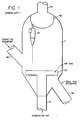
- Figure I represents a prior art FCC regenerator using a single dense bed.
- FCC regenerator 1 receives spent catalyst from the FCC unit via line 40. Combustion air is added via line 10 and air grid 20. The air burns coke from the catalyst. Hot regenerated catalyst is removed via line 30 for reuse in the FCC reactor. Flue gas formed during coke combustion is discharged via cyclone 50 (which recovers the entrained FCC catalyst), plenum chamber 60 and outlet 70.
- FIG II which represents one preferred embodiment of the present invention, shows a revamped FCC regenerator 1 (the outer shell of the regenerator can be identical to that of the prior art regenerator, so identical elements have the same numbers in Figures I and II).
- a mixture of spent catalyst and coked heavy, vanadium-getter additive is added to the regenerator via line 40.
- the relatively heavy, or larger, vanadium getter additive sinks to the bottom of the regenerator 1 because the additive settles faster than the conventional FCC catalyst.
- the getter additive is decoked in the base of the regenerator by the addition of secondary air via line 210 and distributor ring 220 in the very base of the regenerator.
- the getter additive is decoked to some extent but preferably still contains some coke, e.g.
- Temperatures tend to be extremely high in the regenerator of the present invention, primarily because of the increased burning duty forced upon the regenerator by the processing of heavy, residual feeds containing large amount of Conradson carbon and similar materials.
- the additive is preheated to some extent in passing through the dense bed of conventional catalyst 260 in its descent to the base region 250 of the FCC regenerator.
- the conventional catalyst is regenerated in dense bed 260, primarily with primary combustion air added via inlet 110 and primary air ring 120. Regenerated catalyst is withdrawn via line 130 and discharged to the FCC riser reactor, preferably at an intermediate point thereof.
- steam coils 270 are preferably present in the lower region 250. Catalyst may be added to or removed from region 250 to a cooler or heat exchanger (not shown) via line 330.
- Filler or spacers 220 are shown to better define the lower region 250 and separate it from the upper region 260 wherein relatively lighter catayst is segregated.
- the fillers or inserts 220 provide a relatively large change in superficial vapor velocity within the regenerator, which improves the separation, by elutriation, of relatively fast settling getter additive from the more readily fluidizable conventional FCC catalyst.
- the decoked getter additive will have a longer residence time than the conventional catalyst. This is because the decoked additive will have much higher settling velocity, preferably a settling velocity which is 50-100 percent of the superficial vapor velocity at the base of the riser reactor.
- the base of the riser reactor may be broadened (to decrease the superficial vapor velocity and provide for additional contact time of the getter additive with the fresh feed) or straight. It is also within the scope of the present invention to have split feed to the FCC riser reactor. If split feed injection is practiced, preferably the feed with the most metals content, and highest CCR content, is added first, to contact the getter additive. The conventional feed and the conventional hot, regenerated FCC catalyst, may then be added to higher portions of the riser.
- At least one method of removing heat from the regenerator It will usually be preferred to have at least one method of removing heat from the regenerator.
- steam coils are shown only in region 250 in Figure II, it is acceptable to have steam coils in the upper section 260 of the dense bed of the regenerator or in the dilute phase region of the regenerator 1.
- Catalyst coolers may also be used to remove heat from decoked particles in line 230 or regenerated catalyst removed via line 130.
- air addition, and consequently coke combustion, along with heat removal from the regenerator is adjusted so that the decoked getter additive is much hotter than the conventional FCC catalyst.
- the high temperature, decoked getter additive will be very efficient at vaporizing heavy, resid-containing feedstocks and rapidly demetallize the crude.
- the conventional cracking catalyst whether added at about the same point as the decoked getter additive, or added higher up in the riser, can be at a somewhat lower temperature, to quench the thermal reactions provoked by the hot, decoked getter additive.
- the system is relatively "fail safe" in that if some conventional catalyst is entrained in the getter additive and passes through region 250 and via line 230 to the base of the riser to contact fresh, resid-containing feed, the conventional catalyst will be protected to some extent from metals deposition by the presence of relatively large amounts of getter additive.
- the conventional FCC catalyst and getter additive will pass together through the FCC riser reactor, conventional stripper, and back into the regenerator, where they will have another chance to be separated.
- getter additive bed 250 If any of the getter additive happens to be swept into the FCC catalyst return line 130, it will simply be swept up the FCC riser reactor, to be eventually segregated with other getter additive in getter additive bed 250.
- getter additive Most of the getter additive, preferably more than 90 percent or more, will pass by elutriation or settling or density differences to the base of the regenerator 1 and be regenerated in a relatively reducing atmosphere. This will minimize the formation of highly oxidized forms of vanadium.
- the decoking of the getter additive in bed 250 will occur in a relatively low moisture zone.
- Most of the water in an FCC regenerator comes from water of combustion (via burning of hydrogen in the hydrocarbonaceous coke) and from stripping steam that is entrained with catalyst entering the regenerator. These two sources of water will be largely removed in the present invention, because essentially all of the stripping steam will be removed as getter additive passes through bed 260. Much, probably a majority, of the hydrogen in the coke will also be burned in the relatively short residence time of getter additive in bed 260 as it passes down to bed 250.
- the process of the present invention is extremely efficient for regenerating catalyst while minimizing emissions of both NO x and carbon monoxide. This is unusual behavior, in that designs which minimize NO x emissions tend to maximize carbon monoxide emissions.
- NO x emissions can be minimized by running the dense bed portion 250 of the regenerator with a relatively reducing atmosphere. This will minimize NO x emissions.
- Much CO will be formed (usually there will be an equimolar mixture of carbon monoxide and carbon dioxide as a result of combustion in bed 250). This would normally result in an intolerable amount of CO emissions, however the carbon monoxide can be completely burned in the dense bed 260 without causing afterburning in the dilute phase portion of regenerator 1.
- the CO can be afterburned both because additional air is added (the primary air added via line 110 and primary air ring 120) and because CO combustion promoter can be present in the system.
- CO combustion promoters such as 0.01 to 50 ppm, preferably 0.5 to 5 wt ppm platinum based on catalyst inventory, added as platinum on alumina, or solutions of chloroplatinic acid added to the circulating catalyst, are well known.
- the process of the present invention permits extremely efficient use of CO combustion promoters, especially of Pt-alumina additives with particle sizes similar to that of conventional FCC catalyst.
- These CO combustion promoters will congregate in bed 260. This permits relatively less accurate addition of secondary air via air inlet 210 and air ring 220. There is no fear of afterburning above dense bed 250 because of poor air distibution or poor control of the amount of air added. All air added via inlet 210 will be consumed in bed 260, both in regenerating the conventional FCC catalyst and in combusting the carbon monoxide formed in base 250.
- NO x emissions are minimized in the present invention because much of the coke combustion occurs in the region 250, characterized by a relatively reducing atmosphere which minimizes NO x formation.
- a hot stripper in addition to the conventional stream stripper, be used intermediate the conventional catalyst stripper and the regenerator of the invention.
- the catalyst stripper can be made hotter by the addition of flue gas or hot regenerated catalyst.
- the use of a hot stripper is preferred because it increases the recovery of valuable liquid hydrocarbon products and reduces the amount of hydrocarbons that are burned in the regenerator.
- the hot stripper also reduces the amount of water of combustion formed in the regenerator.
- the present invention can be easily practiced in many existing single bed regenerators by making the following changes.
- the core section would be filled with a filler such as element 220 of Figure II to decrease its diameter (area) considerably along with elevating the present air grid.
- the present air grid may be made lighter and smaller as it would not take as much air.
- the overflow well would be raised some and would discharge active catalyst to an intermediate point on the riser.
- Some riser modifications will of course be required to accomodate two catalyst feed points.
- Running a higher average bed depth in the regenerator will help accommodate the coarse additive or "getter”.
- a new catalyst circulation line e.g., line 230
- the steam generating coils 270 in the modified conical section are preferably added (or a new catalyst cooler tied in here). A good place to locate the catalyst cooler is in the regenerated catalyst return line, because the particles are easily and smoothly fluidized.
- a new air ring (e.g., ring 220) must be installed in the conical section to take a major portion e.g., 50-90% of the air. This may not be a ring but a "sparger" injecting the air in over a range of depths to separate out fine FCC catalyst from the larger particles more efficiently.
- Catalyst can be conventional FCC catalyst. It may have a particle size, or average diameter of 30-100 microns.
- Additive materials preferably have a high affinity for metals, such as vanadium. Relatively large particles of relatively soft alumina are preferred.
- the additive has an average particle diameter at least 20% larger, and, most preferably 100% larger, than the cracking catalyst and an average bulk density at least 10 percent higher than the cracking catalyst.
- Feeds can be conventional, but the greatest economic returns will be realized when large amounts of resid, asphaltenes, etc. are included, e.g., 10-100% resid feed, exclusive of recycle streams.
Landscapes
- Chemical & Material Sciences (AREA)
- Oil, Petroleum & Natural Gas (AREA)
- Engineering & Computer Science (AREA)
- Chemical Kinetics & Catalysis (AREA)
- General Chemical & Material Sciences (AREA)
- Organic Chemistry (AREA)
- Production Of Liquid Hydrocarbon Mixture For Refining Petroleum (AREA)
- Devices And Processes Conducted In The Presence Of Fluids And Solid Particles (AREA)
- Catalysts (AREA)
Claims (10)
- Katalytisches Wirbelschichtcrackverfahren, bei dem eine hochsiedende, mit Metallen belastete Beschickung in einem Riser-Reaktor mit heißem regeneriertem Katalysator vom katalytischen Cracken in Kontakt kommt, diese Beschickung zu geringersiedenden Produkten gecrackt und der Crackkatalysator verkokt werden, der Katalysator in einer Trennvorrichtung von den gecrackten Produkten abgetrennt wird, der verkokte Katalysator mit einem Stripping-Gas von den abtrennbaren Kohlenwasserstoffen getrennt wird, der abgetrennte Katalysator in einer Regenerierungszone mit einem sauerstoffhaltigen Gas regeniert wird, und der regenerierte Katalysator zum Riser rezirkuliert wird, damit ein Kontakt mit einer weiteren hochsiedenden Beschickung erfolgt, wobei dieses Verfahren gekennzeichnet ist durch:a) Cracken der hochsiedenden Beschickung in einem Riser-Reaktor mit einer ausspülbaren Mischung eines fluidisierbaren Katalysators vom katalytischen Cracken mit einer Absetzgeschwindigkeit und eines Zusatzmaterials mit einer höheren Absetzgeschwindigkeit als der Crackkatalysator;b) Abtrennung und Regenerierung der ausspülbaren Mischung, indem sie zu einem Regenerator abgegeben wird, der eine einzelne dichte Phase eines Wirbelbetts umfaßt, worin sich das Zusatzmaterial und der Crackkatalysator trennen, und ein unteres Bett mit dichter Phase, das reich an diesem Zusatz ist, und ein oberes Bett mit dichter Phase, das reich an Crackkatalysator ist, bilden, und Zufuhr eines primären sauerstoffhaltigen Gases zum oberen dichten Bett und Regenerierung des Crackkatalysators im oberen dichten Bett; und Zufuhr eines sekundären sauerstoffhaltigen Gases zum unteren dichten Bett, das reich an Zusatz ist, um den Zusatz zumindest teilweise zu entkoken;c) Entfernung des zumindest teilweise entkokten Zusatzes vom unteren dichten Bett, das reich an Zusatz ist,und Rezirkulierung dieses Zusatzes zum Riser-Reaktor zum Kontakt mit der Beschickung;d) getrennte Entfernung des regenerierten Crackkatalysators vom oberen dichten Bett und Rezirkulierung dieses entnommenen Katalysators zum Riser-Reaktor.
- Verfahren nach Anspruch 1, weiterhin dadurch gekennzeichnet, daß das sauerstoffhaltige Gas, das dem unteren dichten Bett zugegeben wird, an mehreren Niveaus zugesetzt wird.
- Verfahren nach Anspruch 1 oder 2, weiterhin dadurch gekennzeichnet, daß der durchschnittliche Durchmesser des Crackkatalysators im Bereich von 30-100 Mikrometer liegt und das Zusatzmaterial einen durchschnittlichen Partikeldurchmesser aufweist, der mindestens 20% größer als der des Crackkatalysators ist.
- Verfahren nach Anspruch 3, weiterhin dadurch gekennzeichnet, daß der Zusatz eine Durchschnittsgröße des Partikeldurchmessers aufweist, die mindestens das Doppelte von der des Crackkatalysators beträgt.
- Verfahren nach Anspruch 1, weiterhin dadurch gekennzeichnet, daß der Crackkatalysator eine durchschnittliche Schüttdichte aufweist und das Zusatzmaterial eine durchschnittliche Schüttdichte hat, die mindestens 10% größer als die des Crackkatalysators ist.
- Verfahren nach einem der Ansprüche 1 bis 5, weiterhin dadurch gekennzeichnet, daß dem Katalysator für das katalytische Cracken ein Zusatz für die CO-Verbrennung zugesetzt wird.
- Verfahren nach einem der Ansprüche 1 bis 6, weiterhin dadurch gekennzeichnet, daß im unteren dichten Bett eine im allgemeinen reduzierende Atmosphäre aufrechterhalten wird, und daß der entfernte Zusatz nach dem Entkoken mindestens 0,1 Gew.-% Koks enthält.
- Verfahren nach einem der Ansprüche 1 bis 7, weiterhin dadurch gekennzeichnet, daß 10-50% der Gesamtmenge des dem Regenerator zugesetzten sauerstoffhaltigen Gases dem dichten Bett, das reich an Zusatz ist, zugesetzt werden, und daß 50-90% der Gesamtmenge des sauerstoffhaltigen Gases dem dichten Bett zugesetzt werden, das reich an Crackkatalysator ist.
- Verfahren nach einem der Ansprüche 1 bis 8, weiterhin dadurch gekennzeichnet, daß eine Wärmeaustauschvorrichtung die Wärme von zumindest einer der nachfolgenden Stellen entfernt: oberes dichtes Bett, unteres dichtes Bett, entfernter regenerierter Crackkatalysator und entfernter Zusatz.
- Verfahren nach einem der Ansprüche 1 bis 9, weiterhin dadurch gekennzeichnet, daß das untere dichte Bett des Regenerators im Verhältnis zum oberen dichten Bett eine verringerte Querschnittsfläche aufweist.
Applications Claiming Priority (2)
| Application Number | Priority Date | Filing Date | Title |
|---|---|---|---|
| US259561 | 1988-10-18 | ||
| US07/259,561 US4895637A (en) | 1988-10-18 | 1988-10-18 | Resid cracking process and apparatus |
Publications (3)
| Publication Number | Publication Date |
|---|---|
| EP0439509A1 EP0439509A1 (de) | 1991-08-07 |
| EP0439509A4 EP0439509A4 (en) | 1991-11-21 |
| EP0439509B1 true EP0439509B1 (de) | 1993-08-18 |
Family
ID=22985437
Family Applications (1)
| Application Number | Title | Priority Date | Filing Date |
|---|---|---|---|
| EP89912019A Expired - Lifetime EP0439509B1 (de) | 1988-10-18 | 1989-10-17 | VERFAHREN ZUM CRACKEN VON RAFFINIERUNGSRüCKSTäNDEN |
Country Status (7)
| Country | Link |
|---|---|
| US (1) | US4895637A (de) |
| EP (1) | EP0439509B1 (de) |
| JP (1) | JPH04501281A (de) |
| AU (1) | AU631819B2 (de) |
| CA (1) | CA2000824A1 (de) |
| DE (1) | DE68908566T2 (de) |
| WO (1) | WO1990004624A1 (de) |
Families Citing this family (7)
| Publication number | Priority date | Publication date | Assignee | Title |
|---|---|---|---|---|
| US5059302A (en) * | 1989-05-16 | 1991-10-22 | Engelhard Corporation | Method and apparatus for the fluid catalytic cracking of hydrocarbon feed employing a separable mixture of catalyst and sorbent particles |
| US5110775A (en) * | 1990-12-28 | 1992-05-05 | Mobil Oil Corporation | Two stage combustion process for cracking catalyst regeneration |
| DE10219863B4 (de) * | 2002-05-03 | 2014-03-27 | Indian Oil Corporation Limited | Rückstandscrackvorrichtung mit Katalysator- und Adsorptionsmittelregeneratoren und Verfahren hierfür |
| US7381322B2 (en) * | 2002-05-08 | 2008-06-03 | Indian Oil Corporation Limited | Resid cracking apparatus with catalyst and adsorbent regenerators and a process thereof |
| EP2591072B1 (de) | 2010-07-08 | 2019-03-13 | Indian Oil Corporation Ltd. | Katalytisches crackingverfahren mit mehreren steigleitungen für rückstande und vorrichtung |
| US9522376B2 (en) | 2012-06-08 | 2016-12-20 | Uop Llc | Process for fluid catalytic cracking and a riser related thereto |
| CN110724553B (zh) | 2018-07-16 | 2021-04-06 | 中国石油化工股份有限公司 | 一种采用稀相输送床与快速流化床进行催化裂解的方法和系统 |
Family Cites Families (15)
| Publication number | Priority date | Publication date | Assignee | Title |
|---|---|---|---|---|
| US2899384A (en) * | 1959-08-11 | Hydroforming with the use of a mixture | ||
| BE510623A (de) * | 1951-04-12 | |||
| US2763596A (en) * | 1953-07-28 | 1956-09-18 | Exxon Research Engineering Co | Fluid hydroforming process |
| US2914463A (en) * | 1954-05-28 | 1959-11-24 | Exxon Research Engineering Co | Use of fluidized solids and catalyst particles in the hydroforming of a naphtha |
| US2894902A (en) * | 1954-12-30 | 1959-07-14 | Exxon Research Engineering Co | Fluid solids system employing a mixture of catalyst and inert particles |
| US2877175A (en) * | 1955-08-01 | 1959-03-10 | Exxon Research Engineering Co | System for handling combined shot catalyst mixtures |
| US2905634A (en) * | 1956-02-01 | 1959-09-22 | Exxon Research Engineering Co | Hydroforming process |
| US2943040A (en) * | 1956-06-01 | 1960-06-28 | Socony Mobil Oil Co Inc | Hydrocarbon conversion process |
| US2969318A (en) * | 1956-12-17 | 1961-01-24 | Texaco Inc | Spent catalyst seal for a catalytic reactor |
| US2952618A (en) * | 1957-02-15 | 1960-09-13 | Exxon Research Engineering Co | Dual zone fluid coking process |
| US3808121A (en) * | 1972-11-01 | 1974-04-30 | Mobil Oil Corp | Method of regenerating a hydrocarbon conversion catalyst to minimize carbon monoxide in regenerator effluent |
| US3886060A (en) * | 1973-04-30 | 1975-05-27 | Mobil Oil Corp | Method for catalytic cracking of residual oils |
| US4519897A (en) * | 1982-12-27 | 1985-05-28 | Akzo Nv | Fluid cracking process using sepiolite-containing catalyst composition |
| FR2608623B1 (fr) * | 1986-12-17 | 1989-10-27 | Inst Francais Du Petrole | Procede et appareil de craquage catalytique d'une charge hydrocarbonee dans une zone reactionnelle ou circulent des particules de solides sensiblement inertes et des particules catalytiques |
| US4828680A (en) * | 1988-01-20 | 1989-05-09 | Mobil Oil Corporation | Catalytic cracking of hydrocarbons |
-
1988
- 1988-10-18 US US07/259,561 patent/US4895637A/en not_active Expired - Fee Related
-
1989
- 1989-10-17 JP JP1511297A patent/JPH04501281A/ja active Pending
- 1989-10-17 AU AU44891/89A patent/AU631819B2/en not_active Ceased
- 1989-10-17 CA CA002000824A patent/CA2000824A1/en not_active Abandoned
- 1989-10-17 DE DE89912019T patent/DE68908566T2/de not_active Expired - Fee Related
- 1989-10-17 EP EP89912019A patent/EP0439509B1/de not_active Expired - Lifetime
- 1989-10-17 WO PCT/US1989/004643 patent/WO1990004624A1/en not_active Ceased
Also Published As
| Publication number | Publication date |
|---|---|
| US4895637A (en) | 1990-01-23 |
| CA2000824A1 (en) | 1990-04-18 |
| JPH04501281A (ja) | 1992-03-05 |
| EP0439509A1 (de) | 1991-08-07 |
| EP0439509A4 (en) | 1991-11-21 |
| DE68908566T2 (de) | 1993-12-02 |
| DE68908566D1 (de) | 1993-09-23 |
| AU4489189A (en) | 1990-05-14 |
| AU631819B2 (en) | 1992-12-10 |
| WO1990004624A1 (en) | 1990-05-03 |
Similar Documents
| Publication | Publication Date | Title |
|---|---|---|
| US4875994A (en) | Process and apparatus for catalytic cracking of residual oils | |
| US5000841A (en) | Heavy oil catalytic cracking process and apparatus | |
| EP0420967B1 (de) | Vorrichtung und katalytisches crackverfahren für schwere öle | |
| US4336160A (en) | Method and apparatus for cracking residual oils | |
| US5032252A (en) | Process and apparatus for hot catalyst stripping in a bubbling bed catalyst regenerator | |
| US5128109A (en) | Heavy oil catalytic cracking apparatus | |
| EP0074501A2 (de) | Verfahren und Katalysator für die Umwandlung von Koksvorläufer und Schwermetalle enthaltenden Ölen | |
| GB2061754A (en) | Regenerating hydrocarbon cracking catalysts | |
| EP0134924B1 (de) | Zugabe von Wasser zur Regenerationsluft | |
| US5110775A (en) | Two stage combustion process for cracking catalyst regeneration | |
| EP0801126B1 (de) | Regenerierung von verbrauchtem FCC-Katalysator | |
| US5284575A (en) | Process for fast fluidized bed catalyst stripping | |
| US5380426A (en) | Active bed fluidized catalyst stripping | |
| EP0439509B1 (de) | VERFAHREN ZUM CRACKEN VON RAFFINIERUNGSRüCKSTäNDEN | |
| US5021222A (en) | Resid cracking apparatus | |
| US5308473A (en) | Low NOx FCC regeneration process and apparatus | |
| US5043055A (en) | Process and apparatus for hot catalyst stripping above a bubbling bed catalyst regenerator | |
| CA1250243A (en) | Selective vaporization process | |
| EP1306420A2 (de) | Verfahren zum Regeln der Oxidation von Stickstoff und Metallen in einem Wirbelbettverfahren | |
| JPS61113686A (ja) | 急冷式接触クラツキング方法 | |
| EP0066387B1 (de) | Kombinationsverfahren für die Verbesserung von Residualölen | |
| AU8221391A (en) | A process for stripping and regenerating fluidized catalytic cracking catalyst |
Legal Events
| Date | Code | Title | Description |
|---|---|---|---|
| PUAI | Public reference made under article 153(3) epc to a published international application that has entered the european phase |
Free format text: ORIGINAL CODE: 0009012 |
|
| 17P | Request for examination filed |
Effective date: 19910311 |
|
| AK | Designated contracting states |
Kind code of ref document: A1 Designated state(s): BE DE FR GB IT NL |
|
| A4 | Supplementary search report drawn up and despatched |
Effective date: 19911001 |
|
| AK | Designated contracting states |
Kind code of ref document: A4 Designated state(s): BE DE FR GB IT NL |
|
| 17Q | First examination report despatched |
Effective date: 19920313 |
|
| GRAA | (expected) grant |
Free format text: ORIGINAL CODE: 0009210 |
|
| AK | Designated contracting states |
Kind code of ref document: B1 Designated state(s): BE DE FR GB IT NL |
|
| REF | Corresponds to: |
Ref document number: 68908566 Country of ref document: DE Date of ref document: 19930923 |
|
| ET | Fr: translation filed | ||
| ITF | It: translation for a ep patent filed | ||
| PLBE | No opposition filed within time limit |
Free format text: ORIGINAL CODE: 0009261 |
|
| STAA | Information on the status of an ep patent application or granted ep patent |
Free format text: STATUS: NO OPPOSITION FILED WITHIN TIME LIMIT |
|
| 26N | No opposition filed | ||
| PGFP | Annual fee paid to national office [announced via postgrant information from national office to epo] |
Ref country code: NL Payment date: 19950922 Year of fee payment: 7 Ref country code: FR Payment date: 19950922 Year of fee payment: 7 |
|
| PGFP | Annual fee paid to national office [announced via postgrant information from national office to epo] |
Ref country code: DE Payment date: 19950926 Year of fee payment: 7 |
|
| PGFP | Annual fee paid to national office [announced via postgrant information from national office to epo] |
Ref country code: GB Payment date: 19951002 Year of fee payment: 7 |
|
| PGFP | Annual fee paid to national office [announced via postgrant information from national office to epo] |
Ref country code: BE Payment date: 19951027 Year of fee payment: 7 |
|
| PG25 | Lapsed in a contracting state [announced via postgrant information from national office to epo] |
Ref country code: GB Effective date: 19961017 |
|
| PG25 | Lapsed in a contracting state [announced via postgrant information from national office to epo] |
Ref country code: BE Effective date: 19961031 |
|
| BERE | Be: lapsed |
Owner name: MOBIL OIL CORP. Effective date: 19961031 |
|
| PG25 | Lapsed in a contracting state [announced via postgrant information from national office to epo] |
Ref country code: NL Effective date: 19970501 |
|
| GBPC | Gb: european patent ceased through non-payment of renewal fee |
Effective date: 19961017 |
|
| PG25 | Lapsed in a contracting state [announced via postgrant information from national office to epo] |
Ref country code: FR Effective date: 19970630 |
|
| NLV4 | Nl: lapsed or anulled due to non-payment of the annual fee |
Effective date: 19970501 |
|
| PG25 | Lapsed in a contracting state [announced via postgrant information from national office to epo] |
Ref country code: DE Effective date: 19970701 |
|
| REG | Reference to a national code |
Ref country code: FR Ref legal event code: ST |
|
| PG25 | Lapsed in a contracting state [announced via postgrant information from national office to epo] |
Ref country code: IT Free format text: LAPSE BECAUSE OF NON-PAYMENT OF DUE FEES Effective date: 20051017 |