EP0439748A2 - Fixing device for drawer front - Google Patents
Fixing device for drawer front Download PDFInfo
- Publication number
- EP0439748A2 EP0439748A2 EP90123990A EP90123990A EP0439748A2 EP 0439748 A2 EP0439748 A2 EP 0439748A2 EP 90123990 A EP90123990 A EP 90123990A EP 90123990 A EP90123990 A EP 90123990A EP 0439748 A2 EP0439748 A2 EP 0439748A2
- Authority
- EP
- European Patent Office
- Prior art keywords
- drawer
- pull
- front panel
- housing
- fastening device
- Prior art date
- Legal status (The legal status is an assumption and is not a legal conclusion. Google has not performed a legal analysis and makes no representation as to the accuracy of the status listed.)
- Granted
Links
- 239000002023 wood Substances 0.000 claims abstract description 6
- 230000006835 compression Effects 0.000 claims abstract description 5
- 238000007906 compression Methods 0.000 claims abstract description 5
- 239000000463 material Substances 0.000 claims abstract description 5
- 239000002245 particle Substances 0.000 claims abstract description 3
- 230000000284 resting effect Effects 0.000 claims 1
- 238000004873 anchoring Methods 0.000 description 3
- 238000010586 diagram Methods 0.000 description 3
- 239000002184 metal Substances 0.000 description 2
- 239000011093 chipboard Substances 0.000 description 1
Images




Classifications
-
- A—HUMAN NECESSITIES
- A47—FURNITURE; DOMESTIC ARTICLES OR APPLIANCES; COFFEE MILLS; SPICE MILLS; SUCTION CLEANERS IN GENERAL
- A47B—TABLES; DESKS; OFFICE FURNITURE; CABINETS; DRAWERS; GENERAL DETAILS OF FURNITURE
- A47B88/00—Drawers for tables, cabinets or like furniture; Guides for drawers
- A47B88/90—Constructional details of drawers
-
- A—HUMAN NECESSITIES
- A47—FURNITURE; DOMESTIC ARTICLES OR APPLIANCES; COFFEE MILLS; SPICE MILLS; SUCTION CLEANERS IN GENERAL
- A47B—TABLES; DESKS; OFFICE FURNITURE; CABINETS; DRAWERS; GENERAL DETAILS OF FURNITURE
- A47B88/00—Drawers for tables, cabinets or like furniture; Guides for drawers
- A47B88/90—Constructional details of drawers
- A47B88/944—Drawers characterised by the front panel
- A47B88/95—Drawers characterised by the front panel characterised by connection means for the front panel
-
- A—HUMAN NECESSITIES
- A47—FURNITURE; DOMESTIC ARTICLES OR APPLIANCES; COFFEE MILLS; SPICE MILLS; SUCTION CLEANERS IN GENERAL
- A47B—TABLES; DESKS; OFFICE FURNITURE; CABINETS; DRAWERS; GENERAL DETAILS OF FURNITURE
- A47B88/00—Drawers for tables, cabinets or like furniture; Guides for drawers
- A47B88/40—Sliding drawers; Slides or guides therefor
- A47B88/423—Fastening devices for slides or guides
- A47B88/427—Fastening devices for slides or guides at drawer side
-
- A—HUMAN NECESSITIES
- A47—FURNITURE; DOMESTIC ARTICLES OR APPLIANCES; COFFEE MILLS; SPICE MILLS; SUCTION CLEANERS IN GENERAL
- A47B—TABLES; DESKS; OFFICE FURNITURE; CABINETS; DRAWERS; GENERAL DETAILS OF FURNITURE
- A47B88/00—Drawers for tables, cabinets or like furniture; Guides for drawers
- A47B88/90—Constructional details of drawers
- A47B88/944—Drawers characterised by the front panel
- A47B88/95—Drawers characterised by the front panel characterised by connection means for the front panel
- A47B88/956—Drawers characterised by the front panel characterised by connection means for the front panel for enabling adjustment of the front panel
-
- A—HUMAN NECESSITIES
- A47—FURNITURE; DOMESTIC ARTICLES OR APPLIANCES; COFFEE MILLS; SPICE MILLS; SUCTION CLEANERS IN GENERAL
- A47B—TABLES; DESKS; OFFICE FURNITURE; CABINETS; DRAWERS; GENERAL DETAILS OF FURNITURE
- A47B88/00—Drawers for tables, cabinets or like furniture; Guides for drawers
- A47B88/90—Constructional details of drawers
- A47B88/944—Drawers characterised by the front panel
- A47B88/95—Drawers characterised by the front panel characterised by connection means for the front panel
- A47B2088/951—Drawers characterised by the front panel characterised by connection means for the front panel having male and female interlocking parts
Definitions
- the invention relates to a fastening device for the front panel of a drawer, hook-like holding parts can be fastened to the front panel, the associated supporting parts can be suspended and braced with the front panel in the drawer side walls, with a housing being provided on each side of the drawer which can be fastened with dowels or the like to a side wall of the drawer made of wood material, for example a particle board, and in which a supporting part is stored.
- the invention further relates to a releasable holding device for a pull-out rail of a pull-out guide set fastened to the drawer, the pull-out rail having a hook at the back with which it can be hung in the drawer and an open horizontal slot at the front into which a laterally projecting holding pin of the drawer or the holding device protrudes.
- Various fastening devices for the front panel of a drawer are known, which differ in principle depending on whether the drawer side walls are made of plastic material or metal.
- the front panel is usually attached or connected directly to the drawer frames by means of a holding part, ie. that is, the actual supporting part of the fastening device for the front panel is part of the drawer frame.
- the pull-out rails of the pull-out guide set of the drawer are provided at their front ends with angular support parts into which the holding parts of the fastening device for the front panel can be hung.
- Front panels of wooden drawers are pegged to the side walls of the drawer according to the known state of the art, i. that is, a subsequent adjustment of the front panel is not possible.
- the object of the invention is to provide a fastening device of the type mentioned, in particular for the anchoring of a front panel and subsequent positioning of a front panel on a drawer with side walls made of wood is suitable.
- the support part which is U-shaped with side flanges when viewed from the front, accommodates a U-shaped snap-in part in plan view, which is displaceable in height and is acted upon by a spring, and that the support part is by means of a vertically arranged screw in the housing, which is rotatably but axially immovable in the housing and can be tilted about a horizontal axis.
- Another object of the invention is to provide a releasable holding device for a pull-out rail fastened to the drawer, which can be mounted together with the fastening device for the front panel on the drawer side wall and which, like the clamping means of the fastening device for the front panel, can be actuated from above.
- a locking pin that can be moved perpendicular to the pull-out rail, which is preferably acted upon by a compression spring and protrudes into an opening in the pull-out rail, and by means of a vertically movable unlocking rod which is held in an upper end position by a pressure spring, whereby the unlocking rod rests with a wedge surface or edge against a stop of the locking pin.
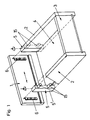
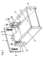
- FIG. 1 and 2 each show a diagram of a drawer with a fastening device according to the invention
- FIG. 3 shows a diagram of a drawer with a front plate fastening device according to the invention and releasable holding devices for the pull-out rail
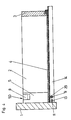
- FIG. 4 shows a side view of a drawer with a detachable Holding device for a pull-out rail
- FIGS. 5 and 6 each show a vertical section perpendicular to the drawer front panel through two different exemplary embodiments of a front panel fastening according to the invention
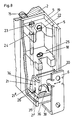
- FIGS. 7 and 8 each show a diagram, partly torn open, of these exemplary embodiments of a front panel fastening according to the invention
- FIG. 9 shows a vertical section parallel to the drawer front panel through a releasable holding device for the pull-out rail.
- the drawer consists in a conventional manner of the two drawer side walls 2, the drawer rear wall 3, the drawer bottom 4 and the front panel 1.
- the drawer side walls 2 are made of wood, a chipboard or the like.
- the drawer can, as can be seen from FIG. 2, also be provided with a front plate 7 which connects the two side walls 2 to one another via the fastening devices 5 for the front panel 1.
- the fastening devices 5 are fastened to the end faces of the drawer side walls 2 by means of dowels 15.
- a dowel strip 16 could also be provided, as is shown in FIG. 2 as a fastening means for fastening device 5 and front plate 7.
- FIGS. 5 and 7 The simpler form of the front panel attachment 5, which only allows the front panel 1 to be adjusted to the side, is shown in FIGS. 5 and 7.
- Each fastening device 5 has a housing 5 'which is directly anchored to the drawer side wall 2 and practically extends the drawer side wall 2 to the front panel 1, that is to say preferably has the same height and width as the drawer side wall 2.
- the supporting part 21 is mounted within the housing 5 '.
- the support part 21 is in two parts and has a support part body 21 ' and an insert part 20 into which the holding part 6 fastened to the front panel 1 by means of screws or the like can be directly hung.
- the support part body 21 'of the support part 21, seen from the front is U-shaped with side flanges 21 "and the snap-in part 20 is U-shaped in plan view with side flanges 20'.
- the snap-in part 20 has side flanges vertical slots 34 protrude into the guide pins 35, which are attached to the side flanges 21 "of the support body 21 '.
- the snap-in part 20 comprises with its flanges 20 'the support part body 21' of the support part 21 and its flanges 21 "and is held in its upper position by a spring 26, whereby it can be pressed down over the length of the slots 34.
- the supporting part 21 rests on a cam 37 in the housing 5 'of the front panel fastening 5.
- the screw 18 protrudes through a nut thread 38 in the lower plate of the support part 21.
- the screw 18 Since the screw 18 is held axially immovably in the housing 5 'of the fastening device 5, when the screw 18 is rotated the support part 21 is tilted around the cam 37. If the screw 18 is turned to such an extent that the supporting part 21 is tilted backwards, ie away from the front panel 1, the holding part 6 is clamped to the supporting part 21.
- the holding parts 6 also have a lower, horizontally projecting stop part 39 which projects between the two side webs 21 "of the supporting part body 21 'and which, when it bears against one of these side webs 21", forms a limit stop for the lateral adjustment possibility of the front panel 1.
- a vertically adjustable cage 25 is arranged in the housing 5 '.
- the cage 25 there are again the support part 21 with the support part body 21 'and the snap-in part 20.
- the assembly of the front panel 1 is carried out in the same way as in the previous exemplary embodiment by hanging the front panel 1 with the holding parts 6 into the snap-in parts 20 and by tensioning the support part 21 by means of the screw 18.
- the cage 25 can be moved up or down by the screw 23, which is mounted in a yoke 19, which is fastened in the housing 5 'by means of a screw 22 and which projects into a nut thread. That is, an adjustment of the front panel 1 in height is possible.
- the screw 23 has a projecting edge 24 which, however, can also be formed by a circlip or the like and which secures the screw 23 in the housing 5 '.
- the detachable holding device for the pull-out rail 14 of the drawer can be provided directly behind the fastening device 5, preferably in an associated housing part 5 ′′.
- the drawer 14 is provided at the rear with a hook 40 with which it can be anchored in the drawer rear wall 3.
- the pull-out rail 14 has a slot 11 which is open to the front and through which a locking pin 13 projecting laterally into the pull-out rail 14 from the drawer or the holding device 50 projects.
- the locking pin 9 is supported on a support pin 27 and is a coil spring 28 to the outside, i. H. pressed into the vertical web 14 'of the pull-out rail 14.
- the locking pin 9 has a stop 33, which is formed for example by a laterally projecting cylindrical edge. At this stop 33 there is an unlocking rod 30, which is arranged vertically in the housing 5 ′′, with a wedge surface 12. The unlocking rod 30 is mounted at its upper end in a push-button-like part 8 and is held in its upper position by a coil spring 32. In this upper position of the unlocking rod 30, the pull-out rail 14 is locked.
- the wedge surface 12 of the unlocking days 30 presses the locking pin 9 laterally outwards via the stop 33, i. H. to the body side wall 49 and thus out of the pull-out rail 14.
- the pull-out rail can now be freely pulled out of its anchoring with the drawer.
- the cabinet-side mounting rail is also shown and provided with the reference number 10.
Landscapes
- Drawers Of Furniture (AREA)
- Connection Of Plates (AREA)
Abstract
Eine Befestigungsvorrichtung (5) für die Frontblende (1) einer Schublade. An der Frontblende (1) sind hakenartige Halteteile (6) befestigbar, die bei der Montage der Frontblende (1) in den Schubladenseitenwänden (2) zugehörige Tragteile (21) einhängbar und mit diesen verspannbar sind. An jeder Seite der Schublade ist ein Gehäuse (5') vorgesehen, das mit Dübel (15) od. dgl. an einer vorzugsweise aus Holzmaterial, beispielsweise einer Spanplatte, gefertigten Seitenwand (2) der Schublade befestigbar ist und in dem ein Tragteil (21) lagert. Weiters ist eine lösbare Haltevorrichtung (50) für eine an der Schublade befestigte Ausziehschiene (14) einer Ausziehführungsgarnitur vorgesehen, wobei die Ausziehschiene (14) hinten einen Haken (40) aufweist, mit dem sie in die Schublade einhängbar ist und vorne einen offenen waagrechten Schlitz (11), in den ein seitlich vorspringender Haltezapfen (13) der Haltevorrichtung (50) ragt. Ein senkrecht zur Ausziehschiene (14) verschiebbarer Arretierzapfen (9), der vorzugsweise von einer Druckfeder (28) beaufschlagt wird, ist mittels einer vertikal bewegbaren Entriegelungsstange (30) aus der Ausziehschiene heraus bewegbar.A fastening device (5) for the front panel (1) of a drawer. Hook-like holding parts (6) can be fastened to the front panel (1) and, when the front panel (1) is installed, associated supporting parts (21) can be hung in the drawer side walls (2) and can be braced with them. A housing (5 ') is provided on each side of the drawer, which can be fastened with dowels (15) or the like to a side wall (2) of the drawer, which is preferably made of wood material, for example a particle board, and in which a supporting part (21 ) stores. Furthermore, a detachable holding device (50) is provided for a pull-out rail (14) of a pull-out guide set fastened to the drawer, the pull-out rail (14) having a hook (40) at the back with which it can be hung in the drawer and an open horizontal slot at the front (11) into which a laterally projecting holding pin (13) of the holding device (50) projects. A locking pin (9) which can be displaced perpendicularly to the pull-out rail (14) and which is preferably acted upon by a compression spring (28) can be moved out of the pull-out rail by means of a vertically movable unlocking rod (30).
Description
Die Erfindung bezieht sich auf eine Befestigungsvorrichtung für die Frontblende einer Schublade, wobei an der Frontblende hakenartige Halteteile befestigbar sind, die bei der Montage der Frontblende in den Schubladenseitenwänden zugehörige Tragteile einhängbar und mit diesen verspannbar sind, wobei an jeder Seite der Schublade ein Gehäuse vorgesehen ist, das mit Dübel od. dgl. an einer aus Holzmaterial, beispielsweise einer Spanplatte, gefertigten Seitenwand der Schublade befestigbar ist und in dem ein Tragteil lagert.The invention relates to a fastening device for the front panel of a drawer, hook-like holding parts can be fastened to the front panel, the associated supporting parts can be suspended and braced with the front panel in the drawer side walls, with a housing being provided on each side of the drawer which can be fastened with dowels or the like to a side wall of the drawer made of wood material, for example a particle board, and in which a supporting part is stored.
Weiters bezieht sich die Erfindung auf eine lösbare Haltevorrichtung für eine an der Schublade befestigte Ausziehschiene einer Ausziehführungsgarnitur, wobei die Ausziehschiene hinten einen Haken aufweist, mit dem sie in die Schublade einhängbar ist und vorne einen offenen waagrechten Schlitz, in den ein seitlich vorspringender Haltezapfen der Schublade oder der Haltevorrichtung ragt.The invention further relates to a releasable holding device for a pull-out rail of a pull-out guide set fastened to the drawer, the pull-out rail having a hook at the back with which it can be hung in the drawer and an open horizontal slot at the front into which a laterally projecting holding pin of the drawer or the holding device protrudes.
Es sind verschiedene Befestigungsvorrichtungen für die Frontblende einer Schublade bekannt, die sich prinzipiell unterscheiden, je nachdem ob die Schubladenseitenwände aus Kunststoffmaterial oder aus Metall gefertigt sind. Bei Schubladenzargen aus Metall ist die Frontblende mittels eines Halteteiles meist direkt in die Schubladenzargen eingehängt bzw. mit diesen verbunden, d. h., der eigentliche Tragteil der Befestigungsvorrichtung für die Frontblende ist Teil der Schubladenzarge. Sind die Schubladenseitenwände jedoch aus Kunststoff gefertigt, dann sind die Ausziehschienen der Ausziehführungsgarnitur der Schublade an ihren vorderen Enden mit winkelförmigen Tragteilen versehen, in die die Halteteile der Befestigungsvorrichtung für die Frontblende einhängbar sind.Various fastening devices for the front panel of a drawer are known, which differ in principle depending on whether the drawer side walls are made of plastic material or metal. In the case of metal drawer frames, the front panel is usually attached or connected directly to the drawer frames by means of a holding part, ie. that is, the actual supporting part of the fastening device for the front panel is part of the drawer frame. However, if the drawer side walls are made of plastic, the pull-out rails of the pull-out guide set of the drawer are provided at their front ends with angular support parts into which the holding parts of the fastening device for the front panel can be hung.
Frontblenden von Holzschubladen werden nach dem bekannten Stand der Technik mit den Seitenwänden der Schublade verdübelt, d. h., daß eine nachträgliche Justierung der Frontblende nicht möglich ist.Front panels of wooden drawers are pegged to the side walls of the drawer according to the known state of the art, i. that is, a subsequent adjustment of the front panel is not possible.
Aufgabe der Erfindung ist es, eine Befestigungsvorrichtung der eingangs erwähnten Art zu schaffen, die insbesondere für die Verankerung einer Frontblende und nachträgliche Positionierung einer Frontblende an einer Schublade mit Seitenwänden aus Holz geeignet ist.The object of the invention is to provide a fastening device of the type mentioned, in particular for the anchoring of a front panel and subsequent positioning of a front panel on a drawer with side walls made of wood is suitable.
Dies wird erfindungsgemäß dadurch erreicht, daß der Tragteil, der von vorne gesehen U-förmig mit seitlichen Flanschen ausgeführt ist, einen in Draufsicht U-förmigen Einrastteil aufnimmt, der in der Höhe verschiebbar ist und von einer Feder beaufschlagt wird, und daß der Tragteil mittels einer im Gehäuse senkrecht angeordneten Schraube, die im Gehäuse drehbar aber axial unverschiebbar gehalten ist, um eine horizontale Achse kippbar ist.This is achieved according to the invention in that the support part, which is U-shaped with side flanges when viewed from the front, accommodates a U-shaped snap-in part in plan view, which is displaceable in height and is acted upon by a spring, and that the support part is by means of a vertically arranged screw in the housing, which is rotatably but axially immovable in the housing and can be tilted about a horizontal axis.
Eine weitere Aufgabe der Erfindung ist es eine lösbare Haltevorrichtung für eine an der Schublade befestigte Ausziehschiene zu schaffen, die zusammen mit der Befestigungsvorrichtung für die Frontblende an der Schubladenseitenwand montiert werden kann und die ebenso wie die Spannmittel der Befestigungsvorrichtung für die Frontblende von oben betätigbar ist.Another object of the invention is to provide a releasable holding device for a pull-out rail fastened to the drawer, which can be mounted together with the fastening device for the front panel on the drawer side wall and which, like the clamping means of the fastening device for the front panel, can be actuated from above.
Dies wird durch einen senkrecht zur Ausziehschiene verschiebbaren Arretierzapfen, der vorzugsweise von einer Druckfeder beaufschlagt wird und in eine Öffnung in der Ausziehschiene ragt und mittels einer vertikal bewegbaren Entriegelungsstange, die von einer Druckfeder in einer oberen Endstellung gehalten wird aus der Ausziehschiene heraus bewegbar ist, wobei die Entriegelungsstange mit einer Keilfläche oder Kante an einem Anschlag des Arretierzapfens anliegt, erreicht.This is made possible by a locking pin that can be moved perpendicular to the pull-out rail, which is preferably acted upon by a compression spring and protrudes into an opening in the pull-out rail, and by means of a vertically movable unlocking rod which is held in an upper end position by a pressure spring, whereby the unlocking rod rests with a wedge surface or edge against a stop of the locking pin.
Nachfolgend werden Ausführungsbeispiele der Erfindung anhand der Figuren der beiliegenden Zeichnungen beschrieben.Exemplary embodiments of the invention are described below with reference to the figures of the accompanying drawings.
Die Fig. 1 und die Fig. 2 zeigen je ein Schaubild einer Schublade mit einer erfindungsgemäßen Befestigungsvorrichtung, die Fig. 3 zeigt ein Schaubild einer Schublade mit einer erfindungsgemäßen Frontplattenbefestigungsvorrichtung und lösbaren Haltevorrichtungen für die Ausziehschiene, die Fig. 4 zeigt eine Seitenansicht einer Schublade mit einer lösbaren Haltevorrichtung für eine Ausziehschiene, die Fig. 5 und 6 zeigen je einen Vertikalschnitt senkrecht zur Schubladenfrontblende durch zwei verschiedene Ausführungsbeispiele einer erfindungsgemäßen Frontblendenbefestigung, die Fig. 7 und 8 zeigen je ein Schaubild, zum Teil aufgerissen, dieser Ausführungsbeispiele einer erfindungsgemäßen Frontblendenbefestigung und die Fig. 9 zeigt einen Vertikalschnitt parallel zur Schubladenfrontblende durch eine lösbare Haltevorrichtung für die Ausziehschiene.1 and 2 each show a diagram of a drawer with a fastening device according to the invention, FIG. 3 shows a diagram of a drawer with a front plate fastening device according to the invention and releasable holding devices for the pull-out rail, FIG. 4 shows a side view of a drawer with a detachable Holding device for a pull-out rail, FIGS. 5 and 6 each show a vertical section perpendicular to the drawer front panel through two different exemplary embodiments of a front panel fastening according to the invention, FIGS. 7 and 8 each show a diagram, partly torn open, of these exemplary embodiments of a front panel fastening according to the invention and FIG. 9 shows a vertical section parallel to the drawer front panel through a releasable holding device for the pull-out rail.
Die Schublade besteht in herkömmlicher Weise aus den beiden Schubladenseitenwänden 2, der Schubladenrückwand 3, dem Schubladenboden 4 und der Frontblende 1. Die Schubladenseitenwände 2 sind aus Holz, einer Spanplatte od. dgl. gefertigt.The drawer consists in a conventional manner of the two
Zusätzlich zur Frontblende 1 kann die Schublade, wie aus der Fig. 2 ersichtlich, noch mit einer Frontplatte 7 versehen sein, die die beiden Seitenwände 2 miteinander über die Befestigungsvorrichtungen 5 für die Frontblende 1 verbindet.In addition to the front panel 1, the drawer can, as can be seen from FIG. 2, also be provided with a front plate 7 which connects the two
Die Befestigungsvorrichtungen 5 sind an den Stirnseiten der Schubladenseitenwände 2 mittels Dübel 15 befestigt. Anstelle der Dübel 15 könnte auch eine Dübelleiste 16 vorgesehen sein, wie sie in der Fig. 2 als Befestigungsmittel für Befestigungsvorrichtung 5 und Frontplatte 7 gezeigt ist.The
Die einfachere Form der Frontblendenbefestigung 5, die nur eine Verstellung der Frontblende 1 zur Seite ermöglicht, ist in den Fig. 5 und 7 gezeigt.The simpler form of the
Jede Befestigungsvorrichtung 5 weist ein Gehäuse 5' auf, das unmittelbar mit der Schubladenseitenwand 2 verdübelt ist und die Schubladenseitenwand 2 praktisch bis zur Frontblende 1 verlängert, also vorzugsweise gleiche Höhe und Breite wie die Schubladenseitenwand 2 aufweist.Each
Innerhalb des Gehäuses 5' ist der Tragteil 21 gelagert. Der Tragteil 21 ist zweiteilig und weist einen Tragteilkörper 21' und einen Einsatzteil 20 auf, in den der an der Frontblende 1 mittels Schrauben od. dgl. befestigte Halteteil 6 unmittelbar einhängbar ist.The supporting
Wie aus den Fig. 5 und 7 ersichtlich, ist der Tragteilkörper 21' des Tragteiles 21 von vorne gesehen U-förmig mit seitlichen Flanschen 21" und der Einrastteil 20 ist in Draufsicht U-förmig mit seitlichen Flanschen 20'. Der Einrastteil 20 weist seitliche vertikale Schlitze 34 auf, in die Führungszapfen 35, die an den Seitenflanschen 21" des Tragteilkörpers 21' befestigt sind, ragen. Der Einrastteil 20 umfaßt mit seinen Flanschen 20' den Tragteilkörper 21' des Tragteiles 21 und dessen Flansche 21" und wird von einer Feder 26 in seiner oberen Position gehalten, wobei er über die Länge der Schlitze 34 nach unten gedrückt werden kann. Dies ermöglicht das Einhängen der Frontblende 1 bei in den Korpus eingeschobener Schublade, da die Frontblende 1 unter die bereits montierte Frontblende 1 einer darüberliegenden Schublade oder unter einen hervorspringenden Rand des Oberbodens in exakt in der Höhe in die Frontblendenbefestigung 5 eingeschoben werden kann, in der sie anschließend gehalten werden soll. Die Länge der Schlitze 34 muß also mindestens so lang sein wie die Höhe der Haken 36 der Halteteile 6.5 and 7, the support part body 21 'of the
Befindet sich die Frontblende 1 mit den Halteteilen 6 in der eingehängten Position wird die Schraube 18 verdreht.If the front panel 1 with the
Wie insbesondere aus der Fig. 5 ersichtlich, liegt der Tragteil 21 auf einer Nocke 37 im Gehäuse 5' der Frontplattenbefestigung 5 auf. Die Schraube 18 ragt durch ein Muttergewinde 38 in der unteren Platte des Tragteiles 21.As can be seen in particular from FIG. 5, the supporting
Da die Schraube 18 im Gehäuse 5' der Befestigungsvorrichtung 5 axial unverschiebbar gehalten ist, wird beim Verdrehen der Schraube 18 der Tragteil 21 um die Nocke 37 gekippt. Erfolgt das Verdrehen der Schraube 18 dermaßen, daß der Tragteil 21 nach hinten, d. h. weg von der Frontblende 1 gekippt wird, wird der Halteteil 6 mit dem Tragteil 21 verspannt.Since the
Die Halteteile 6 haben noch einen unteren waagrecht vorspringenden Anschlagteil 39, der zwischen die beiden Seitenstege 21" des Tragteilkörpers 21' ragt und der, wenn er an einem dieser Seitenstege 21" anliegt, einen Begrenzungsanschlag für die seitliche Verstellmöglichkeit der Frontblende 1 bildet.The
Im Ausführungsbeispiel nach den Fig. 6 und 9 ist im Gehäuse 5' ein vertikal verstellbarer Käfig 25 angeordnet. Im Käfig 25 befinden sich wieder der Tragteil 21 mit dem Tragteilkörper 21' und dem Einrastteil 20. Die Montage der Frontblende 1 erfolgt gleich wie beim vorhergehenden Ausführungsbeispiel durch Einhängen der Frontblende 1 mit den Halteteilen 6 in die Einrastteile 20 und durch Verspannen des Tragteiles 21 mittels der Schraube 18.In the exemplary embodiment according to FIGS. 6 and 9, a vertically
Durch die Schraube 23, die in einem Joch 19, welches mittels einer Schraube 22 im Gehäuse 5' befestigt ist, gelagert ist und die in ein Muttergewinde im Käfig 25 ragt, kann der Käfig 25 nach oben oder nach unten bewegt werden, d. h., es ist eine Verstellung der Frontblende 1 in der Höhe möglich. Die Schraube 23 weist einen vorspringenden Rand 24 auf, der jedoch auch von einem Seegerring od. dgl. gebildet werden kann und der die Schraube 23 im Gehäuse 5' sichert.The
Wie aus der Fig. 3 ersichtlich, kann unmittelbar hinter der Befestigungsvorrichtung 5 vorzugsweise in einem dazugehörigen Gehäuseteil 5" die lösbare Haltevorrichtung für die Ausziehschiene 14 der Schublade vorgesehen sein.As can be seen from FIG. 3, the detachable holding device for the pull-out
Die Schublade 14 ist hinten mit einem Haken 40 versehen, mit dem sie in der Schubladenrückwand 3 verankerbar ist.The
Vorne weist die Ausziehschiene 14 einen nach vorne offenen Schlitz 11 auf, durch den ein von der Schublade bzw. der Haltevorrichtung 50 seitlich in die Ausziehschiene 14 vorspringender Arretierzapfen 13 ragt.At the front, the pull-out
Um die Ausziehschiene 14 von der Schublade zu entfernen muß sie nach hinten von der Schublade aus ihrer Verankerung (Bolzen 13, Loch für Haken 40) herausgezogen werden. Dies verhindert ein Arretierzapfen 9, der im Normalzustand durch ein korrespondierendes Loch 29 in der Ausziehschiene 14 ragt und der in der Haltevorrichtung 50 horizontal in einer Ebene parallel zur Frontblende 1 verschiebbar ist.In order to remove the pull-out
Der Arretierzapfen 9 lagert dabei auf einem Tragzapfen 27 und wird von einer Schraubenfeder 28 nach außen, d. h. in den Vertikalsteg 14' der Ausziehschiene 14 gedrückt.The
Der Arretierzapfen 9 weist einen Anschlag 33 auf, der beispielsweise von einem seitlich vorstehenden zylindrischen Rand gebildet wird. An diesem Anschlag 33 liegt eine Entriegelungsstange 30, die im Gehäuse 5" vertikal angeordnet ist, mit einer Keilfläche 12 an. Die Entriegelungsstange 30 ist an ihrem oberen Ende in einem drucktastenartigen Teil 8 gelagert und wird von einer Schraubenfeder 32 in ihrer oberen Stellung gehalten. In dieser oberen Stellung der Entriegelungsstange 30 ist die Ausziehschiene 14 arretiert.The
Wird nun durch Druck auf den tastenförmigen Teil 8 die Entriegelungsstange 30 nach unten bewegt, drückt die Keilfläche 12 der Entriegelunsstage 30 den Arretierzapfen 9 über den Anschlag 33 seitlich nach außen, d. h. zur Korpusseitenwand 49 und somit aus der Ausziehschiene 14 heraus. Die Ausziehschiene kann nun frei nach hinten aus ihrer Verankerung mit der Schublade herausgezogen werden.If the
In den Fig. 3 und 9 ist noch die korpusseitige Tragschiene eingezeichnet und mit dem Bezugszeichen 10 versehen.3 and 9, the cabinet-side mounting rail is also shown and provided with the
Claims (10)
Priority Applications (1)
| Application Number | Priority Date | Filing Date | Title |
|---|---|---|---|
| EP93114544A EP0581325B1 (en) | 1990-01-22 | 1990-12-12 | Releasable retaining device for a drawer rail |
Applications Claiming Priority (2)
| Application Number | Priority Date | Filing Date | Title |
|---|---|---|---|
| AT0012490A AT398265B (en) | 1990-01-22 | 1990-01-22 | FASTENING DEVICE FOR THE FRONT PANEL OF A DRAWER |
| AT124/90 | 1990-01-22 |
Related Child Applications (1)
| Application Number | Title | Priority Date | Filing Date |
|---|---|---|---|
| EP93114544.5 Division-Into | 1993-09-10 |
Publications (3)
| Publication Number | Publication Date |
|---|---|
| EP0439748A2 true EP0439748A2 (en) | 1991-08-07 |
| EP0439748A3 EP0439748A3 (en) | 1991-11-27 |
| EP0439748B1 EP0439748B1 (en) | 1995-03-08 |
Family
ID=3482146
Family Applications (2)
| Application Number | Title | Priority Date | Filing Date |
|---|---|---|---|
| EP90123990A Expired - Lifetime EP0439748B1 (en) | 1990-01-22 | 1990-12-12 | Fixing device for drawer front |
| EP93114544A Expired - Lifetime EP0581325B1 (en) | 1990-01-22 | 1990-12-12 | Releasable retaining device for a drawer rail |
Family Applications After (1)
| Application Number | Title | Priority Date | Filing Date |
|---|---|---|---|
| EP93114544A Expired - Lifetime EP0581325B1 (en) | 1990-01-22 | 1990-12-12 | Releasable retaining device for a drawer rail |
Country Status (7)
| Country | Link |
|---|---|
| US (2) | US5222791A (en) |
| EP (2) | EP0439748B1 (en) |
| JP (1) | JPH0813285B2 (en) |
| AT (3) | AT398265B (en) |
| CA (1) | CA2034050A1 (en) |
| DE (2) | DE59008650D1 (en) |
| ES (2) | ES2068978T3 (en) |
Cited By (11)
| Publication number | Priority date | Publication date | Assignee | Title |
|---|---|---|---|---|
| AT398516B (en) * | 1992-02-05 | 1994-12-27 | Fulterer Gmbh | DRAWER EXTENSION |
| AT400796B (en) * | 1993-02-10 | 1996-03-25 | Blum Gmbh Julius | DRAWER KIT |
| AT402598B (en) * | 1995-03-23 | 1997-06-25 | Fulterer Gmbh | Drawer runner |
| EP0702915A3 (en) * | 1994-09-21 | 1998-07-22 | Paul Hettich Gmbh & Co. | Fitting for adjustable setting of a front panel |
| EP2025261A1 (en) * | 2007-08-16 | 2009-02-18 | Anton Schneider Gmbh & Co. | Device for securing front bezels for drawers |
| ITMC20110058A1 (en) * | 2011-10-26 | 2013-04-27 | Essetre S R L | DRAWER PERFECTED WITH FRONT DOOR EQUIPPED WITH ADJUSTMENT AND LOCKING EQUIPMENT FOR SUCH FRONT DOOR. |
| AT512753A1 (en) * | 2012-04-05 | 2013-10-15 | Baliko Karl Ing | Arrangement for connecting a drawer side wall with another drawer wall |
| DE202012010755U1 (en) * | 2012-11-09 | 2014-02-14 | Grass Gmbh | Device for connecting a front to a side part of a movable furniture part |
| WO2016015865A1 (en) * | 2014-07-30 | 2016-02-04 | Erwin Krüger | Fastening fitting for a drawer front on an open side of a drawer |
| DE102015109459A1 (en) * | 2015-05-05 | 2016-11-10 | Form Orange Produktentwicklung | Drawer with a base plate, two side walls, a rear wall and a bottom plate |
| WO2024016031A1 (en) | 2022-07-21 | 2024-01-25 | Julius Blum Gmbh | Method for connecting a front panel to a drawer lateral wall |
Families Citing this family (38)
| Publication number | Priority date | Publication date | Assignee | Title |
|---|---|---|---|---|
| IT229906Y1 (en) * | 1993-05-13 | 1999-02-05 | Ferrari Franco | DEVICE FOR FIXING AND ADJUSTING THE FRONT OF A DRAWER WITH RESPECT TO THE SIDE |
| US5476317A (en) * | 1994-04-29 | 1995-12-19 | Grubb; Jeffrey A. | Convertible desk drawer |
| AT404664B (en) * | 1995-03-20 | 1999-01-25 | Blum Gmbh Julius | DEVICE FOR FASTENING THE FRONT PANEL OF A DRAWER ON DRAWER FRAMES |
| GB2314006A (en) * | 1996-06-12 | 1997-12-17 | Dennis Bagley | Repair kit for furniture drawers |
| US5823700A (en) * | 1996-09-18 | 1998-10-20 | Bush Industries, Inc. | Drawer front fastener |
| EP0875176B1 (en) * | 1997-04-29 | 2003-05-07 | Alfit Aktiengesellschaft | Drawer |
| DE19722392A1 (en) * | 1997-05-28 | 1998-12-03 | Breeze Tv Gmbh | Hanging frame for sales display of compact disks |
| GB2354933A (en) * | 1999-10-07 | 2001-04-11 | Accuride Int Ltd | Drawer with drawer slide quick release mechanism |
| AT409067B (en) * | 2000-03-02 | 2002-05-27 | Blum Gmbh Julius | EXTENDING GUIDE FOR DRAWERS |
| DE20120242U1 (en) * | 2001-12-14 | 2002-02-28 | Paul Hettich Gmbh & Co., 32278 Kirchlengern | Bottom drawer for a piece of furniture |
| MY134353A (en) * | 2002-05-20 | 2007-12-31 | Harn Marketing Sdn Bhd | An improved front panel mounting device for a drawer |
| US6757937B2 (en) * | 2002-10-09 | 2004-07-06 | Arturo Salice S.P.A. | Apparatus to mount a support rail of a drawer guide to a wall of a piece of furniture |
| US7207637B2 (en) * | 2004-04-07 | 2007-04-24 | King Slide Works Co., Ltd. | Coupling apparatus for a side panel and a face panel of drawers |
| US7140609B2 (en) * | 2004-08-16 | 2006-11-28 | Hewlett-Packard Development Company, L.P. | Locking/unlocking mechanism |
| AT413583B (en) * | 2004-10-08 | 2006-04-15 | Blum Gmbh Julius | STABILIZATION DEVICE FOR FURNITURE PARTS |
| USD577936S1 (en) | 2005-09-13 | 2008-10-07 | Julius Blum Gmbh | Side wall of a drawer |
| USD563125S1 (en) * | 2005-09-13 | 2008-03-04 | Julius Blum Gmbh | Side wall of a drawer |
| DE202007015212U1 (en) * | 2007-11-02 | 2008-01-24 | Anton Schneider Gmbh & Co Kg | Fastening device for furniture parts |
| USD615327S1 (en) * | 2008-02-22 | 2010-05-11 | Harn Marketing Sdn. Bhd. | Sink drawer |
| DE202008008540U1 (en) * | 2008-06-30 | 2009-11-19 | Paul Hettich Gmbh & Co. Kg | wall element |
| DE202010007428U1 (en) * | 2010-05-31 | 2011-09-05 | Grass Gmbh | Connecting device and drawer with a connecting device |
| DE202010007430U1 (en) * | 2010-05-31 | 2011-09-05 | Grass Gmbh | Device with an attachment device and drawer |
| AT13204U1 (en) * | 2010-10-19 | 2013-08-15 | Karl Ing Baliko | FRONT PANEL MOUNTING |
| AT511418B1 (en) * | 2011-05-05 | 2014-11-15 | Blum Gmbh Julius | EXTRACTION GUIDE FOR A DRAWER |
| AT511906B1 (en) * | 2011-08-30 | 2016-05-15 | Blum Gmbh Julius | DRAWER |
| CN103455110A (en) * | 2012-06-01 | 2013-12-18 | 鸿富锦精密工业(深圳)有限公司 | Server tray |
| BR112017021968B8 (en) * | 2015-04-30 | 2021-04-20 | Salice Arturo Spa | mountable drawer for furniture and method for assembling the drawer |
| US9730517B2 (en) | 2015-05-27 | 2017-08-15 | Steelcase Inc. | Storage assembly with pull-out arrangement |
| CN107809927A (en) * | 2015-06-15 | 2018-03-16 | 形橙产品开发公司 | Drawer with bottom plate, two side walls, rear wall and baffle plate |
| DE102015110561A1 (en) * | 2015-07-01 | 2017-01-05 | Form Orange Produktentwicklung | Drawer with a bottom plate, a cover, a rear wall and two side walls, which are firmly connected |
| CN108236237B (en) * | 2016-12-27 | 2020-10-27 | 川湖科技股份有限公司 | Slide rail mechanism and adjustment assembly for slide rail |
| KR101877254B1 (en) * | 2017-08-30 | 2018-07-11 | (주)퍼맥스 | Drawer |
| CN108391991B (en) * | 2018-03-27 | 2024-06-11 | 广东星鹏实业有限公司 | Panel fastener of activity locking |
| TWI712381B (en) * | 2020-02-25 | 2020-12-11 | 川湖科技股份有限公司 | Mounting device and mounting method for furniture assembly |
| CN111369891B (en) * | 2020-04-29 | 2022-03-11 | 台州万博建筑工程有限公司 | Municipal administration slogan tablet fixing device |
| CN111879047A (en) * | 2020-07-09 | 2020-11-03 | 海信容声(广东)冰箱有限公司 | A kind of refrigerator |
| US12018881B2 (en) * | 2020-11-23 | 2024-06-25 | Whirlpool Corporation | Adjustment assembly for appliance door |
| DE102022106236B4 (en) | 2022-03-17 | 2023-10-12 | Bastian Demmer & Jens-Oliver Bahr GbR | Drawer |
Family Cites Families (15)
| Publication number | Priority date | Publication date | Assignee | Title |
|---|---|---|---|---|
| US3207565A (en) * | 1964-06-29 | 1965-09-21 | Scharge Jack | Concealed drawers for furniture and the like |
| AT282106B (en) * | 1967-11-01 | 1970-06-10 | Osta Werke Gmbh | Furniture part that can be pulled out like a drawer |
| US3752553A (en) * | 1971-07-29 | 1973-08-14 | Amerock Corp | Drawer with snap-on front panel |
| AT322140B (en) * | 1973-10-30 | 1975-05-12 | Kemetmueller Herbert | DEVICE FOR ALIGNING AND FASTENING A DRAWER FRONT PIECE TO THE FRONT FRAME PART OF A DRAWER |
| DE2610200C3 (en) * | 1976-03-11 | 1980-01-31 | Richard Heinze Gmbh & Co Kg, 4900 Herford | Fitting for the detachable connection of two components, in particular panel-shaped components for furniture |
| DE2759349C2 (en) * | 1977-02-25 | 1983-07-14 | Hans-Werner 4830 Gütersloh Düpree | Plastic drawer |
| DE2745896A1 (en) * | 1977-10-12 | 1979-04-19 | Heinze Fa R | Adjustable furniture fitting and assembly - is especially used for screening of sliding drawers and includes turnable eccentric bolt |
| AT365431B (en) * | 1980-06-06 | 1982-01-11 | Blum Gmbh Julius | EXTENSION GUIDE SET, ESPECIALLY FOR SPECIAL BOARDS |
| DE3114809A1 (en) * | 1980-06-07 | 1982-06-03 | Schock Metallwerk Gmbh, 7067 Urbach | ELEVATOR GUIDE FOR EXTENSIBLE CARRIERS LIKE DRAWERS OR THE LIKE. |
| IT8411803U1 (en) * | 1984-08-14 | 1986-02-14 | Dezi Legnami S P A | A furniture drawer structure made of waterproof panels held together by screws |
| FR2604876B1 (en) * | 1986-10-13 | 1990-06-01 | Folliet Henri | ORDERLY STORAGE COMPARTMENT |
| AT391407B (en) * | 1986-11-12 | 1990-10-10 | Blum Gmbh Julius | FASTENING DEVICE FOR ADJUSTABLE FRONT PANELS OF DRAWERS |
| AT391987B (en) * | 1987-02-04 | 1990-12-27 | Blum Gmbh Julius | FASTENING DEVICE FOR ADJUSTABLE FRONT PANELS OF DRAWERS |
| AT399260B (en) * | 1987-05-22 | 1995-04-25 | Blum Gmbh Julius | DRAWER |
| DE8802690U1 (en) * | 1988-03-01 | 1988-04-07 | Ninkaplast Gmbh, 4902 Bad Salzuflen | Locking part, especially for elevator rails |
-
1990
- 1990-01-22 AT AT0012490A patent/AT398265B/en not_active IP Right Cessation
- 1990-12-12 EP EP90123990A patent/EP0439748B1/en not_active Expired - Lifetime
- 1990-12-12 AT AT93114544T patent/ATE149078T1/en not_active IP Right Cessation
- 1990-12-12 AT AT90123990T patent/ATE119362T1/en not_active IP Right Cessation
- 1990-12-12 DE DE59008650T patent/DE59008650D1/en not_active Expired - Fee Related
- 1990-12-12 DE DE59010656T patent/DE59010656D1/en not_active Expired - Fee Related
- 1990-12-12 EP EP93114544A patent/EP0581325B1/en not_active Expired - Lifetime
- 1990-12-12 ES ES90123990T patent/ES2068978T3/en not_active Expired - Lifetime
- 1990-12-12 ES ES93114544T patent/ES2098610T3/en not_active Expired - Lifetime
-
1991
- 1991-01-11 CA CA002034050A patent/CA2034050A1/en not_active Abandoned
- 1991-01-18 US US07/644,733 patent/US5222791A/en not_active Expired - Fee Related
- 1991-01-22 JP JP3020381A patent/JPH0813285B2/en not_active Expired - Lifetime
-
1993
- 1993-02-03 US US08/015,363 patent/US5352034A/en not_active Expired - Fee Related
Cited By (23)
| Publication number | Priority date | Publication date | Assignee | Title |
|---|---|---|---|---|
| AT398516B (en) * | 1992-02-05 | 1994-12-27 | Fulterer Gmbh | DRAWER EXTENSION |
| AT400796B (en) * | 1993-02-10 | 1996-03-25 | Blum Gmbh Julius | DRAWER KIT |
| EP0702915A3 (en) * | 1994-09-21 | 1998-07-22 | Paul Hettich Gmbh & Co. | Fitting for adjustable setting of a front panel |
| AT402598B (en) * | 1995-03-23 | 1997-06-25 | Fulterer Gmbh | Drawer runner |
| EP2025261A1 (en) * | 2007-08-16 | 2009-02-18 | Anton Schneider Gmbh & Co. | Device for securing front bezels for drawers |
| US8038234B2 (en) | 2007-08-16 | 2011-10-18 | Anton Schneider Gmbh & Co. Kg | Device for mounting of drawer front panels |
| US9119468B2 (en) | 2011-10-26 | 2015-09-01 | Essetre S.R.L. | Drawer with front door provided with locking-regulating apparatus of said front door |
| ITMC20110058A1 (en) * | 2011-10-26 | 2013-04-27 | Essetre S R L | DRAWER PERFECTED WITH FRONT DOOR EQUIPPED WITH ADJUSTMENT AND LOCKING EQUIPMENT FOR SUCH FRONT DOOR. |
| WO2013060709A1 (en) * | 2011-10-26 | 2013-05-02 | Essetre S.R.L. | An improved drawer with front door provided with locking-regulating apparatus of said front door |
| AT512753B1 (en) * | 2012-04-05 | 2017-03-15 | Van Hoecke Nv | Arrangement for connecting a drawer side wall with another drawer wall |
| AT512753A1 (en) * | 2012-04-05 | 2013-10-15 | Baliko Karl Ing | Arrangement for connecting a drawer side wall with another drawer wall |
| DE202012010755U1 (en) * | 2012-11-09 | 2014-02-14 | Grass Gmbh | Device for connecting a front to a side part of a movable furniture part |
| EP2730195A1 (en) * | 2012-11-09 | 2014-05-14 | Grass GmbH | Device for connecting a front of a movable part of a piece of furniture to its side element |
| DE202015009975U1 (en) | 2014-07-30 | 2022-02-16 | Wolfgang Held | Fastening fitting for a panel on an open front side of a drawer |
| WO2016015865A1 (en) * | 2014-07-30 | 2016-02-04 | Erwin Krüger | Fastening fitting for a drawer front on an open side of a drawer |
| AT17700U1 (en) * | 2014-07-30 | 2022-11-15 | Held Wolfgang | Fastening fitting for a panel on an open front side of a drawer |
| US10568427B2 (en) | 2014-07-30 | 2020-02-25 | Wolfgang Held | Fastening fitting for a drawer front on an open side of a drawer |
| DE102015109459A1 (en) * | 2015-05-05 | 2016-11-10 | Form Orange Produktentwicklung | Drawer with a base plate, two side walls, a rear wall and a bottom plate |
| WO2016202823A1 (en) * | 2015-05-05 | 2016-12-22 | Form Orange Produktentwicklung | Drawer with a base, two lateral walls, a rear wall, and a panel |
| WO2024016031A1 (en) | 2022-07-21 | 2024-01-25 | Julius Blum Gmbh | Method for connecting a front panel to a drawer lateral wall |
| AT526394A1 (en) * | 2022-07-21 | 2024-02-15 | Blum Gmbh Julius | Drawer side wall for one drawer |
| TWI873700B (en) * | 2022-07-21 | 2025-02-21 | 奧地利商朱利葉斯百隆股份有限公司 | Method for mounting a front panel on a drawer side wall |
| US12440027B2 (en) | 2022-07-21 | 2025-10-14 | Julius Blum Gmbh | Method for connecting a front panel to a drawer lateral wall |
Also Published As
| Publication number | Publication date |
|---|---|
| AT398265B (en) | 1994-11-25 |
| DE59008650D1 (en) | 1995-04-13 |
| EP0581325B1 (en) | 1997-02-26 |
| ATE149078T1 (en) | 1997-03-15 |
| ATA12490A (en) | 1994-03-15 |
| EP0581325A3 (en) | 1994-03-09 |
| ES2098610T3 (en) | 1997-05-01 |
| JPH04329905A (en) | 1992-11-18 |
| US5352034A (en) | 1994-10-04 |
| CA2034050A1 (en) | 1991-07-23 |
| EP0439748B1 (en) | 1995-03-08 |
| EP0439748A3 (en) | 1991-11-27 |
| DE59010656D1 (en) | 1997-04-03 |
| EP0581325A2 (en) | 1994-02-02 |
| US5222791A (en) | 1993-06-29 |
| ATE119362T1 (en) | 1995-03-15 |
| JPH0813285B2 (en) | 1996-02-14 |
| ES2068978T3 (en) | 1995-05-01 |
Similar Documents
| Publication | Publication Date | Title |
|---|---|---|
| EP0439748B1 (en) | Fixing device for drawer front | |
| EP0267477B1 (en) | Fastening device for adjustable drawer fronts | |
| DE3713254C2 (en) | ||
| AT402778B (en) | Device for fixing the front panel of a drawer to drawer sides | |
| AT404664B (en) | DEVICE FOR FASTENING THE FRONT PANEL OF A DRAWER ON DRAWER FRAMES | |
| AT404219B (en) | DRAWER | |
| DE3801816C2 (en) | Fastening device for adjustable front panels of drawers | |
| EP0474966B1 (en) | Anchorage fitting for drawer front panels | |
| EP1147725B1 (en) | Sliding guide-rail for drawers | |
| DE3832701C2 (en) | Fastening arrangement for the guide rail of a pull-out guide | |
| EP0289866B1 (en) | Device for the clamping of a front plate to a metallic drawer frame | |
| EP0647108B1 (en) | Drawer construction set | |
| EP0862873B1 (en) | Fitting for attachment and drawer with such a fitting | |
| EP0664984A2 (en) | Sequential drawer slide or the like | |
| AT314U1 (en) | DRAWER KIT | |
| DE3611480C2 (en) | ||
| AT398516B (en) | DRAWER EXTENSION | |
| EP1238605A1 (en) | Suspension fitting for cabinet | |
| DE3135788A1 (en) | Fastening device for adjustable front panels | |
| DE4335393A1 (en) | Adjusting element for inclination adjustment of the front panel of drawers, drawer-type elements and the like | |
| AT402997B (en) | DEVICE FOR FASTENING THE FRONT PANEL OF A DRAWER | |
| DE4109695C1 (en) | ||
| AT401850B (en) | CONNECTOR FOR CONNECTING A FRONT PANEL OF A DRAWER | |
| AT387316B (en) | Drawer that can be assembled from a plurality of parts | |
| AT368688B (en) | FASTENING DEVICE FOR ADJUSTABLE FRONT PANELS OF EXTENDABLE FURNITURE PARTS |
Legal Events
| Date | Code | Title | Description |
|---|---|---|---|
| PUAI | Public reference made under article 153(3) epc to a published international application that has entered the european phase |
Free format text: ORIGINAL CODE: 0009012 |
|
| AK | Designated contracting states |
Kind code of ref document: A2 Designated state(s): AT DE ES FR GB IT SE |
|
| PUAL | Search report despatched |
Free format text: ORIGINAL CODE: 0009013 |
|
| AK | Designated contracting states |
Kind code of ref document: A3 Designated state(s): AT DE ES FR GB IT SE |
|
| 17P | Request for examination filed |
Effective date: 19911023 |
|
| 17Q | First examination report despatched |
Effective date: 19930507 |
|
| GRAA | (expected) grant |
Free format text: ORIGINAL CODE: 0009210 |
|
| AK | Designated contracting states |
Kind code of ref document: B1 Designated state(s): AT DE ES FR GB IT SE |
|
| REF | Corresponds to: |
Ref document number: 119362 Country of ref document: AT Date of ref document: 19950315 Kind code of ref document: T |
|
| XX | Miscellaneous (additional remarks) |
Free format text: TEILANMELDUNG 93114544.5 EINGEREICHT AM 12/12/90. |
|
| GBT | Gb: translation of ep patent filed (gb section 77(6)(a)/1977) |
Effective date: 19950306 |
|
| REF | Corresponds to: |
Ref document number: 59008650 Country of ref document: DE Date of ref document: 19950413 |
|
| ITF | It: translation for a ep patent filed | ||
| REG | Reference to a national code |
Ref country code: ES Ref legal event code: FG2A Ref document number: 2068978 Country of ref document: ES Kind code of ref document: T3 |
|
| ET | Fr: translation filed | ||
| PLBE | No opposition filed within time limit |
Free format text: ORIGINAL CODE: 0009261 |
|
| STAA | Information on the status of an ep patent application or granted ep patent |
Free format text: STATUS: NO OPPOSITION FILED WITHIN TIME LIMIT |
|
| 26N | No opposition filed | ||
| PGFP | Annual fee paid to national office [announced via postgrant information from national office to epo] |
Ref country code: GB Payment date: 19991208 Year of fee payment: 10 |
|
| PGFP | Annual fee paid to national office [announced via postgrant information from national office to epo] |
Ref country code: AT Payment date: 19991214 Year of fee payment: 10 |
|
| PGFP | Annual fee paid to national office [announced via postgrant information from national office to epo] |
Ref country code: SE Payment date: 19991217 Year of fee payment: 10 |
|
| PGFP | Annual fee paid to national office [announced via postgrant information from national office to epo] |
Ref country code: ES Payment date: 19991228 Year of fee payment: 10 |
|
| PGFP | Annual fee paid to national office [announced via postgrant information from national office to epo] |
Ref country code: FR Payment date: 19991230 Year of fee payment: 10 Ref country code: DE Payment date: 19991230 Year of fee payment: 10 |
|
| PG25 | Lapsed in a contracting state [announced via postgrant information from national office to epo] |
Ref country code: GB Free format text: LAPSE BECAUSE OF NON-PAYMENT OF DUE FEES Effective date: 20001212 Ref country code: AT Free format text: LAPSE BECAUSE OF NON-PAYMENT OF DUE FEES Effective date: 20001212 |
|
| PG25 | Lapsed in a contracting state [announced via postgrant information from national office to epo] |
Ref country code: SE Free format text: LAPSE BECAUSE OF NON-PAYMENT OF DUE FEES Effective date: 20001213 |
|
| GBPC | Gb: european patent ceased through non-payment of renewal fee |
Effective date: 20001212 |
|
| EUG | Se: european patent has lapsed |
Ref document number: 90123990.5 |
|
| PG25 | Lapsed in a contracting state [announced via postgrant information from national office to epo] |
Ref country code: FR Free format text: LAPSE BECAUSE OF NON-PAYMENT OF DUE FEES Effective date: 20010831 |
|
| REG | Reference to a national code |
Ref country code: FR Ref legal event code: ST |
|
| PG25 | Lapsed in a contracting state [announced via postgrant information from national office to epo] |
Ref country code: DE Free format text: LAPSE BECAUSE OF NON-PAYMENT OF DUE FEES Effective date: 20011002 |
|
| PG25 | Lapsed in a contracting state [announced via postgrant information from national office to epo] |
Ref country code: ES Free format text: LAPSE BECAUSE OF NON-PAYMENT OF DUE FEES Effective date: 20011213 |
|
| REG | Reference to a national code |
Ref country code: ES Ref legal event code: FD2A Effective date: 20020112 |
|
| PG25 | Lapsed in a contracting state [announced via postgrant information from national office to epo] |
Ref country code: IT Free format text: LAPSE BECAUSE OF NON-PAYMENT OF DUE FEES;WARNING: LAPSES OF ITALIAN PATENTS WITH EFFECTIVE DATE BEFORE 2007 MAY HAVE OCCURRED AT ANY TIME BEFORE 2007. THE CORRECT EFFECTIVE DATE MAY BE DIFFERENT FROM THE ONE RECORDED. Effective date: 20051212 |