EP0439903B1 - Aufzeichnungs- und Wiedergabesystem - Google Patents
Aufzeichnungs- und Wiedergabesystem Download PDFInfo
- Publication number
- EP0439903B1 EP0439903B1 EP90311274A EP90311274A EP0439903B1 EP 0439903 B1 EP0439903 B1 EP 0439903B1 EP 90311274 A EP90311274 A EP 90311274A EP 90311274 A EP90311274 A EP 90311274A EP 0439903 B1 EP0439903 B1 EP 0439903B1
- Authority
- EP
- European Patent Office
- Prior art keywords
- samples
- frequency
- recording
- signals
- output
- Prior art date
- Legal status (The legal status is an assumption and is not a legal conclusion. Google has not performed a legal analysis and makes no representation as to the accuracy of the status listed.)
- Expired - Lifetime
Links
- 238000005070 sampling Methods 0.000 claims description 10
- 238000001514 detection method Methods 0.000 claims description 8
- 230000004044 response Effects 0.000 description 4
- 230000002045 lasting effect Effects 0.000 description 3
- 238000012360 testing method Methods 0.000 description 3
- 238000010586 diagram Methods 0.000 description 2
- 230000000694 effects Effects 0.000 description 2
- 238000013459 approach Methods 0.000 description 1
- 230000008901 benefit Effects 0.000 description 1
- 238000012937 correction Methods 0.000 description 1
- WSFSSNUMVMOOMR-UHFFFAOYSA-N formaldehyde Substances O=C WSFSSNUMVMOOMR-UHFFFAOYSA-N 0.000 description 1
- 238000000034 method Methods 0.000 description 1
- 238000012986 modification Methods 0.000 description 1
- 230000004048 modification Effects 0.000 description 1
- 238000012545 processing Methods 0.000 description 1
- 230000005236 sound signal Effects 0.000 description 1
- 230000007723 transport mechanism Effects 0.000 description 1
Images



Classifications
-
- G—PHYSICS
- G11—INFORMATION STORAGE
- G11B—INFORMATION STORAGE BASED ON RELATIVE MOVEMENT BETWEEN RECORD CARRIER AND TRANSDUCER
- G11B20/00—Signal processing not specific to the method of recording or reproducing; Circuits therefor
-
- G—PHYSICS
- G11—INFORMATION STORAGE
- G11B—INFORMATION STORAGE BASED ON RELATIVE MOVEMENT BETWEEN RECORD CARRIER AND TRANSDUCER
- G11B20/00—Signal processing not specific to the method of recording or reproducing; Circuits therefor
- G11B20/10—Digital recording or reproducing
- G11B20/12—Formatting, e.g. arrangement of data block or words on the record carriers
- G11B20/1201—Formatting, e.g. arrangement of data block or words on the record carriers on tapes
- G11B20/1207—Formatting, e.g. arrangement of data block or words on the record carriers on tapes with transverse tracks only
-
- G—PHYSICS
- G11—INFORMATION STORAGE
- G11B—INFORMATION STORAGE BASED ON RELATIVE MOVEMENT BETWEEN RECORD CARRIER AND TRANSDUCER
- G11B5/00—Recording by magnetisation or demagnetisation of a record carrier; Reproducing by magnetic means; Record carriers therefor
- G11B5/008—Recording on, or reproducing or erasing from, magnetic tapes, sheets, e.g. cards, or wires
- G11B5/00813—Recording on, or reproducing or erasing from, magnetic tapes, sheets, e.g. cards, or wires magnetic tapes
- G11B5/00847—Recording on, or reproducing or erasing from, magnetic tapes, sheets, e.g. cards, or wires magnetic tapes on transverse tracks
- G11B5/0086—Recording on, or reproducing or erasing from, magnetic tapes, sheets, e.g. cards, or wires magnetic tapes on transverse tracks using cyclically driven heads providing segmented tracks
-
- G—PHYSICS
- G11—INFORMATION STORAGE
- G11B—INFORMATION STORAGE BASED ON RELATIVE MOVEMENT BETWEEN RECORD CARRIER AND TRANSDUCER
- G11B20/00—Signal processing not specific to the method of recording or reproducing; Circuits therefor
- G11B20/10—Digital recording or reproducing
- G11B20/10527—Audio or video recording; Data buffering arrangements
- G11B2020/10537—Audio or video recording
- G11B2020/10546—Audio or video recording specifically adapted for audio data
Definitions
- This invention relates to a recording and reproducing system, particularly a multi-channel recording and reproducing system having a plurality of individual input channels.
- the invention has particular, though not exclusive, application to such multi-channel recording systems as are used to record analogue voice signals derived, for example, from air and ground controllers in airports.
- analogue input signals are converted to digital signals and then subjected to digital processing prior to recording.
- the recorded digital signals need to be converted back to analogue signals.
- a multi-channel digital recording system of this kind tends to be both expensive and complex to implement.
- the input signals in each input channel could be recorded directly using a respective, linear record head. Again, however, this approach tends to be prohibitively expensive.
- a recording and reproducing system comprising, a plurality of individual input channels for receiving respective input signals having respective levels; time division multiplexing means for sampling the respective input signals cyclically, according to a predetermined sequence of the input channels and for outputting a succession of samples occupying respective time slots, each sample representing a level of an input signal received in a respective input channel during a respective time slot, frequency modulation means for frequency modulating the succession of samples output by said time division multiplexing means to produce frequency-modulated samples; means for recording the frequency-modulated samples, as an analogue signal, on magnetic recording tape; means for reading the frequency-modulated samples from the magnetic recording tape; frequency demodulation means for demodulating the frequency modulated samples read by the reading means to produce a succession of frequency-demodulated samples, a plurality of output channels, each output channel corresponding to a respective input channel; time division demultiplexing means for distributing the frequency-demodulated samples output by said frequency-demodulation means to respective output channels and synchronisation
- This recording system has the advantage that it requires one channel only for recording, and yet does not suffer from the afore-mentioned disadvantages.
- the recording and reproducing system which is to be described is intended primarily for voice logging, enabling several independent analogue voice signals, derived from different sources, to be recorded on the same magnetic tape.
- the magnetic tape is in the form of a standard VHS cassette.
- Each independent analogue voice signal is received in a respective channel of the recording and reproducing system.
- the received signals are sampled cyclically using a time division multiplexing technique, and the resultant sequence of samples is then recorded on the magnetic tape as an analogue signal.
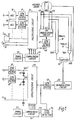
- the recording and reproducing system has thirty six discrete input channels. As shown in Figure 1, thirty two of these channels, I1, I2 .... I32, are available to receive analogue voice signals, another channel I36 receives a synchronisation signal, in the form of a fixed voltage level, and the three remaining input channels I33, I34and I35 enable ancillary functions to be performed, as will be described hereinafter.
- Each voice input channel I1, I2 .... I32 comprises the series arrangement of an automatic gain control (AGC) circuit 10 and a low pass filter 11, and is connected to a respective input terminal of a time division multiplexing circuit 20 (a 74 HC 4051).
- AGC automatic gain control
- the low pass filters 11 are so chosen that the recording and reproducing system has a desired frequency response which, in this embodiment, is in the frequency range from 300 Hz to 3.4 kHz, the frequency range normally associated with voice signals.
- the automatic gain control circuits 10 exercise control over the amplitudes of the analogue voice signals supplied to the multiplexing circuit 20, being effective to confine the input voltage levels to a range of voltage bounded by an upper voltage level of +1 volt and a lower voltage level of -1 volt.
- the synchronisation signal on the other hand, which is supplied to the multiplexing circuit 20 via input channel I36, has a fixed voltage level which lies outside the afore-mentioned voltage range and which, in this embodiment, is set at -2 volts. In this way, the synchronsation signal in channel I36 is readily distinguishable from all the other input signals in channels I1, I2 .... I35.
- a commutator circuit 21 receives clock pulses from a timing circuit 22 and, in response thereto, causes the multiplexing circuit 20 to sample the analogue signals in the input channels cyclically, in a pre-arranged sequence. By this means, the voltage level in each channel is sampled once every 125»sec for a respective sampling period lasting 3.5»sec. The sampled voltage levels are output to a single output channel 40.
- Figure 2 illustrates the multiplexing format for one complete sampling cycle (hereinafter referred to as a "frame") lasting 125»sec.
- the first input channel to be sampled (during time slot "0") is channel I36 containing the synchronisation signal, giving rise to a voltage level of -2 volts in the output channel 40, as shown in Figure 2.
- Input channels I1, I2 .... I35 are then sampled during successive time slots (designated “1” to “35") in the pre-arranged sequence indicated by the channel numbers (1-35) in Figure 2.
- the voltage level which is output to channel 40 represents the voltage level prevailing in the respective input channel during the relevant sampling period.
- the voltage level supplied to output channel 40 during the corresponding time slots would be 0 volts.
- each voltage level in channel 40 represents a "snap-shot" of an analogue signal in the corresponding input channel during the respective sampling period.
- the input signals in channels I33, I34 and I35 consist of logic levels (either +1 volt or -1 volt) which comprise part of a time code signal, a test signal and a microphone signal respectively.
- the time code signals represent the actual time a recording was made and, similarly, the test signals and the microphone signals represent respectively, test data, which can be input to channel I35, and an audio message which can be recorded by an operator, as desired, via a microphone input 12 to channel I34.
- the sequence of voltage levels in channel 40 is supplied to a further low pass filter 41 which removes high frequency components lying outside the desired frequency range.
- the filtered signals are then passed to an FM modulation circuit 42 wherein they modulate a carrier signal preparatory to being recorded on magnetic tape.
- the modulated carrier signal is supplied simultaneously to a pair of record heads 43,44 forming part of a helical scan recording unit.
- the two record heads are mounted 180° apart at the circumference of a rotating drum relative to which the tape is transported.
- the two heads record tracks or swipes alternately.
- the swipes extend diagonally across the tape, as shown in Figure 3, the swipes recorded by one of the heads (43, say) being denoted as “Track A” swipes and the swipes recorded by the other head (44) being denoted as “Track B” swipes, interlaced with the "Track A” swipes.
- Each swipe contains 512 frames (lasting 64ms). However, as will be explained with reference to Figures 4a and 4b, additional frames are recorded at the ends of each swipe.
- the tape transport mechanism operates at a much lower speed than is used to record video signals and, in this way, it is possible to record continuously for 25 hours using a conventional E240 VHS (i.e. 8 hour) tape.
- neighbouring input channels e.g. channels 1,2; 3,4; etc.
- time slots (6,24; 15,33) which are separated in time by half the sampling period i.e 62.5»sec. Accordingly, therefore, by connecting such neighbouring channels in parallel it is possible to sample an analogue input signal at twice the normal rate, thereby enabling the bandwidth for the connected channels to be doubled.
- the same (or alternatively different) heads may be used to read the recorded signals.
- head 43 is used to read the 'Track A' swipes and head 44 is used to read the 'Track B' swipes.
- the output of each head 43,44 is connected to an FM demodulator circuit 52 via a respective preamplifier/equalizer circuit 50A,50B and a common switch circuit 51.
- the switch circuit is controlled by a track selection signal A/B from the drum and is effective to route the Track A signals (produced at the output of head 43) and the Track B signals (produced at the output of head 44) alternately to the FM demodulation circuit 52.
- the output of the demodulator circuit 52 is connected to a low pass filter 53, and a synchronisation level detection circuit 54 compares the amplitudes of the filtered signals with a suitable threshold level (set between -1 volt and -2 volts) whereby to detect the synchronisation signal which marks the start of each new frame (time slot "0" in Figure 2). Each time a synchronisation signal is detected, the detection circuit 54 generates a trigger signal V T effective to initialise a commutator circuit 55 associated with a time division de-multiplexing circuit 56.
- a suitable threshold level set between -1 volt and -2 volts
- the commutator circuit 55 receives clock signals from a timing circuit 57 and, in response thereto, causes the de-multiplexing circuit 56 to distribute, in the correct sequence, the voltage levels (in time slots 1 to 35) which follow the synchronisation signal to respective ones of a plurality of output channels O1, O2 .... O36, each corresponding to a respective input channel I1, I2 .... I36, whereby to reproduce the recorded signals.
- Each output channel comprises the series arrangement of a sample and hold (S/H) circuit 60 and a low pass filter 61.
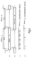
- Figures 4(a) and 4(b) illustrate diagrammatically the variations in time of the envelopes of signals recorded in successive swipes and, as before, the regions where duplication occurs are referenced 'd'.
- Figures 4(c) and 4(d) illustrated, on an expanded time scale, the relative timing of corresponding synchronisation signals derived from regions referenced 'd' in Figures 4(a) and 4(b) respectively.
- the synchronisation signals derived from the Track B swipe are shifted in time relative to the corresponding synchronisation signals derived from the Track A swipe. It will be appreciated that the synchronisation signals derived from one swipe (in Track A, say) could either precede or succeed in time the corresponding synchronisation signals derived from the adjacent swipe (in Track B).
- the recording consists of audio signals such instantaneous time disruptions, although undesirable, could perhaps be tolerated.
- the afore-mentioned time disruptions would compromise the operational integrity of the recording system.
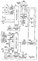
- the recording system shown in Figure 5 incorporates a modification of the system of Figure 1.
- Some of the components used in the modified system are identical to those used in the system of Figure 1, and these have been ascribed like reference numerals.
- the modified system incorporates a phase-locked loop which, in effect, averages over time the synchronisation signals derived from both the Track A and the Track B swipes and generates a new sequence of psuedo synchronisation signals. These psuedo synchronisation signals are used to control the relative timings of the demultiplexed signals output from both tracks of the recording system in order to remove any instantaneous time disruptions that may be present.
- the Track A/Track B output signals are demodulated and demultiplexed separately.
- the output signals from each read head 43,44 are routed via a respective pre-amplifier/equaliser circuit 50A,50B to a respective FM demodulation circuit 52A,52B.
- the output of each demodulation circuit is connected to a respective low pass filter 53A,53B and a respective synchronisation level detection circuit 54A,54B compares the amplitudes of the filtered signals with a suitable threshold level (between -1 volt and -2 volts) whereby to detect the synchronistion signals which mark the start of each new frame in the respective track.
- the detection circuit 54A,54B Each time a synchronisation signal is detected, the detection circuit 54A,54B generates a trigger signal V TA ,V TB effective to initialise a respective commutator circuit 55A,55B.
- the commutator circuits receive clock signals from respective timing circuits 57A,57B and, in response thereto, cause associated time division de-multiplexing circuits 56A,56B to distribute the voltage levels (in time slots 1 to 35) which follow each detected synchronisation signal to respective sample and hold circuits 60A(1), 60A(2) Vietnamese 60A(36); 60B(1), 60B(2) Vietnamese .
- the trigger signals V TA ,V TB from both tracks are supplied to a phase-locked loop 70 which, as explained, effectively averages the synchronisation signals detected in Tracks A and B and generates a new sequence of psuedo synchronisation signals Sp.
- These signals are supplied to a time base correction (TCB) address generator 71 which generates 72 TCB addresses, each controlling the state of a respective switch 61A(1),61A(2) ?? 61A(36); 61B(1), 61B(2) .... 61B(36) connected in series with a respective one of the sample and hold circuits.
- TCB time base correction
- the relative timings of the psuedo synchronisation signals, and so of the TCB addresses, are such that any instantaneous time disruptions which may have been present in the demultiplexed signals are removed before the signals are output from channels O1, O2 ... O36 via the switches and respective low pass filters 62.
- a logic circuit 72 is provided to recognise the first few (typically two) synchronisation pulses in each swipe and to cause the address generator 71 to switch from one bank of addresses, appropriate for the current swipe (a Track A swipe, say) to the other bank of addresses, appropriate for the next swipe (a Track B swipe).
- the logic circuit is also arranged to ignore any remaining synchronisation pulses in the current swipe so as to prevent the address generator from switching back prematurely.
Landscapes
- Engineering & Computer Science (AREA)
- Signal Processing (AREA)
- Signal Processing For Digital Recording And Reproducing (AREA)
- Television Signal Processing For Recording (AREA)
- Signal Processing Not Specific To The Method Of Recording And Reproducing (AREA)
Claims (7)
- Aufzeichnungs- und Wiedergabesystem, umfassend
eine Vielzahl von individuellen Eingangskanälen (I₁ ... I₃₆) zum Empfangen von entsprechenden, entsprechende Pegel aufweisenden Eingangssignalen;
Zeitteilermultiplexmittel (20) zum zyklischen Abtasten der entsprechenden Eingangssignale gemäß einer vorbestimmten Sequenz der Eingangskanäle (I₁ ... I₃₆) und zum Ausgeben einer Folge von entsprechende Zeitschlitze einnehmenden Abtastungen, wobei jede Abtastung einen Pegel eines in einem entsprechenden Eingangskanal (I₁ ... I₃₆) während eines entsprechenden Zeitschlitzes empfangenen Eingangssignals darstellt,
Frequenzmodulationsmittel (42) zum Frequenzmodulieren der Folge von durch die Zeitteilermultiplexmittel (22) ausgegebenen Abtastungen, um frequenzmodulierte Abtastungen zu erzeugen;
Mittel (43,44) zum Aufzeichnen der frequenzmodulierten Abtastungen als ein Analogsignal auf magnetischem Aufzeichnungsband;
Mittel (43,44) zum Wiedergeben der frequenzmodulierten Abtastungen von dem magnetischen Aufzeichnungsband;
Frequenzdemodulationsmittel (52) zum Demodulieren der frequenzmodulierten, durch das Wiedergabemittel (43,44) wiedergegebene Abtastungen, um eine Folge von frequenzmodulierten Abtastungen zu erzeugen;
eine Vielzahl von Ausgangskanälen (O₁ ... O₃₆), wobei jeder Ausgangskanal einem entsprechenden Eingangskanal entspricht;
Zeitteilerdemultiplexmittel (56) zum Verteilen der frequenzdemodulierten, von dem Frequenzdemodulationsmittel abgegebenen Abtastungen zu entsprechenden Ausgangskanälen (O₁ ... O₃₆) und Synchronisationsignaldetektionsmittel (54),
dadurch gekennzeichnet, daß die von einem der Eingangskanäle (I₃₆) erhaltenen Abtastungen als Synchronisationssignale verwendet werden, wobei das Synchronisationsignaldetektionsmittel (54) die frequenzdemodulierten Abtastungen entsprechend zu den Abtastungen detektiert, die als Synchronisationssignale verwendet werden, und das Zeitteilerdemultiplexmittel (56) die frequenzdemodulierten, von besagtem Frequenzdemodulationsmittel (52) zu entsprechenden Ausgangskanälen (O₁ ... O₃₆) in Übereinstimmung mit der zeitlichen Zuordnung der Synchronisationssignale ausgegebenen Abtastungen verteilt. - Aufzeichnungs- und Wiedergabesystem wie in Anspruch 1 beansprucht, bei dem die als Synchronisationssignale verwendeten Abtastungen einen Pegel größer als derjenige irgendeiner anderen Abtastung besitzen.
- Aufzeichnungs- und Wiedergabesystem wie in Anspruch 1 oder Anspruch 2 beansprucht, bei dem wenigstens einer der Eingangskanäle (I₁ ... I₃₆) ein auf Frequenzen im Bereich von 300 Hz ... 3,4 kHz ansprechendes Tiefpassfilter (11) einschließt.
- Aufzeichnungs- und Wiedergabesystem wie in einem der Ansprüche 1 bis 3 beansprucht, bei dem besagtes Zeitteilermultiplexmittel (20) einen Abtastzyklus vorbestimmter Periode besitzt und das Zeitteilermultiplexmittel (20) die in physikalisch benachbarten besagter Eingangskanäle zu entsprechenden Zeiten während besagten Abtastzyklus empfangenen Eingangssignale abtastet, die zeitlich durch die halbe vorbestimmte Periode getrennt sind.
- Aufzeichnungs- und Wiedergabesystem wie in einem der Ansprüche 1 bis 4 beansprucht, bei dem besagtes Aufzeichnungs- und Wiedergabemittel (43,44) zwei Aufnahme-/Wiedergabeköpfe zum Aufzeichnen der frequenzmodulierten Abtastungen auf und zum Wiedergeben der aufgezeichneten Abtastungen von entsprechenden spiralförmigen Spuren auf Magnetband umfaßt und Mittel (70,71) zum Ableiten von zusätzlichen Synchronisationssignalen von entsprechenden in beiden spiralförmigen Spuren aufgezeichneten Synchronisationssignalen und zum Nutzen der zusätzlichen Synchronisationssignale zum Kontrollieren des Ausgangs der frequenzdemodulierten Abtastungen von den Ausgangskanälen (O₁ ... O₃₆) einschließt.
- Aufzeichnungs- und Wiedergabesystem wie in Anspruch 5 beansprucht, umfassend ein entsprechendes Zeitteilerdemultiplexmittel (56A, 56B), jedes auf durch den entsprechenden Kopf (43,44) aufgezeichnete Synchronisationssignale ansprechend, um die frequenzdemodulierten, durch diesen Kopf wiedergegebenen Abtastungen auf entsprechende Ausgangskanäle (O₁ ... O₃₆) zu verteilen.
- Aufzeichnungs- und Wiedergabesystem wie in Anspruch 5 oder Anspruch 6 beansprucht, bei dem besagtes Mittel (70,71) zum Ableiten besagter zusätzlicher Synchronisationssignale eine phasensynchronisierte Schleife (70) einschließt, an die die in beiden besagten spiralförmigen Abtastspuren aufgezeichneten Synchronisationssignale gegeben werden.
Applications Claiming Priority (2)
| Application Number | Priority Date | Filing Date | Title |
|---|---|---|---|
| GB909000105A GB9000105D0 (en) | 1990-01-03 | 1990-01-03 | Recording system |
| GB9000105 | 1990-01-03 |
Publications (3)
| Publication Number | Publication Date |
|---|---|
| EP0439903A2 EP0439903A2 (de) | 1991-08-07 |
| EP0439903A3 EP0439903A3 (en) | 1992-05-20 |
| EP0439903B1 true EP0439903B1 (de) | 1995-06-28 |
Family
ID=10668799
Family Applications (1)
| Application Number | Title | Priority Date | Filing Date |
|---|---|---|---|
| EP90311274A Expired - Lifetime EP0439903B1 (de) | 1990-01-03 | 1990-10-15 | Aufzeichnungs- und Wiedergabesystem |
Country Status (6)
| Country | Link |
|---|---|
| US (1) | US5353168A (de) |
| EP (1) | EP0439903B1 (de) |
| JP (1) | JPH03256264A (de) |
| DE (1) | DE69020532T2 (de) |
| GB (1) | GB9000105D0 (de) |
| HK (1) | HK159195A (de) |
Cited By (1)
| Publication number | Priority date | Publication date | Assignee | Title |
|---|---|---|---|---|
| CN105604539A (zh) * | 2014-11-24 | 2016-05-25 | 核工业北京地质研究院 | 多参数组合测井探管 |
Families Citing this family (21)
| Publication number | Priority date | Publication date | Assignee | Title |
|---|---|---|---|---|
| CA2128835C (en) * | 1993-08-03 | 1999-04-06 | Daniel F. Daly | Modular digital recording logger |
| GB9620082D0 (en) | 1996-09-26 | 1996-11-13 | Eyretel Ltd | Signal monitoring apparatus |
| US6775372B1 (en) | 1999-06-02 | 2004-08-10 | Dictaphone Corporation | System and method for multi-stage data logging |
| US6252947B1 (en) * | 1999-06-08 | 2001-06-26 | David A. Diamond | System and method for data recording and playback |
| US6249570B1 (en) * | 1999-06-08 | 2001-06-19 | David A. Glowny | System and method for recording and storing telephone call information |
| US6252946B1 (en) * | 1999-06-08 | 2001-06-26 | David A. Glowny | System and method for integrating call record information |
| US6246752B1 (en) | 1999-06-08 | 2001-06-12 | Valerie Bscheider | System and method for data recording |
| WO2002016993A1 (en) * | 2000-08-18 | 2002-02-28 | Nikon Corporation | Optical element holding device |
| US6782091B1 (en) | 2000-10-13 | 2004-08-24 | Dunning Iii Emerson C | Virtual call distribution system |
| WO2003074326A1 (en) | 2002-03-07 | 2003-09-12 | Nice Systems Ltd. | Method and apparatus for internal and external monitoring of a transportation vehicle |
| US7546173B2 (en) | 2003-08-18 | 2009-06-09 | Nice Systems, Ltd. | Apparatus and method for audio content analysis, marking and summing |
| US7714878B2 (en) | 2004-08-09 | 2010-05-11 | Nice Systems, Ltd. | Apparatus and method for multimedia content based manipulation |
| US8724891B2 (en) * | 2004-08-31 | 2014-05-13 | Ramot At Tel-Aviv University Ltd. | Apparatus and methods for the detection of abnormal motion in a video stream |
| US8078463B2 (en) * | 2004-11-23 | 2011-12-13 | Nice Systems, Ltd. | Method and apparatus for speaker spotting |
| US8005675B2 (en) | 2005-03-17 | 2011-08-23 | Nice Systems, Ltd. | Apparatus and method for audio analysis |
| US10019877B2 (en) | 2005-04-03 | 2018-07-10 | Qognify Ltd. | Apparatus and methods for the semi-automatic tracking and examining of an object or an event in a monitored site |
| US7386105B2 (en) | 2005-05-27 | 2008-06-10 | Nice Systems Ltd | Method and apparatus for fraud detection |
| WO2007086042A2 (en) | 2006-01-25 | 2007-08-02 | Nice Systems Ltd. | Method and apparatus for segmentation of audio interactions |
| US7631046B2 (en) | 2006-10-26 | 2009-12-08 | Nice Systems, Ltd. | Method and apparatus for lawful interception of web based messaging communication |
| US8571853B2 (en) | 2007-02-11 | 2013-10-29 | Nice Systems Ltd. | Method and system for laughter detection |
| US7599475B2 (en) | 2007-03-12 | 2009-10-06 | Nice Systems, Ltd. | Method and apparatus for generic analytics |
Family Cites Families (12)
| Publication number | Priority date | Publication date | Assignee | Title |
|---|---|---|---|---|
| US3889293A (en) * | 1973-03-05 | 1975-06-10 | Us Navy | Radar recording and reproducing system with pulse modulation and time division multiplexing |
| US4437128A (en) * | 1980-12-02 | 1984-03-13 | Manfred Fred Honeck | System and method of recording and reproducing wide band channel information by means of several narrow band channels |
| JPS57152506A (en) * | 1981-03-16 | 1982-09-20 | Victor Co Of Japan Ltd | Magnetic recording system |
| GB2125655A (en) * | 1982-08-13 | 1984-03-07 | Oxford Med Syst | Apparatus and methods for multi-channel signal recording |
| US4575773A (en) * | 1982-11-04 | 1986-03-11 | Dymond Anthony M | Method and apparatus for selectively recording instrument quality data or composite instrument quality data and video signals on a commercial unmodified video tape recorder |
| JPS59188878A (ja) * | 1983-04-11 | 1984-10-26 | Olympus Optical Co Ltd | 放送内容記録再生装置 |
| JPS6059503A (ja) * | 1983-09-09 | 1985-04-05 | Sharp Corp | 磁気記録再生装置 |
| JPS60133570A (ja) * | 1983-12-21 | 1985-07-16 | Sharp Corp | 磁気記録再生装置 |
| JPS60199283A (ja) * | 1984-03-24 | 1985-10-08 | Sony Corp | 磁気記録再生装置 |
| JPH0690826B2 (ja) * | 1985-04-05 | 1994-11-14 | ソニー株式会社 | 信号再生装置 |
| JPS62233990A (ja) * | 1986-04-03 | 1987-10-14 | Matsushita Electric Ind Co Ltd | 映像信号記録再生方法 |
| US5036409A (en) * | 1989-03-15 | 1991-07-30 | Deutsche Thomson-Brandt Gmbh | Signal selection arrangement |
-
1990
- 1990-01-03 GB GB909000105A patent/GB9000105D0/en active Pending
- 1990-10-15 EP EP90311274A patent/EP0439903B1/de not_active Expired - Lifetime
- 1990-10-15 DE DE69020532T patent/DE69020532T2/de not_active Expired - Fee Related
- 1990-10-18 JP JP2277919A patent/JPH03256264A/ja active Pending
-
1992
- 1992-11-05 US US07/972,080 patent/US5353168A/en not_active Expired - Fee Related
-
1995
- 1995-10-12 HK HK159195A patent/HK159195A/en not_active IP Right Cessation
Cited By (1)
| Publication number | Priority date | Publication date | Assignee | Title |
|---|---|---|---|---|
| CN105604539A (zh) * | 2014-11-24 | 2016-05-25 | 核工业北京地质研究院 | 多参数组合测井探管 |
Also Published As
| Publication number | Publication date |
|---|---|
| EP0439903A2 (de) | 1991-08-07 |
| GB9000105D0 (en) | 1990-03-07 |
| JPH03256264A (ja) | 1991-11-14 |
| DE69020532T2 (de) | 1996-03-14 |
| DE69020532D1 (de) | 1995-08-03 |
| HK159195A (en) | 1995-10-20 |
| EP0439903A3 (en) | 1992-05-20 |
| US5353168A (en) | 1994-10-04 |
Similar Documents
| Publication | Publication Date | Title |
|---|---|---|
| US5353168A (en) | Recording and reproducing system using time division multiplexing | |
| US5132807A (en) | Recording apparatus for recording main information with additional information | |
| US5023707A (en) | System for combining multiple audio channels into the baseband video signal and the recovery of the audio channels therefrom | |
| EP0080297B1 (de) | Magnetbandaufzeichnungs- und Wiedergabeanordnung | |
| US4479150A (en) | Methods and arrangements for changing the audio information in an audio/video recording/reproduction system | |
| US4772960A (en) | Apparatus for recording and/or reproducing an information signal comprised of at least an audio signal and an index signal | |
| US4758904A (en) | Apparatus for recording and/or reproducing an additional information signal | |
| CA1209695A (en) | Recording and/or reproducing apparatus | |
| KR950003632B1 (ko) | 영상 재생 장치 | |
| EP0209151B1 (de) | Gerät zum Aufzeichnen und/oder zur Wiedergabe eines Informationssignals | |
| CA1291258C (en) | Recording and/or reproducing apparatus | |
| EP0465103B1 (de) | Videoband-Wiedergabegerät | |
| EP0473417A2 (de) | Vorrichtungen zur Wiedergabe von digitalen Signalen | |
| US5432649A (en) | Magnetic recording and reproducing apparatus | |
| US5251075A (en) | Cue signal detecting apparatus | |
| US5428485A (en) | Video tape recorder with PCM audio recording with device for detecting irregularities in the video signal | |
| US5181125A (en) | Apparatus for muting noise resulting from reproducing of a PCM audio signal recorded in an extension of a slant track containing a recorded video signal | |
| JP2698383B2 (ja) | 情報信号記録装置及び再生装置 | |
| JPS60111369A (ja) | 記録再生装置 | |
| JP3152032B2 (ja) | 磁気記録再生装置 | |
| JPS6223512B2 (de) | ||
| KR910002346B1 (ko) | 모노/멀티트랙(mono/multi track) 전환회로 | |
| JPS60131662A (ja) | 記録モ−ド判別方法 | |
| JPH0273790A (ja) | 磁気記録再生装置 | |
| JPS60106076A (ja) | 補助トラツク上への多重化デ−タ記録再生方式 |
Legal Events
| Date | Code | Title | Description |
|---|---|---|---|
| PUAI | Public reference made under article 153(3) epc to a published international application that has entered the european phase |
Free format text: ORIGINAL CODE: 0009012 |
|
| AK | Designated contracting states |
Kind code of ref document: A2 Designated state(s): DE FR GB IT |
|
| PUAL | Search report despatched |
Free format text: ORIGINAL CODE: 0009013 |
|
| AK | Designated contracting states |
Kind code of ref document: A3 Designated state(s): DE FR GB IT |
|
| 17P | Request for examination filed |
Effective date: 19920828 |
|
| 17Q | First examination report despatched |
Effective date: 19940711 |
|
| GRAA | (expected) grant |
Free format text: ORIGINAL CODE: 0009210 |
|
| AK | Designated contracting states |
Kind code of ref document: B1 Designated state(s): DE FR GB IT |
|
| REF | Corresponds to: |
Ref document number: 69020532 Country of ref document: DE Date of ref document: 19950803 |
|
| ITF | It: translation for a ep patent filed | ||
| ET | Fr: translation filed | ||
| PLBE | No opposition filed within time limit |
Free format text: ORIGINAL CODE: 0009261 |
|
| STAA | Information on the status of an ep patent application or granted ep patent |
Free format text: STATUS: NO OPPOSITION FILED WITHIN TIME LIMIT |
|
| 26N | No opposition filed | ||
| PGFP | Annual fee paid to national office [announced via postgrant information from national office to epo] |
Ref country code: GB Payment date: 19961007 Year of fee payment: 7 |
|
| PGFP | Annual fee paid to national office [announced via postgrant information from national office to epo] |
Ref country code: FR Payment date: 19961009 Year of fee payment: 7 |
|
| PGFP | Annual fee paid to national office [announced via postgrant information from national office to epo] |
Ref country code: DE Payment date: 19961018 Year of fee payment: 7 |
|
| PG25 | Lapsed in a contracting state [announced via postgrant information from national office to epo] |
Ref country code: GB Free format text: LAPSE BECAUSE OF NON-PAYMENT OF DUE FEES Effective date: 19971015 |
|
| PG25 | Lapsed in a contracting state [announced via postgrant information from national office to epo] |
Ref country code: FR Free format text: THE PATENT HAS BEEN ANNULLED BY A DECISION OF A NATIONAL AUTHORITY Effective date: 19971031 |
|
| GBPC | Gb: european patent ceased through non-payment of renewal fee |
Effective date: 19971015 |
|
| PG25 | Lapsed in a contracting state [announced via postgrant information from national office to epo] |
Ref country code: DE Free format text: LAPSE BECAUSE OF NON-PAYMENT OF DUE FEES Effective date: 19980701 |
|
| REG | Reference to a national code |
Ref country code: FR Ref legal event code: ST |
|
| PG25 | Lapsed in a contracting state [announced via postgrant information from national office to epo] |
Ref country code: IT Free format text: LAPSE BECAUSE OF NON-PAYMENT OF DUE FEES;WARNING: LAPSES OF ITALIAN PATENTS WITH EFFECTIVE DATE BEFORE 2007 MAY HAVE OCCURRED AT ANY TIME BEFORE 2007. THE CORRECT EFFECTIVE DATE MAY BE DIFFERENT FROM THE ONE RECORDED. Effective date: 20051015 |