EP0439925A2 - Maximalwahrscheinlichkeitsdekodierung mit Störungsdetektion für Frequenzsprungsysteme mit kodierter Modulation - Google Patents
Maximalwahrscheinlichkeitsdekodierung mit Störungsdetektion für Frequenzsprungsysteme mit kodierter Modulation Download PDFInfo
- Publication number
- EP0439925A2 EP0439925A2 EP90312937A EP90312937A EP0439925A2 EP 0439925 A2 EP0439925 A2 EP 0439925A2 EP 90312937 A EP90312937 A EP 90312937A EP 90312937 A EP90312937 A EP 90312937A EP 0439925 A2 EP0439925 A2 EP 0439925A2
- Authority
- EP
- European Patent Office
- Prior art keywords
- signal points
- interference
- transmitted
- coded modulation
- received
- Prior art date
- Legal status (The legal status is an assumption and is not a legal conclusion. Google has not performed a legal analysis and makes no representation as to the accuracy of the status listed.)
- Granted
Links
Images



Classifications
-
- H—ELECTRICITY
- H04—ELECTRIC COMMUNICATION TECHNIQUE
- H04B—TRANSMISSION
- H04B1/00—Details of transmission systems, not covered by a single one of groups H04B3/00 - H04B13/00; Details of transmission systems not characterised by the medium used for transmission
- H04B1/69—Spread spectrum techniques
- H04B1/713—Spread spectrum techniques using frequency hopping
- H04B1/715—Interference-related aspects
-
- H—ELECTRICITY
- H04—ELECTRIC COMMUNICATION TECHNIQUE
- H04L—TRANSMISSION OF DIGITAL INFORMATION, e.g. TELEGRAPHIC COMMUNICATION
- H04L27/00—Modulated-carrier systems
- H04L27/18—Phase-modulated carrier systems, i.e. using phase-shift keying
- H04L27/186—Phase-modulated carrier systems, i.e. using phase-shift keying in which the information is carried by both the individual signal points and the subset to which the individual signal points belong, e.g. coset coding or related schemes
Definitions
- the present invention relates to local area networks (LANs) and, more particularly, to wireless LANs.
- LANs local area networks
- wireless LANs wireless LANs
- frequency hopping is a technique in which the information to be communicated is transmitted over a sequence of predefined "hopping" frequencies in a predefined order.
- the underlying theory of this approach is that loss and fading are not likely to occur over all frequencies at the same time.
- channel coding may be used in conjunction with the frequency hopping in such a way that the lost information can be recovered with high probability.
- the information is encoded into a sequence of codewords, each codeword being made up of a sequence of signal points.
- the number of signal points in each codeword is the same as the number of hopping frequencies, and the signal points are rearranged for transmission in such a way that each signal point from each codeword is transmitted on a respective different hopping frequency.
- the inherent redundancy in the coding is such that, as noted above, the lost information can be recovered with high probability.
- an interleaving approach may be used in which data signal points from a number of sequential codewords are transmitted on a single hopping frequency before transmission proceeds to the next hopping frequency. This advantageously reduces the rate at which the system needs to switch from one hopping frequency to another.
- the present invention is directed to a frequency hopping transmission technique which is particularly useful in environments in which strong interference is expected, such as the so-called ISM band allocated by the United States Federal Communications Commission.
- a technique for detecting strong interference in conjunction with a) coded modulation with built-in diversity and b) soft decision decoding can, indeed, provide a system which combats both fading and strong interference to an extent not achieved heretofore.
- the diversity-coded modulation provides protection against fading.
- the effectiveness of coding techniques is reduced in the presence of strong interference.
- the interference detection technique provides the needed interference immunity and thereby overcomes this limitation of the codes themselves.
- the preferred approach to detecting the likelihood of strong interference is to transmit the modulated signal in such a way that the interference will cause the received signal to have a particular characteristic which can be detected. More particularly, in preferred embodiments a predetermined interference-detection sequence of signal points known at both the transmitter and receiver is transmitted along with the sequence of diversity-coded data signal points over each hopping frequency, and the error rate of the received interference-detection signal points is the aforementioned particular characteristic. If the number of such errors is below a certain threshold, no strong interference has occurred and decoding proceeds normally. On the other hand, if the interference-detection signal points are substantially in error, strong interference is assumed to have occurred. In that case, the decoding process itself proceeds normally but the values of the received signal points as applied to the decoder are set to zero (or, equivalently, are simply ignored).
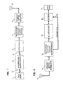
- FIG. 1 is a block diagram of a transmitter embodying the principles of the invention.
- the transmitter is illustratively a part of a wireless local area network (LAN) which can be used, for example, to interconnect a collection of terminals, such as PCs, printers, file servers and the like, which are located within a localized environment, such as an office building.
- LAN wireless local area network
- the LAN could be used as the interconnection mechanism for a wireless communication system, such as a PBX.
- Radio signals generated by the transmitter are received by a receiver, shown in FIG. 2, which is within the geographical area covered by the LAN.
- Block encoder/mapper 13 accumulates a block of input data comprised of N signalling intervals' worth of bits and then uses a particular 2N-dimensional block code to encode the accumulated N x m bits into N groups of (m+r) encoded bits, those groups being provided successively on leads 15.
- the parameter r is the average number of redundant bits per signalling interval introduced by the block encoder/mapper 13.
- Each allowed bit pattern of the (m+r)-bit group is associated with a particular signal point of a two-dimensional (2D) M( ⁇ 2 m+r )-PSK constellation.
- the block code is referred to as being "2N-dimensional" because each signal point has 2 dimensions and each "codeword" output by the block encoder/mapper 13 is represented by N signal points.
- the 2N-dimensional block encoder/mapper generates 2N-dimensional "codewords".
- Each codeword is comprised of a block of N coded modulation "signal points".
- Each signal point is a point in a predetermined two-dimensional "constellation"--illustratively shown in FIG. 7 as a phase shift keying constellation having four signal points, or 4-PSK.
- This 2N-dimensional codeword is delivered during N "signalling intervals," one signal point in each signalling interval.
- the assemblage of all 2N-dimensional codewords is referred to as the "2N-dimensional constellation," with each codeword being an "element" of the 2N-dimensional constellation.
- the 2N-dimensional constellation is also referred to as a codebook or as an alphabet.
- the code is constructed in such a way, as described below, as to have so-called built-in diversity.
- this diversity is exploited by the use of frequency hopping transmission in which at least particular signal points of a codeword--those which exhibit the diversity--are transmitted using different transmission frequencies. These frequencies are sufficiently spaced apart to ensure that they fade independently, thereby taking advantage of the diversity built into the code.
- the signal points output by encoder/mapper 13 are thereafter rearranged by interleaver 16 in order to reduce the rate at which the system needs to switch from one hopping frequency to another, as will also be further described.
- the interleaved signal points are thereupon operated on by interference-detection-sequence inserter 19 which, as its name implies, combines a predetermined sequence of interference-detection signal points with the interleaved data signal points in a deterministic way. This sequence of interference-detection signal points is used later, in the receiver, to identify the likely occurrence of interference whose strength is comparable to, or even stronger than, the transmitted signal.
- the resulting combined signal point stream at the output of inserter 19 is then passed to frequency hopping modulator 21, which modulates the signal points--illustratively using M-ary PSK--and applies the resulting radio signal to antenna 23.
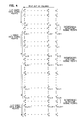
- FIG. 3 shows one possible way in which the coded data signal points are interleaved and the interference-detection sequence is combined therewith.
- the N signal points of the i th codeword are denoted S 1 i , S 2 i , ..., S N i .
- Q such codewords are read into interleaver 16 and may be thought of as being stored in rows.
- Each of the N interference-detection sequences may be identical to one another.
- N 8.
- Q is illustratively on the order of a few hundreds and K is on the order of 10-30.
- Inserter 19 operates in such a way as to provide to modulator 21 a first sequence comprised of interference-detection signal points and coded data signal points to be transmitted using frequency f1, another such sequence to be transmitted using frequency f2, and so forth for each of the N frequencies.
- This process may be conceptualized, as shown in FIG. 3, as reading out the columns of signal points and transmitting the signal points from each column using a respective frequency.
- inserter 19 outputs to modulator 21, for transmission using frequency f1, the sequence of K interference-detection signal points, P 1 1 , P 1 2 , ...,P 1 K .
- interference-detection signal points can be included in the transmitted signal point stream in the form of a preamble as just described, it is preferred, in accordance with a feature of the invention, to distribute the interference-detection signal points among the coded data signal points transmitted on each frequency so that they are transmitted non-time-contiguously. This distributed approach provides improved performance over the preamble approach, as will be described in further detail hereinbelow.
- FIG. 4 A conceptual view of the distributed approach is provided in FIG. 4.
- the codewords can be thought of as being read into the interleaver and stored therein in rows.
- the K rows of interference-detection signal points are interspersed among the Q rows of data signal points, rather than being grouped together as in FIG. 3.
- the sequence of signal points transmitted on each frequency is comprised of K groups, each group being comprised of L 2 coded data signal points, one interference-detection signal point, and then another L 2 coded data signal points.
- the transmitted signal received at antenna 51, is applied to frequency hopping demodulator 54, which hops in synchronism with modulator 21.
- Demodulator 54 generates a stream of noisy received signal points corresponding to the transmitted signal points output by inserter 19.
- This stream of received signal points is passed to interference-detection sequence checker/remover 56, which makes a so-called "hard" decision for each received interference-detection signal point, i.e., chooses the point of the M-PSK constellation that is closest to the received point and compares it to the transmitted such signal point which is known, a priori, at the receiver.
- the number of interference-detection signal points in error is counted for each sequence and the count is used as a mechanism for identifying signal points that are likely to have been subject to strong interference. If the number of errors is above a predetermined threshold, it is assumed that the transmitted signal was subjected to strong interference and, in this case, the occurrence of strong interference is declared by raising an erasure flag on lead 57--that flag to be used by decoder 61 as hereinafter described. If the number of errors is not above the predetermined threshold, no strong interference is assumed to have occurred and the erasure flag is not raised. In summary, then, the erasure flag is a signal indicative of the presence of strong interference in the block of coded modulation signal points transmitted over a given frequency, which signal is generated as a function of the error rate of the associated received interference-detection signal points.
- the principal reason for preferably distributing the interference-detection signal points among the coded data signal points transmitted on each frequency can now be understood. If the preamble approach were to be used, and if an interference event were to occur after the preamble had been transmitted, the erasure flag would not be raised, even though an interference event affecting the coded data signal points had occurred. By contrast, the distributed approach allows the receiver to raise the erasure flag at any point during the signal point sequence received at a given frequency--thereby enhancing the performance of the technique as a whole.
- Checker/remover 56 thereupon removes the information corresponding to the interference-detection signal points and passes the remaining part--corresponding to the coded data signal points--to de-interleaver 58.
- the latter performs the inverse operation of interleaver 16 so as to deliver to decoder 61 the signal points corresponding to the transmitted coded data signal points in the order in which those signal points were generated by encoder 13, i.e., in sequences of N-signal-point codewords.
- Decoder 61 attempts to recover the original binary data provided by data source 11, which it provides to data sink 71.
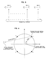
- FIG. 6 A 4-level, PSK (4-PSK) modulation scheme is assumed in which the nominal received signal points are the points A, B, C and D. Assume, now, that point A was transmitted but that, due to a fade in the transmission channel, the received signal is attenuated so that the received point is point F. Note that although the amplitude of the signal point is substantially reduced, the phase information has not been affected. This being so, it is advantageous to use the position of point F as input to the decoding process because there is still some correlation between the signal point positions of the transmitted and received signal points.
- the received signal point is now the point E, whose position bears little if any information about the transmitted point.
- the decoder it would be better for the decoder to assume a neutral posture and allow for the possibility that any of the four points A, B, C or D was transmitted, rather than to be biased with wholly erroneous information, which in this case would tend to bias the decoder toward point B.
- the erasure flag on lead 57 is generated with just such considerations in mind. Note that as long as a fade is not very deep (i.e., the received signal point is not very close to the origin in FIG. 6) additive noise will not change the complex signal plane quadrant of very many of the transmitted points. Accordingly, checker/remover 56 will make few (hard-decision) interference-detection signal point errors. Thus, as desired, a fade event is not likely to cause the erasure flag to be raised and decoder 61 will proceed to use the actual received signal points in its normal decoding process.
- decoder 61 will ignore those signal points received in time proximity to the interference event. That is, it will perform its decisions as to the values of the transmitted coded modulation signal points independently of the received values of those signal points that were subject to the strong interference.
- a 4-PSK signal constellation is illustratively used in implementing a 8-dimensional (8D) code, meaning that each codeword generated by the code is comprised of four 2D points of the 4-PSK constellation.
- This code is referred to herein as "Code I”. Those points are transmitted in respective signalling intervals.
- the four points of the constellation are labelled 0 through 3.
- the parameters m, r and N have values 11 ⁇ 2, 1 ⁇ 2 and 4, respectively.
- block encoder/mapper 13 generates a 2-bit pair in each of four successive signalling intervals, each such pair identifying, by its bit values, a particular one of the signal points 0 through 3.
- FIGS. 9 and 10 A graphical representation of the code is shown in FIGS. 9 and 10.
- a constituent 4D 4-PSK constellation which is formed by concatenating a pair of 2D 4-PSK constellations of the type shown in FIG. 8.
- An 8D constellation is then formed by selecting particular elements from a concatenated pair of the 4D constellations.
- Each element of the 8D constellation is a sequence of four 2D signal points and is a codeword of the 8D code.
- the concatenation of a particular pair of 4D elements is an element of the 8D constellation if and only if the pair of 4D subsets to which the first and second 4D elements belong respectively is one of the four patterns shown in FIG. 10.
- (0,1,1,2) is a codeword of the 8D code because a) (0,1) and (1,2) are elements of 4D subsets S1 and S2, respectively, and b) the pattern (S1,S2) is one of the four allowed patterns of 4D-subset pairs.
- (0,1,0,1) is not a codeword of the 8D code because a) (0,1) is an element of subset S1 and b) the pattern (S1,S1) is not one of the four allowed patterns of 4D-subset pairs.
- FIGS. 9-10 show one possible way in which two of the six bits are first used to select one of four 4D subset pairs from FIG. 10 and then two bits to select one of the four pairs of 2D signal points from one of the selected 4D subsets and likewise for the other selected 4D subset, for a total of six bits overall.
- each of the 8D codewords differs from any other 8D codewords in at least two signal point positions.
- the two 8D codewords (0,1,1,2) and (0,1,2,0) differ in the third and fourth signal point positions.
- the significance of this property may be understood by considering the case when one of the four constituent signal points is lost in transmission. It is nonetheless possible to recover that information as long as the other three constituent signal points of the 8D codeword have been accurately recovered.
- a code is said to have X-fold diversity, where X is an integer greater than unity, if each codeword, which is comprised of an ordered sequence of signal points, differs from each other codeword in at least X signal point positions.
- X is an integer greater than unity
- each codeword which is comprised of an ordered sequence of signal points, differs from each other codeword in at least X signal point positions.
- the above-described code has 2-fold built-in diversity.
- the larger the value of X the greater the so-called coding gain, which is measured by the savings in signal power over an uncoded modulation scheme.
- the signal points which provide the X-fold diversity should be transmitted in at least two--and preferably X--different frequencies which are sufficiently separated that they are likely to fade independently.
- the 2-fold diversity of the code may occur at any pair of signal point positions. That is, for any pair of signal point positions, there exists a pair of codewords which differ in exactly that pair of signal point positions.
- the four signal points of a codeword should be transmitted in four independently fading frequencies.
- MDX minimum squared Euclidean distance at X-fold time diversity
- a number of different 8D codes based on a 4-PSK constellation and having the same 2-fold diversity can alternatively be used in place of Code I.
- Such codes may be formed by, for example, partitioning the 16-element 4D constellation into various different groups of four subsets; by forming the 8D constellation by choosing various different 4D subset pairs. Any such codes are preferably constructed keeping in mind the desirability of being able to decode them simply using, for example, the soft-decision decoding technique described below.
- 2-fold built-in diversity such as is provided by the code just described may be regarded as inadequate to provide a given level of error performance.
- An advantageous way to achieve such a code is to build upon the 8D code--specifically by utilizing a 16D code (referred to as Code II)--in which each of the codewords is derived from a respective "base" codeword of the 8D code by simply repeating each signal point of the 8D codeword--referred to herein as "codeword repetition.”
- its MDX is 8.
- a code embodying codeword repetition can be constructed in which the signal points of the repeated codeword are not exactly the same as the base codeword but, rather, each signal point of the repeated codeword is mapped into a particular other signal point.
- the signal points 0,1,2 and 3 can be mapped into the signal points 0,2,1 and 3, respectively, so that the 16D codeword will be (0,1,1,2,0,2,2,1).
- An advantage of this approach is that the Euclidean distance between the codewords of the 16D code may be increased over that achieved by strictly repeating the base codeword.
- An additional alternative way of constructing a codeword repetition code is to concatenate each base codeword with another base codeword in a random fashion. This approach, however, will, in general, result in a code that is complex to decode.
- Code III-- Another possible code--referred to as Code III--is that depicted in the table of FIG. 11.
- This code exhibits greater error immunity than Code I due to its greater degree of diversity and greater MDX, but at a cost of a reduction in the data rate, e.g., two-thirds the rate of Code II.
- the code of FIG. 11 is comprised of 16 codewords, which are shown along with the 4-bit input patterns associated therewith.
- Each codeword is made up of a sequence of four 2D signal points from the 4-PSK constellation, those points, again, being identified as points 0,1,2 and 3.
- the 8D code of FIG. 11 was constructed by first constructing the 4D constellation made up of all sixteen possible pairs of the 2D signal points of the 2D constellation of FIG. 8. As before, the 4D constellation is then partitioned into subsets. In this case, there are 16 subsets, each having a single 4D element. Each of those 16 subsets may, therefore, be identified by its 4D element, viz., (0,0), (0,1), ..., (3,3).
- the 8D constellation is then formed by selecting 16 of the 256 possible 4D subset pairs.
- (0,2,3,1) is an 8D codeword formed by concatenating the two 4D subsets (0,2) and (3,1).
- Code IV-- can be created from the 8D code of FIG. 11 by repeating the 2D signal points of the 8D codewords to form the 16D codewords.
- decoding process performed in decoder 61 Illustratively a soft decision decoding process--which can be used for all of the codes described herein.
- the decoder checks to see if an erasure flag was generated for any of the hopping frequencies. If so, it takes steps to treat signal points received from such erased frequencies as though those signal points were at the origin. The preferred way to do this is to simply ignore the erased signal points when the metrics computations described below are performed.
- the decoding proceeds by examining each 2D point of a particular received signal corresponding to a transmitted 2N-dimensional codeword.
- so-called "2D point metrics" are computed for each received 2D point by measuring the squared Euclidean distance between the received point and all possible transmitted 2D points.
- a particular radius of the received constellation is assumed and the receiver is provided with a gain control (not shown) which is set so as to provide an output constellation whose average radius is at least approximately equal to the radius assumed in the decoding.
- the performance of the decoder is not sensitive to the exact setting of this received constellation radius.
- each of the 2D point metrics may be weighted by a factor proportional to the amplitude of the corresponding received 2D point.
- the N 2D received signal points corresponding to the transmitted codeword are sequentially grouped into N/2 4D elements, each of which are then further processed as follows: We find, for each 4D subset (used in the construction of the code as described above), the one 4D element of that subset which is "closest" to the received 4D element being processed. This is achieved by taking each element of the 4D subset in turn and forming the sum of the two 2D point metrics corresponding to that element. The 4D element corresponding to the smallest such sum --referred to below as the "4D subset metric"--is then identified as the "closest" 4D element. The result to this point, then, is the identification, for each of the received 4D elements, of a particular 4D element and its associated 4D subset metric for each 4D subset.
- the code is a 4D code, then there is only one 4D subset. Thus only one 4D element has been identified and that element is taken to be the transmitted codeword. If the code is an 8D or greater code, the above process iterates for each of the received 8D elements.
- the received N/2 4D received elements are sequentially grouped into N/4 8D elements, each of which is then processed in a manner analogous to the 4D case.
- the 8D element in the 4D-subset pair-- which is the pair of 4D elements, one element for each 4D subset, obtained from the previous step--corresponding to the smallest such sum--referred to as the "8D subset metric"--is then identified as the "closest" 8D element.
- the identified codeword is then mapped into data bits based on the bit assignment scheme associated with the code.
- the above-described decoding process is implementable in a highly parallel fashion, thereby reducing the time required for decoding which allows for the practical implementation of more complicated--and thus more effective--block-coded schemes and/or higher input data rates.
- the 2D point metrics can be calculated for each of the N 2D points of a received 2N-dimensional signal all at the same time, and similarly for the 4D and 8D subset metrics.
- each of those signals may be decoded independently of the others in parallel fashion.
- the first step of the decoding process is, for each of the N signal points of a received 2N-dimensional signal, to compute a "preliminary" 2D point metric corresponding to each point of the M-PSK constellation.
- a "preliminary" 2D point metric corresponding to each point of the M-PSK constellation.
- the signal points at the first and fifth signal point positions are repetitions of each other, as will be remembered from the exemplary codeword (0,1,1,2,0,1,1,2).
- space diversity may be added to the system in order to provide even greater performance enhancement.
- the receiving station may be provided with two or more receiving antennas.
- a signal point received from a second antenna can be treated as if it were a repeated signal point in the code and can thus be processed as such.
- the resulting ensemble of preliminary 2D point metrics--being derived from the multiple antennas and/or actual signal point repetitions--can then all be combined to provide the final 2D point metric.
- the modulation performed by modulator 21, although disclosed herein as being M-PSK, could alternatively be M-DPSK (i.e., M-ary differential phase shift keying). Indeed, the latter may be the preferred approach when, in a particular application, accurate carrier phase recovery is difficult.
- circuit structures are shown or implied for various functional elements, such as interleaver 16 and interference-detection sequence inserter 19, these are by way of example only, and various alternative structures for achieving the desired functionalities will be apparent to those skilled in the art.
- the erasure flag provided externally to the decoder as shown in FIG. 2 can be eliminated and the checker/remover, internally responsive to that flag, can reset the affected received signal points to zero.
Landscapes
- Engineering & Computer Science (AREA)
- Computer Networks & Wireless Communication (AREA)
- Signal Processing (AREA)
- Radio Transmission System (AREA)
- Mobile Radio Communication Systems (AREA)
Applications Claiming Priority (2)
| Application Number | Priority Date | Filing Date | Title |
|---|---|---|---|
| US07/459,880 US5048057A (en) | 1990-01-02 | 1990-01-02 | Wireless local area network |
| US459880 | 1990-01-02 |
Publications (3)
| Publication Number | Publication Date |
|---|---|
| EP0439925A2 true EP0439925A2 (de) | 1991-08-07 |
| EP0439925A3 EP0439925A3 (en) | 1993-01-20 |
| EP0439925B1 EP0439925B1 (de) | 1996-05-15 |
Family
ID=23826499
Family Applications (1)
| Application Number | Title | Priority Date | Filing Date |
|---|---|---|---|
| EP90312937A Expired - Lifetime EP0439925B1 (de) | 1990-01-02 | 1990-11-28 | Maximalwahrscheinlichkeitsdekodierung mit Störungsdetektion für Frequenzsprungsysteme mit kodierter Modulation |
Country Status (4)
| Country | Link |
|---|---|
| US (1) | US5048057A (de) |
| EP (1) | EP0439925B1 (de) |
| JP (1) | JP2862682B2 (de) |
| DE (1) | DE69027018T2 (de) |
Cited By (2)
| Publication number | Priority date | Publication date | Assignee | Title |
|---|---|---|---|---|
| GB2279215A (en) * | 1993-06-17 | 1994-12-21 | Int Standard Electric Corp | Increasing the reliability of multiple frequency communication systems |
| GB2350750A (en) * | 1999-06-01 | 2000-12-06 | Motorola Ireland Ltd | Predicting interference in a cellular communications system |
Families Citing this family (51)
| Publication number | Priority date | Publication date | Assignee | Title |
|---|---|---|---|---|
| US20100041349A1 (en) * | 1989-08-03 | 2010-02-18 | Broadcom Corporation | Remote radio data communication system with data rate switching |
| GB9010637D0 (en) * | 1990-05-11 | 1990-07-04 | Secr Defence | A high frequency multichannel diversity differential phase shift(dpsk)communications system |
| US5283780A (en) * | 1990-10-18 | 1994-02-01 | Stanford Telecommunications, Inc. | Digital audio broadcasting system |
| US5355520A (en) * | 1990-11-30 | 1994-10-11 | Motorola, Inc. | In-building microwave communication system permits frequency refuse with external point-to-point microwave systems |
| US5278844A (en) * | 1991-04-11 | 1994-01-11 | Usa Digital Radio | Method and apparatus for digital audio broadcasting and reception |
| US5301209A (en) * | 1991-10-09 | 1994-04-05 | At&T Bell Laboratories | Multidimensional trellis-coded modulation for fading channels |
| US5550809A (en) * | 1992-04-10 | 1996-08-27 | Ericsson Ge Mobile Communications, Inc. | Multiple access coding using bent sequences for mobile radio communications |
| US5353352A (en) * | 1992-04-10 | 1994-10-04 | Ericsson Ge Mobile Communications Inc. | Multiple access coding for radio communications |
| US5471503A (en) * | 1992-12-29 | 1995-11-28 | Apple Computer, Inc. | Scanning method for receiving a transmission in a communication system with slow frequency hopping and coding |
| WO1995001020A1 (en) * | 1993-06-25 | 1995-01-05 | Xircom, Incorporated | Virtual carrier detection for wireless local area network with distributed control |
| US5404374A (en) * | 1993-07-12 | 1995-04-04 | Apple Computer, Inc. | Method and apparatus for transmitting and receiving encoded data using multiple frequency coding |
| US5809083A (en) * | 1994-11-23 | 1998-09-15 | At&T Wireless Services, Inc. | Differentially encoded pilot word system and method for wireless transmissions of digital data |
| US5700271A (en) | 1995-10-20 | 1997-12-23 | United States Surgical Corporation | Apparatus for applying surgical clips |
| US5818830A (en) | 1995-12-29 | 1998-10-06 | Lsi Logic Corporation | Method and apparatus for increasing the effective bandwidth of a digital wireless network |
| US5761259A (en) * | 1996-05-24 | 1998-06-02 | International Business Machines Corporation | Apparatus, method and article of manufacture for carrier frequency compensation in a FM radio |
| US6006075A (en) * | 1996-06-18 | 1999-12-21 | Telefonaktiebolaget L M Ericsson (Publ) | Method and apparatus for transmitting communication signals using transmission space diversity and frequency diversity |
| US6581179B1 (en) * | 1996-06-25 | 2003-06-17 | Ericsson Inc. | Methods for generating side information in the presence of time-selective fading |
| US5832044A (en) * | 1996-09-27 | 1998-11-03 | Elvino S. Sousa | Transmitter antenna diversity and fading-resistant modulation for wireless communication systems |
| US5933421A (en) | 1997-02-06 | 1999-08-03 | At&T Wireless Services Inc. | Method for frequency division duplex communications |
| US6501771B2 (en) | 1997-02-11 | 2002-12-31 | At&T Wireless Services, Inc. | Delay compensation |
| US6002664A (en) * | 1997-02-24 | 1999-12-14 | At&T Wireless Services Inc. | Method to gain access to a base station in a discrete multitone spread spectrum communications system |
| US6359923B1 (en) * | 1997-12-18 | 2002-03-19 | At&T Wireless Services, Inc. | Highly bandwidth efficient communications |
| US6408016B1 (en) | 1997-02-24 | 2002-06-18 | At&T Wireless Services, Inc. | Adaptive weight update method and system for a discrete multitone spread spectrum communications system |
| US5923700A (en) * | 1997-02-24 | 1999-07-13 | At & T Wireless | Adaptive weight update method and system for a discrete multitone spread spectrum communications system |
| US6584144B2 (en) * | 1997-02-24 | 2003-06-24 | At&T Wireless Services, Inc. | Vertical adaptive antenna array for a discrete multitone spread spectrum communications system |
| JPH11120487A (ja) | 1997-10-21 | 1999-04-30 | Toyota Motor Corp | 移動体端末装置、情報提供装置、情報提供システム、情報提供方法及び移動体端末装置のためのプログラムを記録した媒体 |
| US6128330A (en) | 1998-11-24 | 2000-10-03 | Linex Technology, Inc. | Efficient shadow reduction antenna system for spread spectrum |
| RU2157051C1 (ru) * | 1999-11-04 | 2000-09-27 | Военный университет связи | Широкополосное приемо-передающее устройство |
| US6882680B1 (en) * | 2000-06-09 | 2005-04-19 | Umbrella Capital, Llc | Quadrature phase modulation receiver for spread spectrum communications system |
| WO2001097401A1 (de) | 2000-06-14 | 2001-12-20 | Rohde & Schwarz Gmbh & Co. Kg | System zur datenübertragung nach dem frequenzsprungverfahren |
| DE10029308A1 (de) * | 2000-06-14 | 2001-12-20 | Rohde & Schwarz | System zur Datenübertragung nach dem Frequenzsprungverfahren |
| US6874115B1 (en) * | 2000-08-04 | 2005-03-29 | Agere Systems Inc. | Multi-mode decoding for digital audio broadcasting and other applications |
| US6983243B1 (en) * | 2000-10-27 | 2006-01-03 | Lucent Technologies Inc. | Methods and apparatus for wireless transmission using multiple description coding |
| US20020051200A1 (en) | 2000-11-01 | 2002-05-02 | Chang William Ho | Controller for device-to-device pervasive digital output |
| US10860290B2 (en) | 2000-11-01 | 2020-12-08 | Flexiworld Technologies, Inc. | Mobile information apparatuses that include a digital camera, a touch sensitive screen interface, support for voice activated commands, and a wireless communication chip or chipset supporting IEEE 802.11 |
| US10915296B2 (en) | 2000-11-01 | 2021-02-09 | Flexiworld Technologies, Inc. | Information apparatus that includes a touch sensitive screen interface for managing or replying to e-mails |
| US11204729B2 (en) | 2000-11-01 | 2021-12-21 | Flexiworld Technologies, Inc. | Internet based digital content services for pervasively providing protected digital content to smart devices based on having subscribed to the digital content service |
| US7953818B2 (en) | 2000-11-20 | 2011-05-31 | Flexiworld Technologies, Inc. | Output device and system for rendering digital content |
| US20020097417A1 (en) | 2001-01-19 | 2002-07-25 | Chang William Ho | System for universal data output |
| US7412294B1 (en) * | 2001-12-21 | 2008-08-12 | Woolfork C Earl | Wireless digital audio system |
| US7039417B2 (en) * | 2003-09-25 | 2006-05-02 | Lenovo Pte Ltd | Apparatus, system, and method for mitigating access point data rate degradation |
| US6999498B2 (en) * | 2003-04-24 | 2006-02-14 | Bae Systems Information And Electronic Systems Integration Inc. | Multiuser detection aided multiple access differential frequency-hopped spread spectrum |
| JP2007533238A (ja) * | 2004-04-16 | 2007-11-15 | コーニンクレッカ フィリップス エレクトロニクス エヌ ヴィ | 個別ismバンドの冗長送信を用いる干渉緩和方法およびデバイス |
| US20060041818A1 (en) * | 2004-08-23 | 2006-02-23 | Texas Instruments Inc | Method and apparatus for mitigating fading in a communication system |
| RU2279760C1 (ru) * | 2005-03-09 | 2006-07-10 | Федеральное государственное унитарное предприятие "Воронежский научно-исследовательский институт связи" | Способ и линия радиосвязи с псевдослучайной перестройкой рабочей частоты |
| DE112007000993B4 (de) * | 2006-04-20 | 2018-08-30 | Wireless Audio Ip B.V. | System und Verfahren für Interferenz-bzw. Störungsidentifikation und Frequenzzuweisung |
| US9444670B2 (en) * | 2013-10-21 | 2016-09-13 | Electronics And Telecommunications Research Instit | Method and apparatus for transmitting and receiving signal based on interference |
| CN106788887B (zh) * | 2016-12-09 | 2019-09-17 | 天津大学 | 一种基于多路分布式透明硬判决接收的软译码方法 |
| US11621726B1 (en) * | 2021-09-10 | 2023-04-04 | Huawei Technologies Co., Ltd. | Multidimensional multilevel coding encoder and decoder |
| US11728843B2 (en) * | 2021-10-19 | 2023-08-15 | L3Harris Technologies, Inc. | Frequency hopping interference detection using decoder codeword metrics |
| TWI863022B (zh) * | 2022-11-09 | 2024-11-21 | 大陸商北京集創北方科技股份有限公司 | 降低晶片內部串擾之資料傳輸方法及控制晶片 |
Family Cites Families (7)
| Publication number | Priority date | Publication date | Assignee | Title |
|---|---|---|---|---|
| US3423729A (en) * | 1964-06-25 | 1969-01-21 | Westinghouse Electric Corp | Anti-fading error correction system |
| US3605019A (en) * | 1969-01-15 | 1971-09-14 | Ibm | Selective fading transformer |
| JPS62152239A (ja) * | 1985-12-26 | 1987-07-07 | Matsushita Electric Ind Co Ltd | デジタル信号伝送装置 |
| JPS6350218A (ja) * | 1986-08-20 | 1988-03-03 | Canon Inc | デ−タ伝送方式 |
| US4881241A (en) * | 1988-02-24 | 1989-11-14 | Centre National D'etudes Des Telecommunications | Method and installation for digital communication, particularly between and toward moving vehicles |
| US5056112A (en) * | 1989-07-28 | 1991-10-08 | At&T Bell Laboratories | Interleaving in coded modulation for mobile radio |
| FR2658016B1 (fr) * | 1990-02-06 | 1994-01-21 | Etat Francais Cnet | Procede de diffusion de donnees numeriques, notamment pour la radiodiffusion a haut debit vers des mobiles, a entrelacement temps-frequence et demodulation coherente, et recepteur correspondant. |
-
1990
- 1990-01-02 US US07/459,880 patent/US5048057A/en not_active Expired - Lifetime
- 1990-11-28 DE DE69027018T patent/DE69027018T2/de not_active Expired - Fee Related
- 1990-11-28 EP EP90312937A patent/EP0439925B1/de not_active Expired - Lifetime
-
1991
- 1991-01-04 JP JP3010314A patent/JP2862682B2/ja not_active Expired - Fee Related
Cited By (5)
| Publication number | Priority date | Publication date | Assignee | Title |
|---|---|---|---|---|
| GB2279215A (en) * | 1993-06-17 | 1994-12-21 | Int Standard Electric Corp | Increasing the reliability of multiple frequency communication systems |
| GB2279215B (en) * | 1993-06-17 | 1998-02-11 | Int Standard Electric Corp | Method & system for increasing the reliability of multiple frequency communication systems |
| GB2350750A (en) * | 1999-06-01 | 2000-12-06 | Motorola Ireland Ltd | Predicting interference in a cellular communications system |
| US6490262B1 (en) | 1999-06-01 | 2002-12-03 | Motorola, Inc. | Interference in a cellular communications system |
| GB2350750B (en) * | 1999-06-01 | 2003-08-13 | Motorola Ireland Ltd | Interference in a cellular communications system |
Also Published As
| Publication number | Publication date |
|---|---|
| DE69027018D1 (de) | 1996-06-20 |
| JPH04211527A (ja) | 1992-08-03 |
| EP0439925B1 (de) | 1996-05-15 |
| JP2862682B2 (ja) | 1999-03-03 |
| EP0439925A3 (en) | 1993-01-20 |
| DE69027018T2 (de) | 1996-11-21 |
| US5048057A (en) | 1991-09-10 |
Similar Documents
| Publication | Publication Date | Title |
|---|---|---|
| US5048057A (en) | Wireless local area network | |
| US5088113A (en) | Diversity coded modulation | |
| US5193102A (en) | Method and apparatus for improving detection of data bits in a slow frequency hopping communication system | |
| CA2030038C (en) | Coded modulation for mobile radio | |
| US5406585A (en) | Method and apparatus for trellis decoding in a multiple-access system | |
| US7280468B2 (en) | Apparatus for constant amplitude coded bi-orthogonal demodulation | |
| US20030165183A1 (en) | Method and system for increased bandwidth efficiency in multiple input - multiple output channels | |
| KR20010079740A (ko) | 다중-안테나 장치내의 결합된 채널 코딩 및 공간-블록 코딩 | |
| US7757155B2 (en) | Signal transmitting and receiving device and method of mobile communication system | |
| KR100860504B1 (ko) | 이동통신 시스템에서 송수신 장치 및 방법 | |
| KR19990003403A (ko) | 다이버서티 시스템을 위한 데이터 전송 방법 | |
| US6240538B1 (en) | Method and apparatus for errors and erasures decoding | |
| US7305609B2 (en) | M-ary modulation for wireless systems | |
| Yang et al. | A residue number system based parallel communication scheme using orthogonal signaling. I. System outline | |
| EP2385662B1 (de) | Verbesserte kontinuierliche Phasenmodulation für Satellitenkommunikationen | |
| US6823488B1 (en) | Packet binary convolutional codes | |
| US6018546A (en) | Technique for soft decision metric generation in a wireless communications system | |
| US7274751B2 (en) | Apparatus and method for transmitting and receiving signals using multiple antennas in mobile communication systems | |
| US11539463B2 (en) | Methods and computing device for facilitating multiple access in a wireless communication network | |
| Phoel et al. | Frequency-hop spread spectrum with quadrature amplitude modulation and error-control coding | |
| Li et al. | Near capacity multiple access scheme for interference channel using complex-valued signals | |
| Daraiseh et al. | Exact performance analysis of linear block codes in frequency-hop spread spectrum communication systems | |
| Rasmussen et al. | A comparison of two combining techniques for equal gain, trellis coded diversity receivers | |
| EP1069689A2 (de) | Viterbi Demodulator optimisiert für nicht Gauss-Geräusch | |
| Zein et al. | High-level modulation with Reed-Solomon codes and slow frequency hopping for land mobile communications |
Legal Events
| Date | Code | Title | Description |
|---|---|---|---|
| PUAI | Public reference made under article 153(3) epc to a published international application that has entered the european phase |
Free format text: ORIGINAL CODE: 0009012 |
|
| AK | Designated contracting states |
Kind code of ref document: A2 Designated state(s): DE NL |
|
| PUAL | Search report despatched |
Free format text: ORIGINAL CODE: 0009013 |
|
| AK | Designated contracting states |
Kind code of ref document: A3 Designated state(s): DE NL |
|
| 17P | Request for examination filed |
Effective date: 19930708 |
|
| RAP3 | Party data changed (applicant data changed or rights of an application transferred) |
Owner name: AT&T CORP. |
|
| 17Q | First examination report despatched |
Effective date: 19950515 |
|
| GRAH | Despatch of communication of intention to grant a patent |
Free format text: ORIGINAL CODE: EPIDOS IGRA |
|
| GRAA | (expected) grant |
Free format text: ORIGINAL CODE: 0009210 |
|
| AK | Designated contracting states |
Kind code of ref document: B1 Designated state(s): DE NL |
|
| REF | Corresponds to: |
Ref document number: 69027018 Country of ref document: DE Date of ref document: 19960620 |
|
| PLBE | No opposition filed within time limit |
Free format text: ORIGINAL CODE: 0009261 |
|
| STAA | Information on the status of an ep patent application or granted ep patent |
Free format text: STATUS: NO OPPOSITION FILED WITHIN TIME LIMIT |
|
| 26N | No opposition filed | ||
| PGFP | Annual fee paid to national office [announced via postgrant information from national office to epo] |
Ref country code: DE Payment date: 20071123 Year of fee payment: 18 Ref country code: NL Payment date: 20071119 Year of fee payment: 18 |
|
| PG25 | Lapsed in a contracting state [announced via postgrant information from national office to epo] |
Ref country code: NL Free format text: LAPSE BECAUSE OF NON-PAYMENT OF DUE FEES Effective date: 20090601 |
|
| NLV4 | Nl: lapsed or anulled due to non-payment of the annual fee |
Effective date: 20090601 |
|
| PG25 | Lapsed in a contracting state [announced via postgrant information from national office to epo] |
Ref country code: DE Free format text: LAPSE BECAUSE OF NON-PAYMENT OF DUE FEES Effective date: 20090603 |