EP0439975A1 - Mechanisches System zur automatischen Führung eines oder mehrerer Brenner eines Lichtbogenschweissgerätes - Google Patents
Mechanisches System zur automatischen Führung eines oder mehrerer Brenner eines Lichtbogenschweissgerätes Download PDFInfo
- Publication number
- EP0439975A1 EP0439975A1 EP90403594A EP90403594A EP0439975A1 EP 0439975 A1 EP0439975 A1 EP 0439975A1 EP 90403594 A EP90403594 A EP 90403594A EP 90403594 A EP90403594 A EP 90403594A EP 0439975 A1 EP0439975 A1 EP 0439975A1
- Authority
- EP
- European Patent Office
- Prior art keywords
- groove
- carriage
- guide system
- mechanical
- mechanical guide
- Prior art date
- Legal status (The legal status is an assumption and is not a legal conclusion. Google has not performed a legal analysis and makes no representation as to the accuracy of the status listed.)
- Granted
Links
- 238000003466 welding Methods 0.000 title claims abstract description 31
- 239000002184 metal Substances 0.000 claims abstract description 11
- 238000005096 rolling process Methods 0.000 claims description 23
- 230000035515 penetration Effects 0.000 claims description 5
- 238000006073 displacement reaction Methods 0.000 abstract 1
- 238000003754 machining Methods 0.000 description 5
- 230000000712 assembly Effects 0.000 description 3
- 238000000429 assembly Methods 0.000 description 3
- 238000000034 method Methods 0.000 description 3
- 238000010891 electric arc Methods 0.000 description 1
- 238000004519 manufacturing process Methods 0.000 description 1
- 238000012544 monitoring process Methods 0.000 description 1
- 230000010355 oscillation Effects 0.000 description 1
- 239000003208 petroleum Substances 0.000 description 1
- 230000001681 protective effect Effects 0.000 description 1
Images


Classifications
-
- B—PERFORMING OPERATIONS; TRANSPORTING
- B23—MACHINE TOOLS; METAL-WORKING NOT OTHERWISE PROVIDED FOR
- B23K—SOLDERING OR UNSOLDERING; WELDING; CLADDING OR PLATING BY SOLDERING OR WELDING; CUTTING BY APPLYING HEAT LOCALLY, e.g. FLAME CUTTING; WORKING BY LASER BEAM
- B23K9/00—Arc welding or cutting
- B23K9/24—Features related to electrodes
- B23K9/28—Supporting devices for electrodes
- B23K9/282—Electrode holders not supplying shielding means to the electrode
Definitions
- the present invention relates to a mechanical system for automatically guiding one or more torches of an arc welding unit in a groove delimited between the two chamfered end surfaces of two metal parts to be welded to one another.
- a mechanical system for automatically guiding one or more torches of an arc welding unit in a groove delimited between the two chamfered end surfaces of two metal parts to be welded to one another.
- other of the type comprising a main carriage which moves along a fixed guide parallel to the groove, a secondary carriage articulated to the main carriage and equipped with a torch support block (s) and a guide device comprising rolling members in contact with the surfaces of the metal parts which border the groove and probing members which penetrate inside the groove.
- an automatic welding machine involves a large number of operating parameters linked to the welding process used, to the geometric characteristics of the groove delimited between the two parts to be welded, to the welding conditions (nature, shape and position of the parts, ).
- the welding operation is carried out in several passes, knowing that obtaining a quality weld depends on the precision with which the first pass is carried out. This involves machining the end surfaces to be welded to define between them a groove which is as regular as possible, and a guide system capable of following the geometry of the groove so that the weld is applied very precisely to the bottom of the groove. , especially during the first pass.
- machining is commonly practiced in the form of a chamfer at the two ends of the parts to be welded.
- a more or less flared groove is obtained, knowing that a wide groove increases the number of passes and the welding time, and that a narrow groove, without having these drawbacks, is not without causing problems with the guidance system, as will be explained later.
- the groove delimited by the two chamfers cannot have constant geometric characteristics over its entire length.
- the manufacturing tolerances of the parts and the machining of the chamfers will necessarily lead to variations in width and height difference at the level of the groove.
- the two parts to be welded are tubes of relatively long length for example and with a machining tolerance of the chamfers of ⁇ 0.1 mm, this results in a groove width of ⁇ 0.2 mm with unevenness 2 to 3 mm due in particular to the ovalization of the tubes.
- the welding electrodes carried by the torches must penetrate into the groove and be located at a distance determined of the walls and the bottom of the groove or of the last layer of weld deposited. Under these conditions, the precision of the guidance system becomes very important, especially when this welding process is used in a narrow groove.
- the precision of the welding in particular during the first pass, implies a precise positioning of the welding electrodes not only by in relation to the median plane of the throat, but also in relation to the back of the throat. These two positions, respectively sensitive to variations in width and height difference in the groove, will be all the more respected as the guidance system is precise.
- the rolling members are rollers which roll on either side or on the same side of the groove, and the feelers also consist of at least one roller which rolls at 'interior of the groove by simultaneously taking support on the two walls thereof.
- probing members on the one hand do not take into account the variations in width and height difference of the groove and, on the other hand, are not suitable in the case of a narrow groove.
- the object of the invention is to provide a guidance system which can ensure the precise positioning of the welding torches inside the groove and which is capable of taking into account the variations in width and height difference thereof. and thus improve the quality of the welding which is imposed in certain applications, in particular for the butt welding of the sections of tube constituting the pipes intended to be submerged at the bottom of the sea.
- the invention provides a guide system of the aforementioned type and which is characterized in that the guide device comprises two feelers which are respectively in contact with the two side walls of the groove, and which are respectively located forward and backward of the secondary carriage, considering the direction of movement of the main carriage.
- the guide device comprises two rolling members which roll respectively on the two metal parts on either side of the groove, and which are also located respectively towards the front and rear of the secondary carriage, considering the direction of movement of the main carriage.
- the guide device is articulated along two pivot axes perpendicular to one another to allow the feelers and the rolling members to follow the geometry of the groove not only at inside (variations in width) but also outside (variations in elevation) thereof, thrust means being provided to permanently urge the secondary carriage through the rolling members of the guide device in support on the surfaces of the parts bordering the groove, while the probing members are themselves permanently biased by lateral thrust means in contact with the walls of the groove.
- the guide device comprises two rollers, the flanges of which form the feelers and the tires of which form the rolling members.
- each feeler element consists of a grain fixed to the end of a finger which penetrates inside the groove and whose penetration depth is adjustable, while each rolling element is formed by a ball or a flat roller.
- the torches being advantageously arranged between the two probing members, the variations in width and in height of the groove are only slightly reflected at the welding electrodes, so that their distance from the median plane and at the bottom of the groove is reduced to a minimum, which implies better monitoring of the geometrical characteristics of the groove and better precision in welding.
- the mechanical automatic guidance system 1 of one or more torches of an arc welding unit comprises a so-called main carriage 3 which moves on a circular guide (not shown ) parallel to the circular groove 4 delimited by the two chamfered end surfaces of two metal tubes 5 and 6 to be welded to one another ( Figure 3).
- the secondary carriage 7 is equipped with a mechanical guiding device 10 which is the subject of the invention and which will be described in detail below.
- the guide device 10 comprises probing members and rolling members.
- the two probing members 11a and 11b are offset relative to each other by being respectively located forward and backward of the secondary carriage 7, considering the direction of movement D of the main carriage 3, and it is the same for the position of the two rolling members 12a and 12b.
- the two feelers 11a and 11b penetrate into the groove 4 and come into contact with the two walls 4a and 4b, respectively. While the two rolling members 12a and 12b respectively come into contact with the two surfaces of the two parts 5 and 6 which border the groove 4.
- the guide device 10 is constituted by two rollers 13.
- the flange of each roller forms the feeler member 11a or 11b, while its bandage forms the rolling member 12a or 12b.
- the guide device 10 carried by the plate 7a of the secondary carriage 7 is articulated along two pivot axes A1 and A2, perpendicular to one another.
- the axis A1 is perpendicular to the direction of movement D of the main carriage 3 and is located in a plane parallel to the median plane PM of the groove 4, so that the guide device 10 can pivot around this axis A1 and allow the feelers 11a and 11b to follow the geometry of the walls of the groove 4.
- the axis A2 is perpendicular to the median plane PM of the groove 4, so that the guide device 10 can pivot around this axis A2 and allow the rolling members 12a and 12b to follow the geometry of the surfaces of the parts 5 and 6 which border the groove 4.
- the above-mentioned linkage assembly 8 between the main carriage 3 and the secondary carriage 7 comprises a linkage arm 20, a linkage piece 21 and a stirrup 22.
- the linkage arm 20 is hinged towards one end around an axis 23 supported by a yoke 23a fixed to the main carriage 3.
- the link arm 20 receives, in an articulated manner, the end of the piston rod 25a of a jack 25 whose the cylinder is fixed to the main carriage 3.
- the connecting piece 21 is articulated, at one end, to the connecting arm 20 by means of a yoke 26a and a pin 26, and it comes to bear, at its other end, on the base 22a of the caliper 22.
- the pivot axis A1 of the guide device 10 is formed by a pivot integral with one end of the base 22a of the stirrup 22 and which extends perpendicular thereto.
- the pivot axis A1 passes through a bearing 27 housed in a passage 28 provided in the connecting piece 21 to open at its free end into a central opening 29 in the connecting piece 21.
- the free end of the axis A1 is threaded to receive a nut 30 and thus immobilize the axis A1 axially.
- the pivot axis A2 of the guide device 10, perpendicular to the axis A1, is supported by two flanges 22b of the bracket 22, axis A2 on which is hinged the plate 7a of the secondary carriage 7 which carries the guide device 10.
- the guide device 10 can pivot, on the one hand, directly around the axis A2 and, on the other hand, inside the bearing 27 via the stirrup 22 and the axis A1.
- the secondary carriage 7 is permanently subjected to thrust forces F1 and F2 which reverberate respectively on the palpape members 11a, 11b and the rolling members 12a, 12b.
- Lateral thrust means such as a spring 32, are provided for permanently urging the secondary carriage 7 to pivot about the axis A1 so that the two feeler members 11a and 11b remain permanently at the contact of the associated walls 4a and 4b of the groove 4 and whatever the variations in width thereof.
- These thrust means are obviously offset with respect to the axis A1, so that the resulting force F1 gives rise to a torque urging the pivoting of the secondary carriage 7.
- the spring 32 is housed in the bottom of a housing 33 fixed to the plate 7a of the secondary carriage 7, and bears on a pin 34 which projects out of the housing 33.
- the pin 34 comes to bear on the end of a screw 35 supported by a boss 36 of the connecting piece 21. This screw 35 makes it possible to move the pin 34 and thus to adjust the pushing force F1 of the spring 32 which urges the plate 7a of the secondary carriage 7 in pivoting along the axis A1.
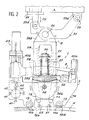
- the pushing force F2 (FIG. 2) is exerted by the aforementioned jack 25 which pushes on the link arm 20 and consequently on the link piece 21 and on the stirrup 22, so that the secondary carriage 7 is pressed into abutment permanent by means of the rolling members 12a and 12b of the guide device 10 on the tubes 5 and 6.
- the combination of forces F1 and F2 means that the flanges of the rollers 13 are in permanent contact with the walls 4a and 4b of the groove 4 (force F1), and that the tires of the rollers 13 are in permanent contact with the tubes 5 and 6 on either side of groove 4 (force F2).
- the support block 9 carries two torches T1 and T2 located between the two probing and rolling assemblies 11a, 12a and 11b, 12b.
- the support block 9 is movable relative to the secondary carriage 7, so as to be able to adjust the penetration depth of the electrodes E1 and E2 inside the groove 4 after each welding pass.
- the support block 9 is slidably mounted along two slides 40a and 40b (FIG. 2) carried by the plate 7a of the secondary carriage 7.
- a jack 43 fixed to the plate 7a of the secondary carriage 7 has its piston rod 44 made integral with the support block 9 to move it along the slides 40a and 40b, in order to bring a pin 45 of the support block 9 into contact with the stop 41 selected at the level of the barrel 42.
- the support block 9 can also be driven by a frequency oscillation movement and amplitude adjustable by mechanical or electrical means, known per se.
- each feeler member 11a or 11b is constituted by a lateral grain carried at the end of a finger 50 which penetrates inside the groove 4.
- This finger like a vertical rod , is slidably mounted in a sleeve 51 which has a threaded lateral opening 52 in which engages a locking means 53 such as a screw, so as to adjust the penetration depth of each grain.
- This adjustment combined with the adjustment of the support block 9 makes it possible to considerably increase the welding precision.
- a feeler 11a or 11b consisting of a grain is better suited than the flange of a roller in the case of a narrow groove.
- the guide device 10 is formed of two probing assemblies 11a, 12a and 11b, 12b with the torches T1 and T2 preferably placed between these two assemblies.
- the probing zones of the flange and of the tire are in line with one another, while the probing zones of the grain and of the ball (or flat roller) can be offset from each other.
- the mechanical guidance system according to the invention is particularly suitable for the butt welding of tube sections of submerged pipes at the bottom of the sea for the exploitation of petroleum deposits.
- the guidance system is essentially used during the first welding passes, that is to say as long as the feelers can penetrate the groove, the end of the welding operation being carried out for example by another conventional welding station.
- the guide system makes it possible to carry out rectilinear horizontal and vertical as well as circular welds.
Landscapes
- Engineering & Computer Science (AREA)
- Physics & Mathematics (AREA)
- Plasma & Fusion (AREA)
- Mechanical Engineering (AREA)
- Arc Welding In General (AREA)
- Butt Welding And Welding Of Specific Article (AREA)
- Paper (AREA)
- Electrotherapy Devices (AREA)
Applications Claiming Priority (2)
| Application Number | Priority Date | Filing Date | Title |
|---|---|---|---|
| FR8917412A FR2656555B1 (fr) | 1989-12-29 | 1989-12-29 | Systeme mecanique de guidage automatique d'une ou plusieurs torches d'une unite de soudage a l'arc. |
| FR8917412 | 1989-12-29 |
Publications (2)
| Publication Number | Publication Date |
|---|---|
| EP0439975A1 true EP0439975A1 (de) | 1991-08-07 |
| EP0439975B1 EP0439975B1 (de) | 1993-06-16 |
Family
ID=9389123
Family Applications (1)
| Application Number | Title | Priority Date | Filing Date |
|---|---|---|---|
| EP90403594A Expired - Lifetime EP0439975B1 (de) | 1989-12-29 | 1990-12-14 | Mechanisches System zur automatischen Führung eines oder mehrerer Brenner eines Lichtbogenschweissgerätes |
Country Status (5)
| Country | Link |
|---|---|
| US (1) | US5146064A (de) |
| EP (1) | EP0439975B1 (de) |
| DK (1) | DK0439975T3 (de) |
| FR (1) | FR2656555B1 (de) |
| NO (1) | NO179964C (de) |
Cited By (6)
| Publication number | Priority date | Publication date | Assignee | Title |
|---|---|---|---|---|
| US6313426B2 (en) | 1998-12-24 | 2001-11-06 | Saipem S.P.A. | Method and apparatus for welding pipes together |
| US6429405B2 (en) | 1998-12-24 | 2002-08-06 | Saipem S.P.A. | Apparatus and method for welding pipes together |
| US6939083B2 (en) | 2001-03-27 | 2005-09-06 | Saipem S.P.A. | Apparatus and method for connecting pipes during underwater pipe-laying |
| US7114881B2 (en) | 2000-10-24 | 2006-10-03 | Saipem S.P.A. | Method and apparatus for welding pipes together |
| US7189028B1 (en) | 1999-07-21 | 2007-03-13 | Saipem, S.P.A. | Underwater pipe-laying |
| WO2010125112A1 (fr) * | 2009-04-29 | 2010-11-04 | SERIMAX Société par Actions Simplifiée | Systeme mecanique de guidage automatique d' une ou plusieurs torches d' une unite de soudage avec trois axes de pivotement pour la (les ) torche ( s ) |
Families Citing this family (19)
| Publication number | Priority date | Publication date | Assignee | Title |
|---|---|---|---|---|
| DE9403709U1 (de) * | 1994-03-04 | 1994-08-04 | Anton Steinecker Entwicklungs Gmbh & Co, 85356 Freising | Vorrichtung zum Schweißen von Profilkörpern auf Flächenkörpern |
| NL1011223C2 (nl) † | 1999-02-05 | 2000-08-10 | Allseas Group Sa | Werkwijze en inrichting voor het aan elkaar lassen van twee pijpen. |
| US6364971B1 (en) * | 2000-01-20 | 2002-04-02 | Electric Power Research Institute | Apparatus and method of repairing turbine blades |
| US6884959B2 (en) | 2001-09-07 | 2005-04-26 | Electric Power Research Institute, Inc. | Controlled composition welding method |
| US8088387B2 (en) * | 2003-10-10 | 2012-01-03 | Immunogen Inc. | Method of targeting specific cell populations using cell-binding agent maytansinoid conjugates linked via a non-cleavable linker, said conjugates, and methods of making said conjugates |
| CN1849769B (zh) * | 2003-09-15 | 2010-06-16 | 英特尔公司 | 利用高吞吐量空间频率分组码的多天线系统和方法 |
| US7371988B2 (en) | 2004-10-22 | 2008-05-13 | Electric Power Research Institute, Inc. | Methods for extending the life of alloy steel welded joints by elimination and reduction of the HAZ |
| US7484651B2 (en) | 2004-10-22 | 2009-02-03 | Electric Power Research Institute, Inc. | Method to join or repair superalloy hot section turbine components using hot isostatic processing |
| KR20200058590A (ko) | 2008-04-30 | 2020-05-27 | 이뮤노젠 아이엔씨 | 가교제 및 그 용도 |
| BRPI1010620B8 (pt) | 2009-06-03 | 2021-05-25 | Immunogen Inc | métodos de conjugação |
| US9475155B2 (en) | 2010-02-02 | 2016-10-25 | Technip Usa, Inc. | Ring gear based welding system |
| US8916791B2 (en) * | 2010-02-02 | 2014-12-23 | Technip Usa, Inc. | Ring gear based welding system |
| US10131682B2 (en) | 2012-11-24 | 2018-11-20 | Hangzhou Dac Biotech Co., Ltd. | Hydrophilic linkers and their uses for conjugation of drugs to a cell binding molecules |
| CA2938919C (en) | 2014-02-28 | 2020-12-29 | Hangzhou Dac Biotech Co., Ltd | Charged linkers and their uses for conjugation |
| FI3319936T3 (fi) | 2015-07-12 | 2026-03-12 | Hangzhou Dac Biotech Co Ltd | Silloituslinkkereitä soluun sitoutuvien molekyylien konjugoimiseksi |
| US9839687B2 (en) | 2015-07-15 | 2017-12-12 | Suzhou M-Conj Biotech Co., Ltd. | Acetylenedicarboxyl linkers and their uses in specific conjugation of a cell-binding molecule |
| CA3042442C (en) | 2016-11-14 | 2024-01-02 | Hangzhou Dac Biotech Co., Ltd | Conjugation linkers, cell binding molecule-drug conjugates containing the linkers, methods of making and uses of such conjugates with the linkers |
| NL2024484B1 (en) * | 2019-12-17 | 2021-09-02 | Sif Netherlands B V | Welding torch assembly |
| EP4104960B1 (de) * | 2021-06-16 | 2025-11-05 | Sif Holding N.V. | Schweissbrenneranordnung |
Citations (3)
| Publication number | Priority date | Publication date | Assignee | Title |
|---|---|---|---|---|
| GB2067310A (en) * | 1979-12-31 | 1981-07-22 | Messer Griesheim Gmbh | Automatic speed control for seam welding |
| WO1985005302A1 (en) * | 1984-05-14 | 1985-12-05 | Evans Pipeline Equipment Company | Welding groove tracking apparatus |
| FR2613265A1 (fr) * | 1987-04-01 | 1988-10-07 | Havre Chantiers | Dispositif mecanique permettant la reconnaissance automatique de profils de type en v notamment de lignes de soudure devant constituer des joints a souder |
Family Cites Families (4)
| Publication number | Priority date | Publication date | Assignee | Title |
|---|---|---|---|---|
| US2441507A (en) * | 1944-12-11 | 1948-05-11 | Lincoln Electric Co | Apparatus for arc welding |
| US2827548A (en) * | 1957-03-06 | 1958-03-18 | Smith Corp A O | Apparatus for welding |
| JPS5440220A (en) * | 1977-09-05 | 1979-03-29 | Fuji Kogyosho Kk | Corrosionn and wearrresistant alloy having resistivity against heat shock and deposition of burnt materials |
| DD243452A1 (de) * | 1985-12-17 | 1987-03-04 | Inst Energieversorgung | Verfahren zur dreidimensionalen schweissfugenabtastung und sensorfuehler zur durchfuehrung des verfahrens |
-
1989
- 1989-12-29 FR FR8917412A patent/FR2656555B1/fr not_active Expired - Fee Related
-
1990
- 1990-12-14 DK DK90403594.6T patent/DK0439975T3/da active
- 1990-12-14 EP EP90403594A patent/EP0439975B1/de not_active Expired - Lifetime
- 1990-12-27 US US07/634,434 patent/US5146064A/en not_active Expired - Fee Related
- 1990-12-28 NO NO905626A patent/NO179964C/no unknown
Patent Citations (3)
| Publication number | Priority date | Publication date | Assignee | Title |
|---|---|---|---|---|
| GB2067310A (en) * | 1979-12-31 | 1981-07-22 | Messer Griesheim Gmbh | Automatic speed control for seam welding |
| WO1985005302A1 (en) * | 1984-05-14 | 1985-12-05 | Evans Pipeline Equipment Company | Welding groove tracking apparatus |
| FR2613265A1 (fr) * | 1987-04-01 | 1988-10-07 | Havre Chantiers | Dispositif mecanique permettant la reconnaissance automatique de profils de type en v notamment de lignes de soudure devant constituer des joints a souder |
Non-Patent Citations (2)
| Title |
|---|
| PATENT ABSTRACTS OF JAPAN vol. 10, no. 122 (M-476), 7 mai 1986; & JP - A - 60250881 (HITACHI KINZOKU K.K.) 11.12.1985 * |
| PATENT ABSTRACTS OF JAPAN vol. 7, no. 50 (M-197), 26 février 1983; & JP - A - 57199570 (NIPPON KOKAN K.K.) 07.12.1982 * |
Cited By (8)
| Publication number | Priority date | Publication date | Assignee | Title |
|---|---|---|---|---|
| US6313426B2 (en) | 1998-12-24 | 2001-11-06 | Saipem S.P.A. | Method and apparatus for welding pipes together |
| US6429405B2 (en) | 1998-12-24 | 2002-08-06 | Saipem S.P.A. | Apparatus and method for welding pipes together |
| US7189028B1 (en) | 1999-07-21 | 2007-03-13 | Saipem, S.P.A. | Underwater pipe-laying |
| US7114881B2 (en) | 2000-10-24 | 2006-10-03 | Saipem S.P.A. | Method and apparatus for welding pipes together |
| US6939083B2 (en) | 2001-03-27 | 2005-09-06 | Saipem S.P.A. | Apparatus and method for connecting pipes during underwater pipe-laying |
| WO2010125112A1 (fr) * | 2009-04-29 | 2010-11-04 | SERIMAX Société par Actions Simplifiée | Systeme mecanique de guidage automatique d' une ou plusieurs torches d' une unite de soudage avec trois axes de pivotement pour la (les ) torche ( s ) |
| FR2944985A1 (fr) * | 2009-04-29 | 2010-11-05 | Hms 634 Ltd | Systeme mecanique de guidage automatique d'une ou plusieurs torches d'une unite de soudage |
| US8987635B2 (en) | 2009-04-29 | 2015-03-24 | Serimax | Automatic mechanical guide system for one or more welding unit torches with three pivot axes for the torch(es) |
Also Published As
| Publication number | Publication date |
|---|---|
| DK0439975T3 (da) | 1993-12-27 |
| EP0439975B1 (de) | 1993-06-16 |
| NO179964B (no) | 1996-10-14 |
| FR2656555B1 (fr) | 1994-10-28 |
| US5146064A (en) | 1992-09-08 |
| FR2656555A1 (fr) | 1991-07-05 |
| NO179964C (no) | 1997-01-22 |
| NO905626L (no) | 1991-07-01 |
| NO905626D0 (no) | 1990-12-28 |
Similar Documents
| Publication | Publication Date | Title |
|---|---|---|
| EP0439975B1 (de) | Mechanisches System zur automatischen Führung eines oder mehrerer Brenner eines Lichtbogenschweissgerätes | |
| EP2424704B1 (de) | Mechanisches system zur automatischen führung von ein oder mehr lötlampen eines schweissgeräts mit drei drehachsen für die lötlampe oder lötlampen | |
| EP0090098B1 (de) | Vorrichtung zum Steuern einer Maschine zum Bau oder zur Instandsetzung eines Eisenbahngleises | |
| CH617617A5 (de) | ||
| WO1997013614A1 (fr) | Dispositif de mesure ou de controle de l'usinage d'une piece cylindrique a mouvement orbital | |
| EP0141717A2 (de) | Positioniereinrichtung für Roboter | |
| EP0611217A1 (de) | Automatische ''in situ'' Schweissmaschine zum Folgen von gekrümmten Konturen, und mit einer Programmiersteuerung zum Extrapolieren | |
| EP0686450A1 (de) | Schneidvorrichtung für profilierte Materialien, insbesonder für Rinnen | |
| WO2021104884A1 (fr) | Système de nettoyage d'une surface vitrée d'un véhicule automobile | |
| EP0545779A1 (de) | Fahrzeug zum automatischen Verlegen von Schienen auf welchen sich das Fahrzeug fortbewegt; und Schiene für diesen Zweck | |
| WO1985002360A1 (fr) | Appareil a pattes adherentes sur une surface non horizontale | |
| EP1809488B1 (de) | Markierungsvorrichtung | |
| FR2559108A1 (fr) | Dispositif de reglage de l'orientation et de l'inclinaison d'un projecteur pour vehicules automobiles | |
| FR2636554A1 (fr) | Dispositif de soudage de toles ou analogues par un faisceau laser | |
| EP0369883B1 (de) | Blankmachvorrichtung der beiden zu verschweissenden Blechkanten | |
| EP0006389B1 (de) | Verfahren und Vorrichtung zur automatischen Schweissnahtabtastung | |
| FR2541603A1 (fr) | Appareil a cintrer | |
| FR2875196A1 (fr) | Essuie-glasse de type pantographique | |
| WO2001003894A1 (fr) | Dispositif de positionnement d'une plaque sur un cylindre a fixation magnetique | |
| CA2298021A1 (fr) | Machine de marquage | |
| FR2926632A1 (fr) | Procede de controle de la conformite dimensionnelle d'une piece et dispositif de mise en oeuvre d'un tel procede | |
| FR2483269A1 (fr) | Ouvreur de bobine | |
| CH677835A5 (en) | Alignment of optical fibres during parameter measurement | |
| FR2575955A1 (fr) | Procede et installation pour la rectification et le controle du diametre d'une meule | |
| FR2554747A1 (fr) | Outil pour le tronconnage de tubes |
Legal Events
| Date | Code | Title | Description |
|---|---|---|---|
| PUAI | Public reference made under article 153(3) epc to a published international application that has entered the european phase |
Free format text: ORIGINAL CODE: 0009012 |
|
| AK | Designated contracting states |
Kind code of ref document: A1 Designated state(s): DK GB NL |
|
| 17P | Request for examination filed |
Effective date: 19910826 |
|
| 17Q | First examination report despatched |
Effective date: 19921105 |
|
| GRAA | (expected) grant |
Free format text: ORIGINAL CODE: 0009210 |
|
| AK | Designated contracting states |
Kind code of ref document: B1 Designated state(s): DK GB NL |
|
| GBT | Gb: translation of ep patent filed (gb section 77(6)(a)/1977) |
Effective date: 19930625 |
|
| REG | Reference to a national code |
Ref country code: DK Ref legal event code: T3 |
|
| PLBE | No opposition filed within time limit |
Free format text: ORIGINAL CODE: 0009261 |
|
| STAA | Information on the status of an ep patent application or granted ep patent |
Free format text: STATUS: NO OPPOSITION FILED WITHIN TIME LIMIT |
|
| 26N | No opposition filed | ||
| PGFP | Annual fee paid to national office [announced via postgrant information from national office to epo] |
Ref country code: GB Payment date: 19961217 Year of fee payment: 7 |
|
| PGFP | Annual fee paid to national office [announced via postgrant information from national office to epo] |
Ref country code: DK Payment date: 19961220 Year of fee payment: 7 |
|
| PGFP | Annual fee paid to national office [announced via postgrant information from national office to epo] |
Ref country code: NL Payment date: 19961231 Year of fee payment: 7 |
|
| PG25 | Lapsed in a contracting state [announced via postgrant information from national office to epo] |
Ref country code: GB Free format text: LAPSE BECAUSE OF NON-PAYMENT OF DUE FEES Effective date: 19971214 Ref country code: DK Free format text: LAPSE BECAUSE OF NON-PAYMENT OF DUE FEES Effective date: 19971214 |
|
| PG25 | Lapsed in a contracting state [announced via postgrant information from national office to epo] |
Ref country code: NL Free format text: LAPSE BECAUSE OF NON-PAYMENT OF DUE FEES Effective date: 19980701 |
|
| GBPC | Gb: european patent ceased through non-payment of renewal fee |
Effective date: 19971214 |
|
| NLV4 | Nl: lapsed or anulled due to non-payment of the annual fee |
Effective date: 19980701 |
|
| REG | Reference to a national code |
Ref country code: DK Ref legal event code: EBP |