EP0440024A2 - Multistage optical fibre amplifier - Google Patents
Multistage optical fibre amplifier Download PDFInfo
- Publication number
- EP0440024A2 EP0440024A2 EP19910100216 EP91100216A EP0440024A2 EP 0440024 A2 EP0440024 A2 EP 0440024A2 EP 19910100216 EP19910100216 EP 19910100216 EP 91100216 A EP91100216 A EP 91100216A EP 0440024 A2 EP0440024 A2 EP 0440024A2
- Authority
- EP
- European Patent Office
- Prior art keywords
- fiber
- amplifier
- signal light
- fiber optic
- input
- Prior art date
- Legal status (The legal status is an assumption and is not a legal conclusion. Google has not performed a legal analysis and makes no representation as to the accuracy of the status listed.)
- Granted
Links
Images

Classifications
-
- H—ELECTRICITY
- H04—ELECTRIC COMMUNICATION TECHNIQUE
- H04B—TRANSMISSION
- H04B10/00—Transmission systems employing electromagnetic waves other than radio-waves, e.g. infrared, visible or ultraviolet light, or employing corpuscular radiation, e.g. quantum communication
- H04B10/29—Repeaters
- H04B10/291—Repeaters in which processing or amplification is carried out without conversion of the main signal from optical form
- H04B10/293—Signal power control
- H04B10/2933—Signal power control considering the whole optical path
- H04B10/2935—Signal power control considering the whole optical path with a cascade of amplifiers
-
- H—ELECTRICITY
- H01—ELECTRIC ELEMENTS
- H01S—DEVICES USING THE PROCESS OF LIGHT AMPLIFICATION BY STIMULATED EMISSION OF RADIATION [LASER] TO AMPLIFY OR GENERATE LIGHT; DEVICES USING STIMULATED EMISSION OF ELECTROMAGNETIC RADIATION IN WAVE RANGES OTHER THAN OPTICAL
- H01S3/00—Lasers, i.e. devices using stimulated emission of electromagnetic radiation in the infrared, visible or ultraviolet wave range
- H01S3/05—Construction or shape of optical resonators; Accommodation of active medium therein; Shape of active medium
- H01S3/06—Construction or shape of active medium
- H01S3/063—Waveguide lasers, i.e. whereby the dimensions of the waveguide are of the order of the light wavelength
- H01S3/067—Fibre lasers
- H01S3/06754—Fibre amplifiers
-
- H—ELECTRICITY
- H04—ELECTRIC COMMUNICATION TECHNIQUE
- H04B—TRANSMISSION
- H04B10/00—Transmission systems employing electromagnetic waves other than radio-waves, e.g. infrared, visible or ultraviolet light, or employing corpuscular radiation, e.g. quantum communication
- H04B10/29—Repeaters
- H04B10/291—Repeaters in which processing or amplification is carried out without conversion of the main signal from optical form
- H04B10/2912—Repeaters in which processing or amplification is carried out without conversion of the main signal from optical form characterised by the medium used for amplification or processing
-
- H—ELECTRICITY
- H01—ELECTRIC ELEMENTS
- H01S—DEVICES USING THE PROCESS OF LIGHT AMPLIFICATION BY STIMULATED EMISSION OF RADIATION [LASER] TO AMPLIFY OR GENERATE LIGHT; DEVICES USING STIMULATED EMISSION OF ELECTROMAGNETIC RADIATION IN WAVE RANGES OTHER THAN OPTICAL
- H01S2301/00—Functional characteristics
- H01S2301/04—Gain spectral shaping, flattening
-
- H—ELECTRICITY
- H01—ELECTRIC ELEMENTS
- H01S—DEVICES USING THE PROCESS OF LIGHT AMPLIFICATION BY STIMULATED EMISSION OF RADIATION [LASER] TO AMPLIFY OR GENERATE LIGHT; DEVICES USING STIMULATED EMISSION OF ELECTROMAGNETIC RADIATION IN WAVE RANGES OTHER THAN OPTICAL
- H01S3/00—Lasers, i.e. devices using stimulated emission of electromagnetic radiation in the infrared, visible or ultraviolet wave range
- H01S3/05—Construction or shape of optical resonators; Accommodation of active medium therein; Shape of active medium
- H01S3/06—Construction or shape of active medium
- H01S3/063—Waveguide lasers, i.e. whereby the dimensions of the waveguide are of the order of the light wavelength
- H01S3/067—Fibre lasers
- H01S3/06754—Fibre amplifiers
- H01S3/06758—Tandem amplifiers
Definitions
- the present invention relates to a fiber optic amplifier according to the preamble of claim 1.
- the object of the present invention is to provide a fiber-optic amplifier of the type mentioned at the outset which offers an amplification which is as constant as possible over a broad wavelength range of a few 10 nm.
- each individual amplifier stage with an individual Equip the amplification function, the wavelength range of the maximum amplification of which is shifted from that of the adjacent stage, so that there is a resulting amplifier function as a function of the wavelength at the signal output of the fiber optic amplifier, the maximum amplification of which is approximately constant over a wide wavelength range in the manner of a bandpass filter characteristic without significant ripple is.
- a fiber optic amplifier is particularly suitable in an advantageous manner for glass fiber transmission systems.
- Another advantage of such a fiber optic amplifier in addition to the large constant gain over a wide bandwidth, is also a large saturation output power and a low noise figure, since both the input stage can be optimized separately for low noise and the output stage can be optimized for high output power.
- the fiber optic amplifier 10 shown in the exemplary embodiment of the present invention by cascading n-amplifier stages 11, 12... 1n while providing pump light sources economically, enables a considerable and, in particular, uniform amplification V of signal light arriving on transmission fiber links, the wavelength of which is preferably in 1536 nm, Band ⁇ S lies.
- the fiber-optic amplifier 10 has a signal light input 21 and a signal light output 22, via which it is arranged, for example, within a transmission fiber link made of, for example, single-mode fibers.
- Each amplifier stage 11, 12 ... 1n of the fiber optic amplifier 10 according to FIG. 1 has a signal light-amplifying fiber piece 31, 32 ... 3n of a certain length L1, L2 ... L n , the base material of which, for example, SiO2 / Ge, SiO2 / Al or the like. And is doped with at least one lanthanoid, for example Er3+ in a certain type and amount.
- Each fiber piece 31, 32 ... 3n is connected at the input-side end in the signal light direction to a first output end 23 of a wavelength-selective directional coupler 41, 42 ... 4n, the second output end 24 of which is terminated without reflection and the second input end 26 of which is connected to a Pump light source 51, 52 ... 5n is connected.
- the first input end 25 of the directional coupler 41 of the first amplifier stage 11 is connected to the signal light input 21 of the fiber optic amplifier 10, while each first input end 25 of the directional coupler 42... 4n is connected to the end of the fiber piece 31, 32... 3n. 1 of the preceding amplifier stage 11, 12, 1n-1 is connected.
- Each pump light source 51, 52 ... 5n emits pump light in the 807 nm range ( ⁇ p1 , ⁇ p2 ... ⁇ pn ) and is realized by an inexpensive printer laser, CD laser or the like. E.g. have such laser pump powers of some 10 mW.
- This gain characteristic has a maximum of relatively small bandwidth at a certain wavelength ⁇ 01, ⁇ 02 ... ⁇ 0n of the signal light.
- the fiber base material can be additionally doped with Er3+ with Yb, P and Al or the like. It is also possible to provide the dopant (s) elsewhere in the fiber cross section.
- the fiber geometry of the individual fiber pieces can be changed in the amplifier stages.
- the different wavelength positions of the gain characteristics V1, V2 ... V n der 3 at the signal output 22 of the fiber optic amplifier 10, a resulting gain characteristic V S , which is the sum of the individual characteristics V1 + V2 + ... + V n results and which has a substantially uniform maximum amplification over a considerable bandwidth of the signal light waveband with considerably less ripple.
- the size of the maximum gain and its ripple depends on the number of amplifier stages 11, 12 ... 1n used. E.g. This results in a broad gain characteristic of low ripple in a wavelength range between 1530 nm and 1560 nm.
Landscapes
- Physics & Mathematics (AREA)
- Electromagnetism (AREA)
- Engineering & Computer Science (AREA)
- Computer Networks & Wireless Communication (AREA)
- Signal Processing (AREA)
- Plasma & Fusion (AREA)
- Optics & Photonics (AREA)
- Lasers (AREA)
- Light Guides In General And Applications Therefor (AREA)
- Optical Fibers, Optical Fiber Cores, And Optical Fiber Bundles (AREA)
Abstract
Ein faseroptischer Verstärker (20), dessen Signallichteingang (21) und -ausgang (22) mit einer Monomodefaser für 1536 nm-Signallicht verbindbar sind, besitzt zwei oder mehr in Kaskade geschaltete Verstärkerstufen (11,12 ... 1n) aus einem Signallicht verstärkenden Faserstück (31,32 ... 3n), das mit mindestens einem Lanthanoid dotiert ist, einem wellenlängenselektiven Richtkoppler (41,42 ... 4n) und einer Pumplichtquelle (51,52 ... 5n). Das in der Durchlaufrichtung des Signallichtes ausgangsseitige Ende des Faserstücks einer Verstärkerstufe ist mit dem einen Eingang des Richtkopplers der folgenden Verstärkerstufe verbunden. Die Faserstücke (31,32 ... 3n) der einzelnen Verstärkerstufen (11,12 ... 1n) sind hinsichtlich Länge und/oder Dotierung und/oder Grundmaterial zum Erreichen einer maximalen Verstärkung bei unterschiedlichen Wellenlängen unterschiedlich zueinander. Ein derartiger faseroptischer Verstärker (10) bietet eine über einen breiten Wellenlängenbereich möglichst konstante Verstärkung.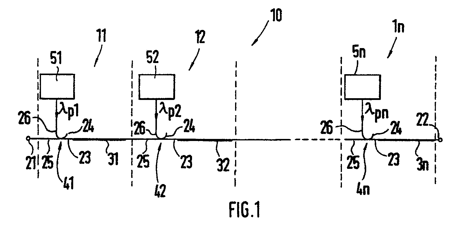
Description
Aus Proc. ECOC 88, Brighton, S. 49 ff. ist es bekannt, daß Lichtleitfasern, die mit einem oder mit mehreren Lanthanoiden, wie bspw. Neodym, Erbium, Ytterbium dotiert sind und als Basis SiO₂ oder Fluoroidglas besitzen, bei Anregung durch Licht bestimmter Wellenlänge als Verstärker unabhängig von der Polarisation der erregenden Lichtwelle wirken. Gemäß Proc. ECOC 88, Brighton, S. 58 ff. wurde eine mit Er³⁺-dotierte SiO₂-Faser über einen Richtkoppler mit Signallicht gespeist und mit Pumplichtquellen unterschiedlicher Pumpleistungen verbunden. Dabei hat sich herausgestellt, daß der Grad der Verstärkung und die Wellenlänge maximaler Verstärkung in den Bereichen zwischen 1520 und 1560 nm von der Pumpleistung der Pumplichtquelle abhängig ist. Als Laserlichtquelle wurde ein 870 nm-Halbleiterlaser verwendet.From proc. ECOC 88, Brighton, p. 49 ff., It is known that optical fibers that are doped with one or more lanthanides, such as neodymium, erbium, ytterbium and have SiO₂ or fluoroid glass as a base, when excited by light of a certain wavelength as Amplifiers act regardless of the polarization of the exciting light wave. According to Proc. ECOC 88, Brighton, p. 58 ff. An Er³⁺-doped SiO₂ fiber was fed with signal light via a directional coupler and connected to pump light sources of different pump powers. It has been found that the degree of amplification and the wavelength of maximum amplification in the ranges between 1520 and 1560 nm depend on the pumping power of the pumping light source. An 870 nm semiconductor laser was used as the laser light source.
Es wurde ferner auch schon darüber berichtet, daß sich die Wellenlänge, bei der eine maximale Verstärkung im Faserstück auftritt, auch in Abhängigkeit von der Dotierung des Faserstücks ändert.It has also been reported that the wavelength at which maximum gain occurs in the fiber piece also depends on the doping of the Fiber piece changes.
Bei bisher versuchsweise verwendeten faseroptischen Verstärkern der eingangs genannten Art erhielt man eine Verstärkung in Abhängigkeit von der Wellenlänge des Signallichtes, wobei der Bereich maximaler Verstärkung relativ schmalbandig ist und beiderseits dieses schmalbandigen Bereichs maximaler Verstärkung expontentiell abnimmt, wie dies aus der oben an zweiter Stelle genannten Literaturstelle hervorgeht. In Glasfaserübertragungssystemen, die mit Intensitätsmodulation und direkter Detektion arbeiten, kann jedoch nur eine möglichst breitbandige Übertragungsfunktion bei möglichst geringer Welligkeit zugelassen werden.In the case of fiber-optic amplifiers of the type mentioned at the outset, which have been used experimentally, an amplification as a function of the wavelength of the signal light was obtained, the range of maximum amplification being relatively narrow-band and on both sides of this narrow-band region of maximum amplification decreasing exponentially, as is described in the literature mentioned above in second place emerges. In fiber optic transmission systems that work with intensity modulation and direct detection, however, only a broadband transmission function with the lowest possible ripple can be permitted.
Aufgabe der vorliegenden Erfindung ist es, einen faseroptischen Verstärker der eingangs genannten Art zu schaffen, der eine über einen breiten Wellenlängenbereich von einigen 10 nm möglichst konstante Verstärkung bietet.The object of the present invention is to provide a fiber-optic amplifier of the type mentioned at the outset which offers an amplification which is as constant as possible over a broad wavelength range of a few 10 nm.
Zur Lösung dieser Aufgabe sind bei einem faseroptischen Verstärker der genannten Art die im Anspruch 1 angegebenen Merkmale vorgesehen.To achieve this object, the features specified in claim 1 are provided in a fiber optic amplifier of the type mentioned.
Durch die erfindungsgemäßen Maßnahmen ist es möglich, jede einzelne Verstärkerstufe mit einer individuellen Verstärkungsfunktion auszustatten, deren Wellenlängenbereich maximaler Verstärkung gegenüber dem der benachbarten Stufe verschoben ist, so daß sich am Signalausgang des faseroptischen Verstärkers eine resultierende Verstärkerfunktion in Abhängigkeit von der Wellenlänge ergibt, deren maximale Verstärkung über einen breiten Wellenlängenbereich nach Art einer Bandfiltercharakteristik ohne wesentliche Welligkeit in etwa konstant ist. Ein derartiger faseroptischer Verstärker ist in vorteilhafter Weise für Glasfaserübertragungssysteme besonders geeignet. Ein weiterer Vorteil eines solchen faseroptischen Verstärkers besteht neben der großen konstanten Verstärkung über eine große Bandbreite außerdem in einer großen Sättigungsausgangsleistung und einer niedrigen Rauschzahl, da sowohl die Eingangsstufe auf geringstes Rauschen als auch die Ausgangsstufe auf große Ausgangsleistung separat optimiert werden können.The measures according to the invention make it possible to provide each individual amplifier stage with an individual Equip the amplification function, the wavelength range of the maximum amplification of which is shifted from that of the adjacent stage, so that there is a resulting amplifier function as a function of the wavelength at the signal output of the fiber optic amplifier, the maximum amplification of which is approximately constant over a wide wavelength range in the manner of a bandpass filter characteristic without significant ripple is. Such a fiber optic amplifier is particularly suitable in an advantageous manner for glass fiber transmission systems. Another advantage of such a fiber optic amplifier, in addition to the large constant gain over a wide bandwidth, is also a large saturation output power and a low noise figure, since both the input stage can be optimized separately for low noise and the output stage can be optimized for high output power.
Zweckmäßigerweise können dabei die Merkmale gemäß Anspruch 2 und/oder Anspruch 3 vorgesehen sein. Die Bereitstellung unterschiedlicher Faserstücke kann in einfacher Weise dadurch erfolgen, daß unterschiedliche Faserarten in großer Länge hergestellt werden und zur Bildung eines derartigen faseroptischen Verstärkers jeweils auf entsprechende Länge geschnitten und in die einzelnen Verstärkerstufen in unterschiedlicher Weise eingesetzt werden.The features according to claim 2 and / or claim 3 can expediently be provided. Different fiber pieces can be provided in a simple manner by producing different types of fiber over great lengths and, in order to form such a fiber optic amplifier, in each case cut to the appropriate length and into the individual amplifier stages can be used in different ways.
Weitere vorteilhafte Ausgestaltungen ergeben sich aus der Kombination mit einzelnen oder mehreren der Unteransprüche 4 bis 7. Insbesondere das Vorsehen der Merkmale gemäß Anspruch 6 und/oder 7 ergibt eine äußerst wirtschaftliche Bereitstellung von Pumplicht.Further advantageous configurations result from the combination with one or more of subclaims 4 to 7. In particular, the provision of the features according to claim 6 and / or 7 results in an extremely economical provision of pump light.
Weitere Einzelheiten der Erfindung sind der folgenden Beschreibung zu entnehmen, in der die Erfindung anhand des in der Zeichnung dargestellten Ausführungsbeispieles näher beschrieben und erläutert ist. Es zeigen:
- Figur 1
- in schematischer Darstellung einen n-stufigen faseroptischen Verstärker gemäß einem bevorzugten Ausführungsbeispiel vorliegender Erfindung und
- Figur 2
- Beispiele von Verstärkerkennlinien einzelner Verstärkerstufen und eine daraus resultierende Kennlinie eines aus drei Verstärkerstufen bestehenden faseroptischen Verstärkers gemäß dem Ausführungsbeispiel der Fig. 1.
- Figure 1
- a schematic representation of an n-stage fiber optic amplifier according to a preferred embodiment of the present invention and
- Figure 2
- Examples of amplifier characteristic curves of individual amplifier stages and a characteristic curve resulting therefrom of a fiber-optic amplifier consisting of three amplifier stages according to the exemplary embodiment in FIG. 1.
Der in der Zeichnung gemäß einem bevorzugten Ausführungsbeispiel vorliegender Erfindung dargestellte faseroptische Verstärker 10 ermöglicht durch Kaskadierung von n-Verstärkerstufen 11, 12...1n unter wirtschaftlicher Bereitstellung von Pumplichtquellen eine erhebliche und insbesondere über ein breites Frequenzband gleichmäßige Verstärkung V von auf Übertragungsfaserstrecken ankommendem Signallicht, dessen Wellenlänge vorzugsweise in 1536 nm-Band λ S liegt.The one in the drawing according to a preferred one The fiber
Der faseroptische Verstärker 10 besitzt einen Signallichteingang 21 und einen Signallichtausgang 22, über die er bspw. innerhalb einer Übertragungsfaserstrecke aus bspw. Monomodefasern angeordnet ist. Jede Verstärkerstufe 11, 12 ... 1n des faseroptischen Verstärkers 10 besitzt gemäß Fig. 1 ein Signallicht verstärkendes Faserstück 31, 32 ... 3n bestimmter Länge L₁ , L₂ ... Ln, dessen Grundmaterial bspw. SiO₂/Ge, SiO₂/Al oder dgl. ist und mit mindestens einem Lanthanoid, bspw. Er³⁺ in bestimmter Art und Menge dotiert ist.The fiber-
Jedes Faserstück 31, 32 ... 3n ist am in Signallichtrichtung eingangsseitigen Ende mit einem ersten Ausgangsende 23 eines wellenlängenselektiven Richtkopplers 41, 42 ... 4n verbunden, dessen zweites Ausgangsende 24 reflektionsfrei abgeschlossen ist und dessen zweites Eingangsende 26 mit einer Pumplichtquelle 51, 52 ... 5n verbunden ist.Each
Das erste Eingangsende 25 des Richtkopplers 41 der ersten Verstärkerstufe 11 ist mit dem Signallichteingang 21 des faseroptischen Verstärkers 10 verbunden, während jedes erste Eingangsende 25 der Richtkoppler 42 ... 4n mit dem in Signallichtrichtung ausgangsseitigen Ende des Faserstücks 31, 32 ... 3n-1 der vorhergehenden Verstärkerstufe 11, 12, 1n-1 verbunden ist.The
Jede Pumplichtquelle 51, 52 ... 5n emittiert Pumplicht im 807 nm-Bereich (λp1,λp2 ...λpn) und ist durch einen kostengünstigen Druckerlaser, CD-Laser oder dgl. verwirklicht. Bspw. besitzen derartige Laser Pumpleistungen von einigen 10 mW.Each
Jedes Faserstück 31, 32 .... 3n, dessen Lanthanoid-Ionen vom Pumplicht (Zp) angeregt werden, in ein höheres Energieniveau zu steigen, welche Energie dann durch das Signallicht(λ S) freigesetzt wird, besitzt eine Verstärkungskennlinie V₁,V₂ ... Vn in Abhängigkeit von der Wellenlänge des Signallichtbandes, wie sie in Fig. 2 bei 61, 62, 63 dargestellt ist. Diese Verstärkungskennlinie besitzt bei einer bestimmten Wellenlänge λ₀₁,λ₀₂ ... λ0n des Signallichtes ein Maximum relativ geringer Bandbreite.Each piece of
Werden Pumplichtquellen 51, 52 ... 5n im wesentlichen gleicher Pumpleistung verwendet, so ergeben sich größenordnungsmäßig im wesentlichen dieselben Kennlinien, d.h. die Kennlinie V₁ ,V₂ und V₃ (bei drei Verstärkerstufen 11, 12, 13) besitzen größenordnungsmäßig dieselbe maximale Verstärkung bei jeweils gleicher Bandbreite. Die Verschiebung der Kennlinien V₁ ,V₂,V₃ in Abhängigkeit von der Wellenlänge des übertragenen Signallichtbandes, d.h. die Verschiebung des Wellenlängenbereiches mit maximaler Verstärkung wird durch verschiedenartige Ausgestaltung der Faserstücke 31, 32, ... 3n in den einzelnen Verstärkerstufen 11, 12 ... 1n erreicht. Bspw. werden unterschiedliche Längen L₁ ,L₂ ... Ln (z.B. im Bereich von 1 bis 5m) für die einzelnen Faserstücke 31, 32 .... 3n vorgesehen. Stattdessen oder zusätzlich hierzu ist es möglich, die Art und Menge der Dotierung des Grundmaterials der Faser der einzelnen Faserstücke 31, 32 ... 3n zu ändern. Bspw. kann das Fasergrundmaterial außer mit Er³⁺ mit Yb, P und Al oder dgl. zusätzlich dotiert sein. Es ist außerdem möglich, das oder die Dotierstoffe an anderer Stelle des Faserquerschnitts vorzusehen. Außerdem oder zusätzlich kann noch die Fasergeometrie der einzelnen Faserstücke in den Verstärkerstufen verändert sein.If
Jedenfalls ergibt sich durch die unterschiedliche Wellenlängenlagen der Verstärkungskennlinien V₁,V₂ ... Vn der einzelnen Verstärkerstufen gemäß Fig. 3 am Signalausgang 22 des faseroptischen Verstärkers 10 eine resultierende Verstärkungskennlinie VS, die sich aus der Summe der Einzelkennlinien V₁+V₂+ .. . +Vn ergibt und die bei erheblich geringerer Welligkeit eine im wesentlichen gleichmäßige maximale Verstärkung über eine erhebliche Bandbreite des Signallichtwellenbandes besitzt.In any case, the different wavelength positions of the gain characteristics V₁, V₂ ... V n der 3 at the
Es versteht sich, daß die Größe der maximalen Verstärkung und deren Welligkeit von der Anzahl der verwendeten Verstärkerstufen 11, 12 ... 1n abhängig ist. Bspw. ergibt sich dadurch eine breite Verstärkungscharakteristik geringer Welligkeit in einem Wellenlängenbereich zwischen 1530 nm und 1560 nm.It is understood that the size of the maximum gain and its ripple depends on the number of
Claims (7)
Applications Claiming Priority (2)
| Application Number | Priority Date | Filing Date | Title |
|---|---|---|---|
| DE4002369A DE4002369A1 (en) | 1990-01-27 | 1990-01-27 | Multistage fibre=optic amplifier - provides constant amplification over large range of wavelengths using selective directional coupler and pump light source |
| DE4002369 | 1990-01-27 |
Publications (3)
| Publication Number | Publication Date |
|---|---|
| EP0440024A2 true EP0440024A2 (en) | 1991-08-07 |
| EP0440024A3 EP0440024A3 (en) | 1992-06-03 |
| EP0440024B1 EP0440024B1 (en) | 1994-07-20 |
Family
ID=6398880
Family Applications (1)
| Application Number | Title | Priority Date | Filing Date |
|---|---|---|---|
| EP91100216A Expired - Lifetime EP0440024B1 (en) | 1990-01-27 | 1991-01-09 | Multistage optical fibre amplifier |
Country Status (6)
| Country | Link |
|---|---|
| US (1) | US5111334A (en) |
| EP (1) | EP0440024B1 (en) |
| JP (1) | JP2957719B2 (en) |
| AU (1) | AU640726B2 (en) |
| DE (2) | DE4002369A1 (en) |
| ES (1) | ES2061079T3 (en) |
Cited By (3)
| Publication number | Priority date | Publication date | Assignee | Title |
|---|---|---|---|---|
| EP0654872A1 (en) * | 1993-11-24 | 1995-05-24 | Sumitomo Electric Industries, Ltd | Optical fiber amplifier and optical amplifier repeater |
| GB2294170A (en) * | 1994-09-26 | 1996-04-17 | Fujitsu Ltd | Optical amplification of wavelength-division-multiplexed signals |
| US5721635A (en) * | 1993-11-24 | 1998-02-24 | Sumitomo Electric Industries, Ltd. | Optical fiber amplifier and optical amplifier repeater |
Families Citing this family (34)
| Publication number | Priority date | Publication date | Assignee | Title |
|---|---|---|---|---|
| FR2682547A1 (en) * | 1991-10-15 | 1993-04-16 | Alcatel Nv | AMPLIFIER OPTICAL FIBER LINK. |
| US5185826A (en) * | 1992-02-07 | 1993-02-09 | At&T Bell Laboratories | Hybrid pumping arrangement for doped fiber amplifiers |
| US5325380A (en) * | 1992-07-17 | 1994-06-28 | Trw Inc. | Dual wavelength laser emitter |
| JPH06302921A (en) * | 1993-04-13 | 1994-10-28 | Furukawa Electric Co Ltd:The | Optical amplifier |
| GB9318688D0 (en) * | 1993-09-09 | 1993-10-27 | Northern Telecom Ltd | Optical amplifiers |
| JP2742513B2 (en) * | 1993-11-18 | 1998-04-22 | 松下電器産業株式会社 | Optical fiber amplifier and optical fiber transmission system using it |
| US5530583A (en) * | 1993-11-18 | 1996-06-25 | Matsushita Electric Industrial Co., Ltd. | Optical signal amplification apparatus and an optical fiber transmission system using the same |
| FR2715481B1 (en) * | 1994-01-26 | 1996-02-16 | Mathilde Semenkoff | Optical fiber optic amplifier in doped fluorinated glass and method of manufacturing this amplifier. |
| US5392154A (en) * | 1994-03-30 | 1995-02-21 | Bell Communications Research, Inc. | Self-regulating multiwavelength optical amplifier module for scalable lightwave communications systems |
| IT1273676B (en) * | 1994-07-25 | 1997-07-09 | Pirelli Cavi Spa | MULTIPLATION AMPLIFIED TELECOMMUNICATION SYSTEM WITH WAVELENGTH DIVISION, WITH EQUALIZED RECEPTION POWER |
| PE41196A1 (en) * | 1994-07-25 | 1996-12-17 | Pirelli Cavi Spa | AMPLIFIED TELECOMMUNICATION SYSTEM FOR MULTIPLEX TRANSMISSIONS BY WAVE LENGTH DIVISION, ABLE TO LIMIT THE VARIATIONS IN THE OUTPUT POWER |
| US6011644A (en) | 1994-07-29 | 2000-01-04 | Corning Incorporated | Hybrid fiber amplifier |
| US5530709A (en) * | 1994-09-06 | 1996-06-25 | Sdl, Inc. | Double-clad upconversion fiber laser |
| DE69637562D1 (en) * | 1995-03-20 | 2008-07-24 | Fujitsu Ltd | Method and device for optical signal processing |
| IT1275554B (en) * | 1995-07-14 | 1997-08-07 | Pirelli Cavi Spa | OPTICAL NOISE REDUCTION DEVICE DUE TO FOUR WAVE INTERACTION |
| JP4036489B2 (en) * | 1995-08-23 | 2008-01-23 | 富士通株式会社 | Method and apparatus for controlling an optical amplifier for optically amplifying wavelength multiplexed signals |
| SE517698C2 (en) * | 1995-08-25 | 2002-07-02 | Saab Ab | Device for cascading optical amplifiers intended to amplify optical pulses |
| JP2776322B2 (en) * | 1995-09-14 | 1998-07-16 | 日本電気株式会社 | Optical amplifier |
| JP3556026B2 (en) * | 1995-10-30 | 2004-08-18 | 富士通株式会社 | Multi-wavelength optical amplifier that amplifies multiple wavelength signals at once |
| KR970064034A (en) * | 1996-02-10 | 1997-09-12 | 김광호 | Optical transmission systems and lasers for multi-wavelength automatic power and gain control |
| JP3670434B2 (en) * | 1996-04-22 | 2005-07-13 | ルーセント テクノロジーズ インコーポレーテッド | System with multistage optical fiber amplifier |
| US5764406A (en) * | 1996-10-01 | 1998-06-09 | Corning Incorporated | Hydrid optical amplifier having improved dynamic gain tilt |
| KR100258970B1 (en) * | 1997-11-20 | 2000-06-15 | 윤종용 | Optical fiber amplifier |
| EP2306605B1 (en) * | 1998-07-23 | 2012-05-23 | The Furukawa Electric Co., Ltd. | Pumping unit for a Raman amplifier and Raman amplifier comprising the same |
| FR2784826A1 (en) * | 1998-10-15 | 2000-04-21 | Cit Alcatel | REPEATER FOR WAVELENGTH MULTIPLEXED LONG-RANGE FIBER OPTIC TRANSMISSION SYSTEM |
| US6587241B1 (en) | 1999-08-20 | 2003-07-01 | Corvis Corporation | Optical protection methods, systems, and apparatuses |
| RU2152692C1 (en) * | 1999-09-21 | 2000-07-10 | Бобрышев Владимир Дмитриевич | Converter of thermal image column into electric signal |
| US6307668B1 (en) | 1999-10-04 | 2001-10-23 | Optigain, Inc. | Ultra-wide bandwidth fiber based optical amplifier |
| CA2394620A1 (en) | 1999-12-16 | 2001-06-21 | Douglas E. Goforth | Optical gain fibers |
| US6353497B1 (en) | 2000-03-03 | 2002-03-05 | Optical Coating Laboratory, Inc. | Integrated modular optical amplifier |
| US6384962B1 (en) | 2000-06-07 | 2002-05-07 | Tycom (Us) Inc. | Method and apparatus to perform automatic gain equalization using raman amplifiers |
| US6456425B1 (en) | 2000-06-07 | 2002-09-24 | Tyco Telecommunications (Us) Inc. | Method and apparatus to perform lumped raman amplification |
| ATE313878T1 (en) | 2000-07-10 | 2006-01-15 | Mpb Technologies Inc | CASCADED PUMPING SYSTEM FOR DISTRIBUTED RAMAN AMPLIFICATION IN FIBER OPTICAL TRANSMISSION SYSTEMS |
| US20060274404A1 (en) * | 2005-06-06 | 2006-12-07 | Francois Brunet | Optical fiber amplifier system and method |
Family Cites Families (11)
| Publication number | Priority date | Publication date | Assignee | Title |
|---|---|---|---|---|
| US3731226A (en) * | 1971-11-10 | 1973-05-01 | American Optical Corp | Laser using phosphate base laser glass |
| US4173738A (en) * | 1977-02-18 | 1979-11-06 | Owens-Illinois, Inc. | Solid state laser amplifier having two output wavelengths |
| US4528671A (en) * | 1981-11-02 | 1985-07-09 | General Electric Company | Multiple host face-pumped laser |
| US4723824A (en) * | 1983-11-25 | 1988-02-09 | The Board Of Trustees Of The Leland Stanford Junior University | Fiber optic amplifier |
| US4938556A (en) * | 1983-11-25 | 1990-07-03 | The Board Of Trustees Of The Leland Stanford Junior University | Superfluorescent broadband fiber laser source |
| US4794346A (en) * | 1984-11-21 | 1988-12-27 | Bell Communications Research, Inc. | Broadband semiconductor optical amplifier structure |
| US4680769A (en) * | 1984-11-21 | 1987-07-14 | Bell Communications Research, Inc. | Broadband laser amplifier structure |
| USH882H (en) * | 1989-06-01 | 1991-01-01 | Multiple-section pulsed gas laser | |
| US4963832A (en) * | 1989-08-08 | 1990-10-16 | At&T Bell Laboratories | Erbium-doped fiber amplifier coupling device |
| US5005175A (en) * | 1989-11-27 | 1991-04-02 | At&T Bell Laboratories | Erbium-doped fiber amplifier |
| US5050949A (en) * | 1990-06-22 | 1991-09-24 | At&T Bell Laboratories | Multi-stage optical fiber amplifier |
-
1990
- 1990-01-27 DE DE4002369A patent/DE4002369A1/en not_active Withdrawn
- 1990-12-27 AU AU68421/90A patent/AU640726B2/en not_active Ceased
-
1991
- 1991-01-09 US US07/638,509 patent/US5111334A/en not_active Expired - Lifetime
- 1991-01-09 EP EP91100216A patent/EP0440024B1/en not_active Expired - Lifetime
- 1991-01-09 DE DE59102205T patent/DE59102205D1/en not_active Expired - Lifetime
- 1991-01-09 ES ES91100216T patent/ES2061079T3/en not_active Expired - Lifetime
- 1991-01-28 JP JP3026865A patent/JP2957719B2/en not_active Expired - Lifetime
Cited By (7)
| Publication number | Priority date | Publication date | Assignee | Title |
|---|---|---|---|---|
| EP0654872A1 (en) * | 1993-11-24 | 1995-05-24 | Sumitomo Electric Industries, Ltd | Optical fiber amplifier and optical amplifier repeater |
| US5532870A (en) * | 1993-11-24 | 1996-07-02 | Sumitomo Electric Industries, Ltd. | Optical fiber amplifier and optical amplifier repeater |
| US5640269A (en) * | 1993-11-24 | 1997-06-17 | Sumitomo Electric Industries, Inc. | Optical fiber amplifier and optical amplifier repeater |
| US5721635A (en) * | 1993-11-24 | 1998-02-24 | Sumitomo Electric Industries, Ltd. | Optical fiber amplifier and optical amplifier repeater |
| GB2294170A (en) * | 1994-09-26 | 1996-04-17 | Fujitsu Ltd | Optical amplification of wavelength-division-multiplexed signals |
| GB2294170B (en) * | 1994-09-26 | 1997-05-14 | Fujitsu Ltd | Optical amplification of wavelength-division-multiplexed signals |
| US5764404A (en) * | 1994-09-26 | 1998-06-09 | Fujitsu Limited | Wavelength-division-multiplexing optical amplifier |
Also Published As
| Publication number | Publication date |
|---|---|
| DE4002369A1 (en) | 1991-08-01 |
| JP2957719B2 (en) | 1999-10-06 |
| AU640726B2 (en) | 1993-09-02 |
| AU6842190A (en) | 1991-08-01 |
| JPH04212490A (en) | 1992-08-04 |
| EP0440024B1 (en) | 1994-07-20 |
| EP0440024A3 (en) | 1992-06-03 |
| ES2061079T3 (en) | 1994-12-01 |
| DE59102205D1 (en) | 1994-08-25 |
| US5111334A (en) | 1992-05-05 |
Similar Documents
| Publication | Publication Date | Title |
|---|---|---|
| EP0440024B1 (en) | Multistage optical fibre amplifier | |
| DE19947111C2 (en) | Parallel optical fiber amplifier with high power conversion efficiency and wide wavelength band | |
| DE69430614T2 (en) | Fiber optic amplifier and optical repeater | |
| DE69900360T2 (en) | Device with cascaded Raman fiber resonator | |
| DE69325672T2 (en) | Optical amplifier | |
| DE69506077T2 (en) | Optical amplifier | |
| DE69700194T2 (en) | Fiber optic Raman amplifier pumped in the opposite direction and its use in fiber optic communication systems | |
| DE69313157T2 (en) | Optical filter and optical amplifier with this filter | |
| DE19549868B4 (en) | Optical pulse amplification using chirped Bragg gratings | |
| DE69729832T2 (en) | Device with fiber optic laser pumped by the sheath | |
| DE69107872T2 (en) | Optical amplifier with a curved active single-mode fiber. | |
| DE69835466T2 (en) | Optical amplifier | |
| DE69318618T2 (en) | Optical amplifier with automatic self-adjusting gain spectrum | |
| DE69815314T2 (en) | MULTI-STAGE FIBER OPTICAL AMPLIFIER | |
| DE69303112T2 (en) | Optical power limiting amplifier | |
| DE69321532T2 (en) | Fiber optic amplifiers and lasers with an even profit spectrum | |
| DE69616247T2 (en) | Optical fiber amplifier and associated operating method | |
| DE69116691T2 (en) | ERBIUM-Doped FIBER AMPLIFIER WITH MODIFIED SPECTRAL REINFORCEMENT | |
| DE69900002T2 (en) | Method and device with cascaded Raman resonator | |
| DE69531178T2 (en) | Optical waveguide amplifier | |
| DE60131494T2 (en) | Waveguide laser and optical amplifier with increased thermal stability | |
| DE69113714T2 (en) | Light amplifier with optical fiber. | |
| DE60125332T2 (en) | Broadband erbium doped fiber amplifier | |
| DE69026815T2 (en) | OPTICAL AMPLIFIER | |
| DE60019658T2 (en) | Multi-wavelength optical multiplexing device, multi-wavelength light source with such a device and optical amplifier |
Legal Events
| Date | Code | Title | Description |
|---|---|---|---|
| PUAI | Public reference made under article 153(3) epc to a published international application that has entered the european phase |
Free format text: ORIGINAL CODE: 0009012 |
|
| AK | Designated contracting states |
Kind code of ref document: A2 Designated state(s): AT BE CH DE DK ES FR GB IT LI NL SE |
|
| PUAL | Search report despatched |
Free format text: ORIGINAL CODE: 0009013 |
|
| AK | Designated contracting states |
Kind code of ref document: A3 Designated state(s): AT BE CH DE DK ES FR GB IT LI NL SE |
|
| 17P | Request for examination filed |
Effective date: 19920613 |
|
| RAP3 | Party data changed (applicant data changed or rights of an application transferred) |
Owner name: ALCATEL SEL AKTIENGESELLSCHAFT |
|
| 17Q | First examination report despatched |
Effective date: 19931126 |
|
| RBV | Designated contracting states (corrected) |
Designated state(s): CH DE ES FR GB IT LI SE |
|
| GRAA | (expected) grant |
Free format text: ORIGINAL CODE: 0009210 |
|
| AK | Designated contracting states |
Kind code of ref document: B1 Designated state(s): CH DE ES FR GB IT LI SE |
|
| ITF | It: translation for a ep patent filed | ||
| GBT | Gb: translation of ep patent filed (gb section 77(6)(a)/1977) |
Effective date: 19940725 |
|
| REF | Corresponds to: |
Ref document number: 59102205 Country of ref document: DE Date of ref document: 19940825 |
|
| ET | Fr: translation filed | ||
| REG | Reference to a national code |
Ref country code: ES Ref legal event code: FG2A Ref document number: 2061079 Country of ref document: ES Kind code of ref document: T3 |
|
| EAL | Se: european patent in force in sweden |
Ref document number: 91100216.0 |
|
| PLBE | No opposition filed within time limit |
Free format text: ORIGINAL CODE: 0009261 |
|
| STAA | Information on the status of an ep patent application or granted ep patent |
Free format text: STATUS: NO OPPOSITION FILED WITHIN TIME LIMIT |
|
| 26N | No opposition filed | ||
| PGFP | Annual fee paid to national office [announced via postgrant information from national office to epo] |
Ref country code: CH Payment date: 20001214 Year of fee payment: 11 |
|
| REG | Reference to a national code |
Ref country code: GB Ref legal event code: IF02 |
|
| PG25 | Lapsed in a contracting state [announced via postgrant information from national office to epo] |
Ref country code: LI Free format text: LAPSE BECAUSE OF NON-PAYMENT OF DUE FEES Effective date: 20020131 Ref country code: CH Free format text: LAPSE BECAUSE OF NON-PAYMENT OF DUE FEES Effective date: 20020131 |
|
| REG | Reference to a national code |
Ref country code: CH Ref legal event code: PL |
|
| PGFP | Annual fee paid to national office [announced via postgrant information from national office to epo] |
Ref country code: SE Payment date: 20091223 Year of fee payment: 20 |
|
| PGFP | Annual fee paid to national office [announced via postgrant information from national office to epo] |
Ref country code: ES Payment date: 20100125 Year of fee payment: 20 |
|
| PGFP | Annual fee paid to national office [announced via postgrant information from national office to epo] |
Ref country code: FR Payment date: 20100223 Year of fee payment: 20 Ref country code: IT Payment date: 20100127 Year of fee payment: 20 |
|
| PGFP | Annual fee paid to national office [announced via postgrant information from national office to epo] |
Ref country code: DE Payment date: 20100121 Year of fee payment: 20 Ref country code: GB Payment date: 20100121 Year of fee payment: 20 |
|
| REG | Reference to a national code |
Ref country code: GB Ref legal event code: PE20 Expiry date: 20110108 |
|
| REG | Reference to a national code |
Ref country code: ES Ref legal event code: FD2A Effective date: 20110615 |
|
| PG25 | Lapsed in a contracting state [announced via postgrant information from national office to epo] |
Ref country code: GB Free format text: LAPSE BECAUSE OF EXPIRATION OF PROTECTION Effective date: 20110108 Ref country code: ES Free format text: LAPSE BECAUSE OF EXPIRATION OF PROTECTION Effective date: 20110110 |
|
| PG25 | Lapsed in a contracting state [announced via postgrant information from national office to epo] |
Ref country code: DE Free format text: LAPSE BECAUSE OF EXPIRATION OF PROTECTION Effective date: 20110109 |