EP0440124B1 - Bar code label and bar code reader - Google Patents
Bar code label and bar code reader Download PDFInfo
- Publication number
- EP0440124B1 EP0440124B1 EP91101047A EP91101047A EP0440124B1 EP 0440124 B1 EP0440124 B1 EP 0440124B1 EP 91101047 A EP91101047 A EP 91101047A EP 91101047 A EP91101047 A EP 91101047A EP 0440124 B1 EP0440124 B1 EP 0440124B1
- Authority
- EP
- European Patent Office
- Prior art keywords
- bar code
- magnetic
- code reader
- code label
- circuit
- Prior art date
- Legal status (The legal status is an assumption and is not a legal conclusion. Google has not performed a legal analysis and makes no representation as to the accuracy of the status listed.)
- Expired - Lifetime
Links
Images




Classifications
-
- G—PHYSICS
- G06—COMPUTING OR CALCULATING; COUNTING
- G06K—GRAPHICAL DATA READING; PRESENTATION OF DATA; RECORD CARRIERS; HANDLING RECORD CARRIERS
- G06K1/00—Methods or arrangements for marking the record carrier in digital fashion
- G06K1/12—Methods or arrangements for marking the record carrier in digital fashion otherwise than by punching
- G06K1/125—Methods or arrangements for marking the record carrier in digital fashion otherwise than by punching by magnetic means
-
- G—PHYSICS
- G06—COMPUTING OR CALCULATING; COUNTING
- G06K—GRAPHICAL DATA READING; PRESENTATION OF DATA; RECORD CARRIERS; HANDLING RECORD CARRIERS
- G06K19/00—Record carriers for use with machines and with at least a part designed to carry digital markings
- G06K19/02—Record carriers for use with machines and with at least a part designed to carry digital markings characterised by the selection of materials, e.g. to avoid wear during transport through the machine
-
- G—PHYSICS
- G06—COMPUTING OR CALCULATING; COUNTING
- G06K—GRAPHICAL DATA READING; PRESENTATION OF DATA; RECORD CARRIERS; HANDLING RECORD CARRIERS
- G06K19/00—Record carriers for use with machines and with at least a part designed to carry digital markings
- G06K19/06—Record carriers for use with machines and with at least a part designed to carry digital markings characterised by the kind of the digital marking, e.g. shape, nature, code
- G06K19/06187—Record carriers for use with machines and with at least a part designed to carry digital markings characterised by the kind of the digital marking, e.g. shape, nature, code with magnetically detectable marking
-
- G—PHYSICS
- G06—COMPUTING OR CALCULATING; COUNTING
- G06K—GRAPHICAL DATA READING; PRESENTATION OF DATA; RECORD CARRIERS; HANDLING RECORD CARRIERS
- G06K19/00—Record carriers for use with machines and with at least a part designed to carry digital markings
- G06K19/06—Record carriers for use with machines and with at least a part designed to carry digital markings characterised by the kind of the digital marking, e.g. shape, nature, code
- G06K19/06187—Record carriers for use with machines and with at least a part designed to carry digital markings characterised by the kind of the digital marking, e.g. shape, nature, code with magnetically detectable marking
- G06K19/06196—Constructional details
-
- G—PHYSICS
- G06—COMPUTING OR CALCULATING; COUNTING
- G06K—GRAPHICAL DATA READING; PRESENTATION OF DATA; RECORD CARRIERS; HANDLING RECORD CARRIERS
- G06K19/00—Record carriers for use with machines and with at least a part designed to carry digital markings
- G06K19/06—Record carriers for use with machines and with at least a part designed to carry digital markings characterised by the kind of the digital marking, e.g. shape, nature, code
- G06K19/08—Record carriers for use with machines and with at least a part designed to carry digital markings characterised by the kind of the digital marking, e.g. shape, nature, code using markings of different kinds or more than one marking of the same kind in the same record carrier, e.g. one marking being sensed by optical and the other by magnetic means
- G06K19/10—Record carriers for use with machines and with at least a part designed to carry digital markings characterised by the kind of the digital marking, e.g. shape, nature, code using markings of different kinds or more than one marking of the same kind in the same record carrier, e.g. one marking being sensed by optical and the other by magnetic means at least one kind of marking being used for authentication, e.g. of credit or identity cards
- G06K19/14—Record carriers for use with machines and with at least a part designed to carry digital markings characterised by the kind of the digital marking, e.g. shape, nature, code using markings of different kinds or more than one marking of the same kind in the same record carrier, e.g. one marking being sensed by optical and the other by magnetic means at least one kind of marking being used for authentication, e.g. of credit or identity cards the marking being sensed by radiation
-
- G—PHYSICS
- G06—COMPUTING OR CALCULATING; COUNTING
- G06K—GRAPHICAL DATA READING; PRESENTATION OF DATA; RECORD CARRIERS; HANDLING RECORD CARRIERS
- G06K7/00—Methods or arrangements for sensing record carriers, e.g. for reading patterns
- G06K7/08—Methods or arrangements for sensing record carriers, e.g. for reading patterns by means detecting the change of an electrostatic or magnetic field, e.g. by detecting change of capacitance between electrodes
- G06K7/082—Methods or arrangements for sensing record carriers, e.g. for reading patterns by means detecting the change of an electrostatic or magnetic field, e.g. by detecting change of capacitance between electrodes using inductive or magnetic sensors
- G06K7/087—Methods or arrangements for sensing record carriers, e.g. for reading patterns by means detecting the change of an electrostatic or magnetic field, e.g. by detecting change of capacitance between electrodes using inductive or magnetic sensors flux-sensitive, e.g. magnetic, detectors
-
- G—PHYSICS
- G06—COMPUTING OR CALCULATING; COUNTING
- G06K—GRAPHICAL DATA READING; PRESENTATION OF DATA; RECORD CARRIERS; HANDLING RECORD CARRIERS
- G06K19/00—Record carriers for use with machines and with at least a part designed to carry digital markings
- G06K19/06—Record carriers for use with machines and with at least a part designed to carry digital markings characterised by the kind of the digital marking, e.g. shape, nature, code
- G06K2019/06215—Aspects not covered by other subgroups
- G06K2019/06271—Relief-type marking
Definitions
- the present invention relates to a bar code label in which information on each of various commodities, outdoor installations or individuals are recorded as engraved in the form of characters and bar codes.
- the bar code label is well known and widely used as attached on the surface of a box or package in which a commodity or delivery is packed.
- the bar code label carries a variety of information, as coded in the form of bars different in width from one another, on such commodity. The information are used for a higher efficiency and less labor in sales calculation, inventory control or assortment.
- bar code is black bars printed on the white surface of a bar code label.
- the label surface is stained with an oil or dirt or if the blackness of the coded bars fades, the information recorded in the bar code label cannot possibly be read positively and accurately. Particularly, there is a problem in reading the bar code label outdoors.
- a magnetic bar code reading system which can be used in any environment.
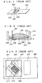
- engraved recesses (characters and bar codes) 202, 202', 203, ⁇ are made, as shown in Fig. 1, on a bar code label 201 made of a metal such as iron and the recesses are magnetically detected by means of a ferromagnetic magnetic resistance device (will be referred to as "MR device” hereinafter) and a permanent magnet.
- MR device ferromagnetic magnetic resistance device
- the head at the bottom of a main body 204 in which the MR device and permanent magnet are integrally incorporated is swept on the engraved bar code label 201 to read the recess pattern consisting of the recesses 202, 202', 203, ⁇ .
- the principle of this bar code reading will be discussed below:
- the engraved recesses 202, 202', 203, ⁇ are magnetized by the DC magnetic formed by the permanent magnet.
- the magnetic field formed by these magnetized recesses causes the magnetic flux distribution over the recesses to change and this change of the magnetic flux distribution results in a resistance change of the MR device.
- the resistance change is passed to the signal processing circuit provided in the head of the main body 204 in which they are converted into a binary-coded signal (0 or 1) correspondingly to the code represented by the recess pattern. This binary-coded signal is supplied to the decoder for recognition of the bar code pattern.
- the conventional head of the magnetic bar code reader operating on the above-mentioned principle has a tip of which the structure will be discussed below with reference to Fig. 2. Namely, for an electrical connection between an input wire of an MR device 206 made on a printed circuit board 205 through a well-known IC manufacturing process and an external lead wire 207 through which a current is supplied to detect a magnetic field change as a voltage, the circuit board 205 is connected to an electrode 209 by means of a bonding wire 208 and the external lead wire 207 is spot-joined to the electrode 209 by means of a solder joint 210.
- the electrode 209 and circuit board 205 are attached to an internal substrate 211. Further, the internal substrate 211 and electrode 209 are attached to a head frame 212 and sealed from below with a coating film 213.
- a permanent magnet 214 provided for exciting is attached to the internal substrate 211 and sealed with a coating film 215.
- a generally square MR device is used as shown in Fig. 3.
- a magnetic resistance film 217 formed on a circuit board 216 made of, for example, a glass is provided in such a structure that it is folded back in parallel to the lateral side of the circuit board 216.
- a plurality of such magnetic resistance films is provided as cascade-connected.
- the number of the magnetic resistance films thus provided is such that the whole resistance will be on the order several kiloohms.
- a current-supplying electrode 218 is provided on either end of the magnetic resistance film 217 in such a manner that an ohmic contact can be assured.
- these patterns are so set as to form together a generally square shape in many cases.
- the above-mentioned MR device is inclined more than 30 deg. with respect to bar code recesses 219 and a parmanent magnet 220 which applies a biasing magnetic field is provided on the MR device to make a head 221 which will be swept on recesses 223, engraved in the form of bar code in an iron sheet 222, in a direction perpendicular to the length of the engraved recesses 223, thereby reading the bar code.
- a bar code label made of any other metal sheet than the iron sheet is so resistant against contamination or staining that even when the label surface is stained with a dirt or the like, it can be washed with water to remove such dirt.
- the label in case the label is made of an iron sheet, it will be rusty and thus corroded.
- any iron-sheet bar code label is not suitably usable in a place where the atmosphere is very salty.
- the bonding wire 208 is provided as bonded to the electrode 205 on the substrate (semiconductor substrate) of the MR device 206 by using an ultrasonic bonder or the like, a air gap d (about 0. 3 mm) must be provided under these elements.
- This air gap causes the strength of the magnetic lines of force produced by the engraved recesses, that is to be detected by the MR device, to be extremely small.
- the MR device has only a low sensitivity to the magnetic lines of force formed by the bar code recesses.
- the sensitivity of the MR device is found very low. For example, when about 0.1 mm is off the label surface in relation to a pattern of minimum recesses of 0.5 mm, the head can hardly read the code represented by the recess pattern.
- the width of the MR device will be about 0.7 mm to 0.85 mm and thus it is apparent that the MR device cannot read any engraved recess of 0.5 mm in minimum width. Also even if a bar code reading head is constructed with the MR device not inclined 45 deg. (the biasing magnetic field may be applied from a direction inclined 45 deg.) but directed longitudinally of the engraved recesses at the sacrifice of the sensitivity to some extent, any common magnetic sensor element having a large width, if fitted, in the head cannot read a high resolution (namely, narrow) bar code recess pattern.
- US-A-4 520 311 discloses a device for measuring a current.
- the device has two current to pulse sequence transducers. A reference current is passed through one transducer and the current to be measured is passed through the other. The magnetic field produced by the two transducers are compared.
- the present invention provides a bar code reader for reading a bar code label of a ferromagnetic material on which coded information is recorded by engraved recesses, the bar code reader comprising: a magnetic sensor having an magnetic resistance, MR, device, the MR device being composed of a printed circuit board and magnetic resistance films being formed on said circuit board for detecting a magnetic field change due to a bar code label; and a permanent magnet so disposed that an axis between the poles thereof is inclined by 45° with respect to the length of the films; characterised in that the bar code reader further comprises an amplifying means for amplifying the output signal from said magnetic sensor, a differentiating means for differentiating the output signal from said amplifying means, and comparison means for comparing the output signal from said differentiating means with a reference voltage and for coding the result; and in that said magnetic resistance films are inclined by about 45° with respect to the lateral side of said circuit board, and are parallel to each other and cascade-connected in series to each other.
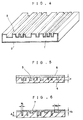
- Fig. 4 shows a bar code label, this engraved bar code label comprising a base 1 having formed a protective film 2 or the outer surface thereof.
- the base 1 is a square sheet made of a material such as iron or the like, the sheet having the top and bottom surfaces thereof machined like a mirror surface to minimize the surface irregularity.
- the base 1 has formed as engraved on the top surface thereof a record area 3 carrying, for identification, a variety of information on, for example, the name of a unit or force to which a solder belongs or the proprietor, serial number or the line of an outdoor installation such as construction machine, vehicle, gas cylinder, machine part, steel tower or the like.
- the record area 3 consists of recesses different in width from each other correspondingly to various information. The recesses are formed by etching or punching.
- the protective film 2 is provided to protect the record area 3 for a long term being eroded, and it is selected from among plastic, nickel, lead(Pb) or tin (Sn).
- the stainless material such as plastic, nickel or the like is applied as a thin film on the entire surface of the base 1.
- the lead or tin is applied as plated on the entire surface of the base 1.
- the protective film 2 is applied on the entire surface of the base 1. Namely, it can be easily manufactured with less manufacuturing costs.
- Fig. 5 shows a second bar code label.
- This engraved bar code label comprises a film-shaped base 4 made of a ferromagnetic material such as iron (Fe), cobalt(Co). nickel(Ni) or the like and on which a record area 5 is provided which consists of recesses different in width from each other and which are engraved with a predetermined spacing from one to another recess, and a nonmagnetic film 6 so molded in the record area 5 or the base 4 as to completely bury the recesses.
- a ferromagnetic material such as iron (Fe), cobalt(Co). nickel(Ni) or the like
- a record area 5 which consists of recesses different in width from each other and which are engraved with a predetermined spacing from one to another recess
- a nonmagnetic film 6 so molded in the record area 5 or the base 4 as to completely bury the recesses.
- the base 4 in this second embodiment has the top and bottom surfaces thereof machined with a high precision like a mirror face to prevent any read error form taking place.
- the record area 5 in this embodiment has engraved in the top surface of the base 4 recesses each having a predetermined width corresponding to an information to be recorded, spaced a predetermined distance between adjoining one and engraved to a predetermined depth d .
- this record area 5 is applied with a magnetic field from outside by the magnet or the like, the magnetic lines of force are concentrated laterally of the recesses, resulting in a distortion of the distribution of the magnetic lines of force.
- the nonmagnetic film 6 is a mold of a nonmagnetic material such as plastic or the like to a predetermined thickness to the record area 5.
- Fig. 6 shows a third engraved bar code label, in which the depth d 1 of a recess 7 of smaller width W 1 is larger than the depth d 2 of a one 7 of larger width W 2 , namely, d 1 >d 2 .
- the depth d 2 is smaller than the depth d 1 , it is possible to prevent the magnetic field near the wide recess from being distorted largely, which leads to less distortion of the magnetic field on the adjoining narrow recess.
- the recess width is changed correspondingly to the recess width; thus, the output waveform corresponding to the recess 7 is less distorted during the information reading and thus a high information density, namely, high resolution bar code label can be read accurately.
- the record area consists of bar-like recesses, but the present invention is not limited to this shape of recess but the recesses may be formed in the shape of, for example, a predetermined symbol, character or the like.
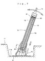
- Fig. 7 shows a comparative bar code reader.
- the bar code reader comprises a main body 9 and a head 10 to magnetically read a bar code label 8 in which information are magnetically recorded, for recognition of the information.
- the bar code label 8 is the same as the first bar code label. That is, this bar code label 8 has a record area consisting of recesses engraved in a magnatic base, each having a predetermined width corresponding to an information to be recorded, and they being spaced a predetermined distance from each other.
- the bar code label 8 is used as securely attached on the bottom of a concave portion 11a or the like of a particular commodity, for example, an equipment 11 which is used outdoors.
- the main body 9 comprises a long cylinder in which there are provided printed circuit board 12 having mounted thereon electrical elements (not shown) forming together a circuit to process a signal in a predetermined manner and a shielding means 13 of preventing a magnetic interference from taking place between these electrical elements and the exterior of the main body 9 and a noise due to electric field coupling from occurring, and it is connected to a decoder (not shown) outside the main body 9 by means of a cable 14.
- the circuit board 12 has formed thereof a signal processing circuit, of which the circuit configuration will be seen from Fig. 8, consisting of an amplification circuit 15, differentiation circuit 16, comparison circuit 17 and a polarity inversion circuit 18.
- the amplification circuit 15 amplifies an electric signal resulted from a magnetic resiscance change caused by the MR device which will be discussed later.
- the amplification circuit 15 is composed of two stage of amplifiers each made of a linear IC and has the input thereof connected to a bridge circuit in which the MR device is provided and the output thereof connected to the input of the differentiation circuit 16.
- the electric signal amplified by the amplification circuit 15 is wave-shaped in a predetermined manner for identification of the recess width in the record area on the bar code label 8.
- the differentiation circuit 16 has the input thereof connected to the output of the amplification circuit 15 and the output thereof connected to the input of the comparison circuit 17.
- the comparison circuit 17 responds to the widths of each recess in the record area which are identified by the differentiation circuit 16 and converts an analog signal of a predetermined waveform into a digital signal of a rectangular waveform or the like.
- a linear IC is used as the comparator, and the comparison circuit 17 has the input thereof connected to the output of the differentiation circuit 16 and the output thereof connected to the input of the polarity inversion circuit 18.
- the polarity inversion circuit 18 returns to the initial state the phase of the output waveform shifted 90 deg. during wave-shaping in the differentiation circuit 16, namely, to the phase corresponding to the recesses in the record area on the bar code label.
- This inversion circuit 18 consists of two stages of transistors, of which the input is connected to the output of the comparison circuit 17 while the output is connected to the input of the decoder circuit (not shown) outside the main unit 9.
- the elongated circuit board 12 having mounted thereon various electrical elements forming these circuits is installed as fitted at the lower end thereof in a recess 19a formed on the top of a retainer 19 provided as erected on the bottom of a housing 19 as shown in Fig. 9, and also as close-fitted at the upper end thereof in a resess formed in a retainer 21 forced under the resilience of a spring 20 as shown in Fig. 7.
- circuits may be formed each by a combination of electrical elements such as individual IC, resistor, capacitor and so forth and disposed on the circuit board, and also that these elements may be combined into a hybrid IC or monolithic IC and mounted on the circuit board.
- the head 10 is installed pivotably and movably to the main body 9, and composed of a base 23 installed to the bottom of the housing 9a of the main body 9 by means of a pivoting/moving mechanism 22, a reading means 24 provided on the base 23, and a skirt 32 as shown in the Fig. 10.
- the pivoting/moving mechanism 22 is provided to smoothly scan the head 10 for reading the bar code label 8 and to freely pivot and vertically move the head 10 in relation to the housing 9a of the main body 9.
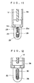
- the pivoting/moving mechanism 22 comprises, as shown in Fig.
- a coupling member 25 having an elongated hole 25a and secured to the bottom of the housing 9a, a bracket 27 pivotably supporting a pivot shaft 26 through the elongated hole 25a in the coupling member 25 and provided upright on the base 23, and a spring 29 applying a resilient force toward the pivot shaft 26 in the elongated hole 25a by means of a pusher 28 (as seen from Fig. 11).
- a pusher 28 as seen from Fig. 11
- the pivot shaft 26 is applied with a resilient force by the coil spring 29 in this embodiment, this is just an example.
- the bar code reader is not limited to this embodiment but, for example, a plurality of generally inverted V-shaped leaf springs 30 may be used in place of the coil spring, as shown in Fig. 12. As the reading means 24, a MR device is employed.
- an MR device and predetermined resistors are combined to form a bridge circuit.
- the output of the bridge circuit is connected to the input of the amplification circuit 15 provided on the circuit board 12 by means of an interconnecting cord passed through a hole 9b opened at the bottom of the housing 9a.
- the MR device is so designed that the internal resistance changes corresponding to the size of external magnetic field and it is made of a silicon compound semiconductor, ferromagnetic film (metal) or the like.
- the bridge circuit comprising the MR device delivers a signal of a waveform of which the extreme value fall on each of the recess boundaries as seen from Fig. 14.
- this output signal from the bridge circuit is amplified by the amplification circuit and then supplied to the differentiation circuit 16 which in turn will deliver to the comparison circuit 17 a signal of a waveform phase-shifted from the output waveform from the bridge circuit and precisely corresponding to the recesses on the bar code label 8 as shown in Fig. 15.
- the comparison circuit 17 delivers a coded digital signal corresponding to the shape of the recesses in the bar code label 8 as shown in Fig. 16.
- the bar code label 8 is secured in, for example, a narrow concave portion 11a as shown in Fig. 7, it can be positively scanned and read by the head by pivoting the main body 9.
- Fig. 17(a) shows the construction of a second comparative bar code reader
- Fig. 17(b) shows the shapes of a main body 33 and head 34 of this bar code reader.
- the bar code reader has a pen head-type structure to sweep the bar code label 101 (basically the one shown in Fig. 1) and read the code thereon.
- the head at the tip of the reader is built in a head frame 35 as shown in Fig. 17(a).
- the head frame 35 is an opened casing having a cut 35a formed at the end thereof.
- a permanent magnet 36 is installed as supported on the bottom 35b within the head frame 35 and a printed circuit board on which a MR device 37 is formed by predetermined IC manufacturing process is provided as supported on an internal lead wire 38 in a hole 35c and facing the end of the head frame 35.
- the internal lead wire 38 is formed on a resin film 38 by patterning.
- the resin film 39 is fitted in the cut 35a and the surface thereof is so shaped as to be flush with the end of the head frame 35.
- the internal lead wire 38 and circuit board 40 are joined to each other by means of a bumping material 41.
- the bumping material 41 is previously attached to the internal lead wire 38 and connected, as pressed from the resin film side by means of a bonding tool, to an input wire 37' of the MR device 37 laid on the circuit board 40.
- the input wire 37' is made of Au or the like while the internal lead wire 38 is of Cu or the like.
- the resin film 39, internal lead wire 38 and circuit board 40 are coated with a resin film 42 for a protection from the environment and also for prevention of their separation.
- a resin film 42 for a protection from the environment and also for prevention of their separation.
- the permanent magnet 36 is mechanically fixed to the head frame 35 by means of the resin coating 45.
- An external lead wire 46 through a current is suppled to the MR device 37 and by which a resistance change is detected is passed through the bottom 35b and solder-joined to the internal lead wire 38.
- the resin film 39, internal lead wire 38 and bumping material 41 are about 0.1 mm, 0.05 mm and 0.01 mm thick, respectively.
- the gap between the surface of the resin film 39, namely, the end of the detector (end of the head frame). and the surface of the MR device (circuit board surface) is about 0.15 mm. This gap size is nearly a half of the conventional reader in which a bonding wire is used. Because of the fact that the strength of magnetic field attenuates in proportion to one/square or one/cube of distance, the sensitivity of detection is four times higher than in the conventional reader. Fig.
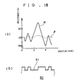
- FIG. 18(a) shows the magnatic resistance change when the reader is swept on a bar code label 50 (with minimum recess pattern of 0.5 mm) made of a metal.
- Fig. 18(b) shows the relation between the recesses engraved on the bar code label 50 and the magnetic resistance change.
- the resistance change characteristic ⁇ is a one obtained when the bar code reader according to the present invention was used while the characteristic ⁇ is a one obtained by using the conventional reader. In the reader the magnetic resistance changes more greatly than in the bar code reader of the conventional structure. Even when the head 34 is swept at a height of about 0.1 to 0.2 mm above the top surface of the bar code label, the code could be accurately read.
- the bar code reader can read an engraved record in a bar code label even when the latter is somewhat stained with an oil, dust or minute metal piecses. Since being able to catch up with any fluctuation of sensitivity (approximately 0.1 to 0.2 mm), the bar code reader invention is highly reliable.
- the MR device according to the present invention is composed of magnatic resistance films 48 formed on the surface of the circuit board 47 and which is made of Si, glass or the like, and an electrode 49 of Au or the like through which a current is supplied to the magnetic resistance films 48.
- the magnetic resistance films 48 are formed in vertical parallel to each other as inclined about 45 deg. with respect to the lateral side of the circuit board 47, and they are cascade-connected in series to each other by means of electrically conductive films 48a.
- the magnetic resistance films 48 since the width (lateral length) of the magnetic resistance films 48 which detect a magnatic field change is reduced to the longitudinal length of the films, nemely, 1/2 (about 70%), the magnetic resistance films 48 will not extend on both the opposite sides of engraved recesses 51 in a same bar code label 50 as in the aforementioned comparative example, so the bar code label 50 can be read, even if the engraved recesses 51 in the bar code label 50 form a high density pattern.
- each of the magnetic resiscance films 48 is, for example, 0.5 to 0.6 mm long, its width is only 0.35 to 0.42 mm. Namely, it is possible to read bar code recesses each of 0.5 mm in width by the head according to this embodiment.
- the structure of the head according to the present invention is advantageous for reading a high resolution pattern.
- the present invention is also advantageous for providing a high sensitive reader.
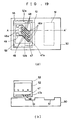
- a permanent magnet 52 used in pair with the aforementioned MR device is positioned as will be discussed below. Namely, for biasing the magnetic resistance films 48 of the MR device, the permanent magnet 52 is so disposed that the poles 52a and 52b thereof are shifted 45 deg. with respect to the length of the films 48. As shown in Fig. 19, the permanent magnet 52 is mounted on the circuit board 47 of the MR device in such a manner that the poles 52a and 52b are positioned vertically, that is, longitudinally of the recesses 51. Thus, the MR device can be set in the most sensitive, optimum biased state. At this time, the magnetic resistance films 48 are vertically biased.
- the magnetic field change due to the recess edges are applied in the sweeping direction so that the MR device will cause the magnetic field change to incline in a direction within a range of +/-45 deg., thus the magnetic field will fully change within a linear magnetic resistance change range of the MR device.
- the bar code can be read in a wide dynamic range.
- the bar code reader according to the present invention is highly reliable.
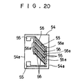
- Fig. 20 shows the structure of an MR device according to a second embodiment of the present invention.
- the lower one (55) of current-supplying electrodes 55 and 55 is extended on a printed circuit board 54 from one lateral side 54a of the circuit board toward the other lateral side 54a, magnetic resistance films 56 are disposed as inclined 45 deg., the lowest one of the films 56 is extended to and connected to the lower electrode 55, and the magnetic resistance films 56 are cascade-connected to each other with the electrode 55 interposed between adjoining films 56.
- the current is supplied only in one derection to the magnatic resistance films 56, no resistance change due to a magnetic field depending upon the direction of the current will occur. so that a stable detection of magnetic field change is assured.
- the operating principle and other effect of this embodiment are quite the same as those in the aforementioned first embodiment.
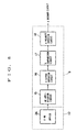
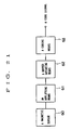
- Fig. 21 is a block diagram of a bar code reader according to the third embodiment of the present invention.
- the bar code reader according to this embodiment comprises a magnetic sensor 60 having an MR device as essential element, an amplifying means 61 to amplify an analogue voltage waveform, output from the magnetic sensor 60, a differentiating means 62 to detect a start signal of the amplified analogue voltage waveform and also to differentiate this analogue voltage waveform, and a coding means 63 to shape the differentiated signal and extract a code signal therefrom.
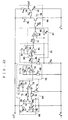
- Fig. 22 is also a block diagram showing the component circuits of the bar code reader according to the third embodiment of the present invention.
- an output voltage from a bridge circuit 68 consisting of an MR device 64, resistors 65, 66 and 67 and thus forming the magnetic sensor is supplied to a differential amplification circuit 69 which forms, together with a noninverted amplification circuit 70, the avove-mentioned amplifying means 61.
- the differential amplification circuit 69 is composed of a linear IC 73 having a negative feedback circuit consisting of a capacitor 71 and resistor 72, and three input resistors 74, 75 and 76.
- This differential amplification circuit 69 amplifies a differential voltage of a signal supplied to the negative and positive terminals of tile linear IC 73 from the bridge circuit 68 and delivers it to the noninverted amplification circuit 70.
- This circuit 70 consists of a linear IC 79 having a negative feedback circuit composed of a capacitor 77 and resistor 78, and an input resistor 80.
- the output signal from this noninverted amplification circuit 70 is supplied as input to a differentiation circuit 81 forming the differentiating means 62.
- the differentiation circuit 81 consists of a linear IC 84 having a negative feedback circuit composed of a capacitor 82 and resistor 83, a series circuit composed of a resistor 85 and capacitor 86 connected to the negative terminal of the linear IC 84, and a reference voltage source connected to the positive terminal.
- This differentiation circuit 81 delivers to a comparison circuit 87 forming the coding means 63 an output signal phase-shifted 90 deg. with respect to the input signal.
- the comparison circuit 87 consists of a linear IC 90 having a positive feedback circuit formed by a resistor 89, a resistor 91 connected to the negative terminal of the linear IC 90, and a reference voltage source connected to the positive terminal of the linear IC 90.
- This comparison circuit 87 compares an input signal supplied to the negative terminal with the reference voltage applied to the positive terminal and delivers an output pulse "H” or "L” to a signal output circuit 88.
- the signal output circuit 88 is formed by two transistors 92 and 93 so connected as to turn on and off in such a manner that when one of the transistors turns on, the other turns off and when the one turns off, the other turns on. More particularly, when the transistor 92 is turned on by a pulse "H" supplied to the base terminal of the transistor 92 through a resistor 94, a current flows from the collector of the transistor 92 the emitter thereof through a resistor 95 connected to the connector terminal thereof. As the result, the base voltage of the transistor 93 connected to the collector terminal through a resistor 96 drops, so that the transistor 93 is turned off.
- the output pulse from the comparison circuit 87 is delivered as a pulse of a same polarity, having an improved capability of supplying a current to a load, in the signal output circuit 88.
- Fig. 23 shows the signal waveforms at various portions of the magnetic sensor 60;
- Fig. 23(a) shows the waveform of the output voltage from the bridge circuit 68, corresponding to the shape of the engraved magnetic recesses,
- Fig. 23(b) shows the waveform of the output voltage from the differentiation circuit 82, and
- Fig. 23(c) shows the coded pulse group, the output from the comparison circuit 87.
- the magnatic field is changed by the engraved recessed (the magnatic field becomes the maximum and minimum at the recess edges) and the change amount appears as a change of the output voltage of the bridge circuit 68.
- the output signal resulted from the amplification of the output from the bridge circuit 68 is amplified for the gain of amplification, further phase-converted and appears as a change in duration of the output pulse delivered from the comparison circuit 87.
- the recess width is proportional to the output pulse width. So, the bar code reader using the magnetic sensor 60 according to the present invention can be used to read the bar code formed by a plurality of recesses different in width and spacing between them, nemely, the information recorded in the record area.
- the magnetic sensor thus constructed is evidently different in structure from the conventional ones used in the speedometer, printer and the like.
- the magnetic sensor according to the present invention can magnetically detect and reproduce a pattern on a magnetic bar code label with a high effectiveness and efficiency.
- the pattern on the bar code label (metallic) can be read accurately.
- the magnetic sensor may be made in the form of a single fold or a single chip. Since the mold and chip are a very small device, a handy bar code reader can be designed.
- a bar code reader uses an MR device consisting of obliquely extending, cascade-connected magnetic resistance films, permitting to read a high density bar code pattern with a high sensitivity.
- the MR device By adopting a bar code detector in which a permanent magnet is so disposed as to provide a biasing from a direction shifted about 45 deg. with respect to the length of the MR device, the MR device can be operated in a wide dynamic range, thereby permitting a high sensitivity reading.
- the bar code reader of the present invention provides for a highly reliable bar code reading system.
- a bar code reader incorporates a magnetic sensor and thus provides for a bar code reading system highly durable, not easily affectable by the operating environment, hardly influenced by staining or impair during storage or transportation and which is easy to handle in reading information from bar codes or the like.
Landscapes
- Engineering & Computer Science (AREA)
- Physics & Mathematics (AREA)
- General Physics & Mathematics (AREA)
- Theoretical Computer Science (AREA)
- Artificial Intelligence (AREA)
- Computer Vision & Pattern Recognition (AREA)
- Measuring Magnetic Variables (AREA)
- Magnetic Record Carriers (AREA)
- Magnetic Heads (AREA)
- Transmission And Conversion Of Sensor Element Output (AREA)
Description
- The present invention relates to a bar code label in which information on each of various commodities, outdoor installations or individuals are recorded as engraved in the form of characters and bar codes.
- The bar code label is well known and widely used as attached on the surface of a box or package in which a commodity or delivery is packed. The bar code label carries a variety of information, as coded in the form of bars different in width from one another, on such commodity. The information are used for a higher efficiency and less labor in sales calculation, inventory control or assortment.
- Generally, such bar code is black bars printed on the white surface of a bar code label.
- If the label surface is stained with an oil or dirt or if the blackness of the coded bars fades, the information recorded in the bar code label cannot possibly be read positively and accurately. Particularly, there is a problem in reading the bar code label outdoors.
- Recently, a magnetic bar code reading system has been proposed which can be used in any environment. In this system engraved recesses (characters and bar codes) 202, 202', 203, ··· are made, as shown in Fig. 1, on a
bar code label 201 made of a metal such as iron and the recesses are magnetically detected by means of a ferromagnetic magnetic resistance device (will be referred to as "MR device" hereinafter) and a permanent magnet. More particularly, the head at the bottom of amain body 204 in which the MR device and permanent magnet are integrally incorporated is swept on the engravedbar code label 201 to read the recess pattern consisting of therecesses - When the head is placed on the engraved
bar code label 201, the engravedrecesses main body 204 in which they are converted into a binary-coded signal (0 or 1) correspondingly to the code represented by the recess pattern. This binary-coded signal is supplied to the decoder for recognition of the bar code pattern. - The conventional head of the magnetic bar code reader operating on the above-mentioned principle has a tip of which the structure will be discussed below with reference to Fig. 2. Namely, for an electrical connection between an input wire of an
MR device 206 made on a printedcircuit board 205 through a well-known IC manufacturing process and anexternal lead wire 207 through which a current is supplied to detect a magnetic field change as a voltage, thecircuit board 205 is connected to anelectrode 209 by means of abonding wire 208 and theexternal lead wire 207 is spot-joined to theelectrode 209 by means of asolder joint 210. Theelectrode 209 andcircuit board 205 are attached to aninternal substrate 211. Further, theinternal substrate 211 andelectrode 209 are attached to ahead frame 212 and sealed from below with acoating film 213. Apermanent magnet 214 provided for exciting is attached to theinternal substrate 211 and sealed with acoating film 215. - As the conventional sensor of the magnetic bar code reader operating on the above-mentioned principle, a generally square MR device is used as shown in Fig. 3. As seen, a
magnetic resistance film 217 formed on acircuit board 216 made of, for example, a glass is provided in such a structure that it is folded back in parallel to the lateral side of thecircuit board 216. For a high magnetic sensitivity, a plurality of such magnetic resistance films is provided as cascade-connected. Usually, the number of the magnetic resistance films thus provided is such that the whole resistance will be on the order several kiloohms. Furthermore, a current-supplyingelectrode 218 is provided on either end of themagnetic resistance film 217 in such a manner that an ohmic contact can be assured. For a higher yield of manufacture with a reduced IC area, these patterns are so set as to form together a generally square shape in many cases. - In a magnetic bar code reader, the above-mentioned MR device is inclined more than 30 deg. with respect to
bar code recesses 219 and aparmanent magnet 220 which applies a biasing magnetic field is provided on the MR device to make ahead 221 which will be swept onrecesses 223, engraved in the form of bar code in aniron sheet 222, in a direction perpendicular to the length of the engravedrecesses 223, thereby reading the bar code. - A bar code label made of any other metal sheet than the iron sheet is so resistant against contamination or staining that even when the label surface is stained with a dirt or the like, it can be washed with water to remove such dirt. However, in case the label is made of an iron sheet, it will be rusty and thus corroded. Particurarly, any iron-sheet bar code label is not suitably usable in a place where the atmosphere is very salty.
- In the head having the structure shown in Fig. 2, since the
bonding wire 208 is provided as bonded to theelectrode 205 on the substrate (semiconductor substrate) of theMR device 206 by using an ultrasonic bonder or the like, a air gap d (about 0. 3 mm) must be provided under these elements. This air gap causes the strength of the magnetic lines of force produced by the engraved recesses, that is to be detected by the MR device, to be extremely small. In other words, the MR device has only a low sensitivity to the magnetic lines of force formed by the bar code recesses. When the head is off the bar code label, the sensitivity of the MR device is found very low. For example, when about 0.1 mm is off the label surface in relation to a pattern of minimum recesses of 0.5 mm, the head can hardly read the code represented by the recess pattern. - In the bar code reader having a magnetic sensor of a structure shown in Fig. 3, since the
magnetic resistance film 217 occupies so large inside the reader as extends fully across one engraved recess, so the changes of magnetic field in opposite directions at the right and left recess edges cancels the magnetic resistance change of the MR device Thus, this reader cannot read any high resolution engraved bar code composed of narrow recesses. For example a common MR device of 0.5 to 0.6 mm in length and width should preferably be inclined 45 deg. with respect to the length of the recesses to apply a biasing magnetic field longitudinally of the recesses in order to read the bar code with a high sensitivity. In this case, however, the width of the MR device will be about 0.7 mm to 0.85 mm and thus it is apparent that the MR device cannot read any engraved recess of 0.5 mm in minimum width. Also even if a bar code reading head is constructed with the MR device not inclined 45 deg. (the biasing magnetic field may be applied from a direction inclined 45 deg.) but directed longitudinally of the engraved recesses at the sacrifice of the sensitivity to some extent, any common magnetic sensor element having a large width, if fitted, in the head cannot read a high resolution (namely, narrow) bar code recess pattern. - US-A-4 520 311 discloses a device for measuring a current. The device has two current to pulse sequence transducers. A reference current is passed through one transducer and the current to be measured is passed through the other. The magnetic field produced by the two transducers are compared.
- Reference is made to copending applications EP-A-0 714 070, EP-A-0 714 071, EP-A-0 714 072.
- The present invention provides a bar code reader for reading a bar code label of a ferromagnetic material on which coded information is recorded by engraved recesses, the bar code reader comprising: a magnetic sensor having an magnetic resistance, MR, device, the MR device being composed of a printed circuit board and magnetic resistance films being formed on said circuit board for detecting a magnetic field change due to a bar code label; and a permanent magnet so disposed that an axis between the poles thereof is inclined by 45° with respect to the length of the films;
characterised in that the bar code reader further comprises an amplifying means for amplifying the output signal from said magnetic sensor, a differentiating means for differentiating the output signal from said amplifying means, and comparison means for comparing the output signal from said differentiating means with a reference voltage and for coding the result; and in that said magnetic resistance films are inclined by about 45° with respect to the lateral side of said circuit board, and are parallel to each other and cascade-connected in series to each other. - These and other objects and advantages of the present invention will be better understood from the following description made, by way of example, of the embodiments of the present invention with reference to the drawings:
- Fig. 1 is a schematic illustration of the essential part of a conventional bar code reader;
- Fig. 2 is also a schematic illustration showing the construction of the head of the conventional bar code reader;
- Fig. 3 schematically illustrates the construction of the conventional bar code reader having a MR device;
- Fig. 4 is a perspective view of a bar code label;
- Fig. 5 is a sectional view of a second bar code label;
- Fig. 6 is a sectional view of a third bar code label;
- Fig. 7 is a sectional view of a comparative bar code reader;
- Fig. 8 is a block diagram of the circuitry in the bar code reader shown in Fig. 7;
- Fig. 9 is a sectional view taken along the line I-I in Fig. 7:
- Fig. 10 is a sectional view, enlarged in scale, of the main body and head of the bar code reader of Fig. 7;
- Fig. 11 is a sectional view of the connection between the main body and head in the bar code reader of Fig. 7;
- Fig. 12 is a sectional view of a variant of the connection between the main body and head in the bar code reader of Fig. 7;
- Fig. 13 graphically shows the relation between the sweep time and recess positions in the bar code label when the latter is read by the bar code reader of Fig. 7;
- Fig. 14 to 16 show waveforms of signals delivered from the bridge circuit, differentiation circuit and comparison circuit, respectively, when the bar code label is read by the bar code reader of Fig. 7; the waveforms showing the changes of the respective signals as the time passes;
- Fig. 17(a) schematically shows the construction of the head of a second comparative bar code reader;
- Fig. 17(b) is a perspective view of the pen head in which the head shown in Fig. 17(a) is built;
- Fig. 18(a) shows the resistance charge characteristic of the MR device when the head sweeps on the bar code label;
- Fig. 18(b) shows the positions of the recesses engraved in the bar code label which corresponded to the magnetic resistance change characteristic in Fig. 18(a);
- Fig. 19(a) is a plan view showing the construction of a bar code reader using an MR device according to the first embodiment of the present invention;
- Fig. 19(b) is a sectional view taken along the line A-A' in Fig. 19(a);
- Fig. 20 is a plan view showing the construction of an MR device according to a second embodiment of the present invention;
- Fig. 21 is a block diagram showing the construction of a bar code reader according to a third embodiment of the present invention;
- Fig. 22 is also a block diagram of an internal circuit composing the magnetic sensor in the bar code reader according to a third embodiment of the present invention; and
- Figs. 23(a) to (c) show signal waveforms, respectivety, at various point of the magnetic sensor according to a third embodiment of the present invention;
- Fig. 4 shows a bar code label, this engraved bar code label comprising a
base 1 having formed aprotective film 2 or the outer surface thereof. - The
base 1 is a square sheet made of a material such as iron or the like, the sheet having the top and bottom surfaces thereof machined like a mirror surface to minimize the surface irregularity. Thebase 1 has formed as engraved on the top surface thereof arecord area 3 carrying, for identification, a variety of information on, for example, the name of a unit or force to which a solder belongs or the proprietor, serial number or the line of an outdoor installation such as construction machine, vehicle, gas cylinder, machine part, steel tower or the like. Therecord area 3 consists of recesses different in width from each other correspondingly to various information. The recesses are formed by etching or punching. - The
protective film 2 is provided to protect therecord area 3 for a long term being eroded, and it is selected from among plastic, nickel, lead(Pb) or tin (Sn). The stainless material such as plastic, nickel or the like is applied as a thin film on the entire surface of thebase 1. The lead or tin is applied as plated on the entire surface of thebase 1. - Thus, the
protective film 2 is applied on the entire surface of thebase 1. Namely, it can be easily manufactured with less manufacuturing costs. - Fig. 5 shows a second bar code label. This engraved bar code label comprises a film-shaped
base 4 made of a ferromagnetic material such as iron (Fe), cobalt(Co). nickel(Ni) or the like and on which arecord area 5 is provided which consists of recesses different in width from each other and which are engraved with a predetermined spacing from one to another recess, and anonmagnetic film 6 so molded in therecord area 5 or thebase 4 as to completely bury the recesses. - Similar to the base according to the first embodiment having been discussed above, the
base 4 in this second embodiment has the top and bottom surfaces thereof machined with a high precision like a mirror face to prevent any read error form taking place. - The
record area 5 in this embodiment has engraved in the top surface of thebase 4 recesses each having a predetermined width corresponding to an information to be recorded, spaced a predetermined distance between adjoining one and engraved to a predetermined depth d. When thisrecord area 5 is applied with a magnetic field from outside by the magnet or the like, the magnetic lines of force are concentrated laterally of the recesses, resulting in a distortion of the distribution of the magnetic lines of force. By detecting the components of the distribution in the direction of the distribution width, signals corresponding to the edges of the recesses, and further by decoding the signals, the original record pattern can be recognized and reproduced. - The
nonmagnetic film 6 is a mold of a nonmagnetic material such as plastic or the like to a predetermined thickness to therecord area 5. - Fig. 6 shows a third engraved bar code label, in which the depth d1 of a
recess 7 of smaller width W1 is larger than the depth d2 of a one 7 of larger width W2, namely, d1>d2. - Because the depth d2 is smaller than the depth d1, it is possible to prevent the magnetic field near the wide recess from being distorted largely, which leads to less distortion of the magnetic field on the adjoining narrow recess.
- Therefore, according to this third bar code label, the recess width is changed correspondingly to the recess width; thus, the output waveform corresponding to the
recess 7 is less distorted during the information reading and thus a high information density, namely, high resolution bar code label can be read accurately. - In the aforementioned bar code labels, the record area consists of bar-like recesses, but the present invention is not limited to this shape of recess but the recesses may be formed in the shape of, for example, a predetermined symbol, character or the like.
- Fig. 7 shows a comparative bar code reader. The bar code reader comprises a
main body 9 and ahead 10 to magnetically read abar code label 8 in which information are magnetically recorded, for recognition of the information. - Note that the
bar code label 8 is the same as the first bar code label. That is, thisbar code label 8 has a record area consisting of recesses engraved in a magnatic base, each having a predetermined width corresponding to an information to be recorded, and they being spaced a predetermined distance from each other. Thebar code label 8 is used as securely attached on the bottom of a concave portion 11a or the like of a particular commodity, for example, anequipment 11 which is used outdoors. - The
main body 9 comprises a long cylinder in which there are provided printedcircuit board 12 having mounted thereon electrical elements (not shown) forming together a circuit to process a signal in a predetermined manner and a shielding means 13 of preventing a magnetic interference from taking place between these electrical elements and the exterior of themain body 9 and a noise due to electric field coupling from occurring, and it is connected to a decoder (not shown) outside themain body 9 by means of acable 14. Thecircuit board 12 has formed thereof a signal processing circuit, of which the circuit configuration will be seen from Fig. 8, consisting of anamplification circuit 15,differentiation circuit 16,comparison circuit 17 and apolarity inversion circuit 18. Theamplification circuit 15 amplifies an electric signal resulted from a magnetic resiscance change caused by the MR device which will be discussed later. In this embodiment, theamplification circuit 15 is composed of two stage of amplifiers each made of a linear IC and has the input thereof connected to a bridge circuit in which the MR device is provided and the output thereof connected to the input of thedifferentiation circuit 16. In thisdifferentiation circuit 16, the electric signal amplified by theamplification circuit 15 is wave-shaped in a predetermined manner for identification of the recess width in the record area on thebar code label 8. Thedifferentiation circuit 16 has the input thereof connected to the output of theamplification circuit 15 and the output thereof connected to the input of thecomparison circuit 17. Thecomparison circuit 17 responds to the widths of each recess in the record area which are identified by thedifferentiation circuit 16 and converts an analog signal of a predetermined waveform into a digital signal of a rectangular waveform or the like. In this embodiment, a linear IC is used as the comparator, and thecomparison circuit 17 has the input thereof connected to the output of thedifferentiation circuit 16 and the output thereof connected to the input of thepolarity inversion circuit 18. Thepolarity inversion circuit 18 returns to the initial state the phase of the output waveform shifted 90 deg. during wave-shaping in thedifferentiation circuit 16, namely, to the phase corresponding to the recesses in the record area on the bar code label. Thisinversion circuit 18 consists of two stages of transistors, of which the input is connected to the output of thecomparison circuit 17 while the output is connected to the input of the decoder circuit (not shown) outside themain unit 9. Theelongated circuit board 12 having mounted thereon various electrical elements forming these circuits is installed as fitted at the lower end thereof in a recess 19a formed on the top of aretainer 19 provided as erected on the bottom of ahousing 19 as shown in Fig. 9, and also as close-fitted at the upper end thereof in a resess formed in aretainer 21 forced under the resilience of aspring 20 as shown in Fig. 7. It should be noted that these circuits may be formed each by a combination of electrical elements such as individual IC, resistor, capacitor and so forth and disposed on the circuit board, and also that these elements may be combined into a hybrid IC or monolithic IC and mounted on the circuit board. - The
head 10 is installed pivotably and movably to themain body 9, and composed of a base 23 installed to the bottom of thehousing 9a of themain body 9 by means of a pivoting/movingmechanism 22, a reading means 24 provided on thebase 23, and askirt 32 as shown in the Fig. 10. The pivoting/movingmechanism 22 is provided to smoothly scan thehead 10 for reading thebar code label 8 and to freely pivot and vertically move thehead 10 in relation to thehousing 9a of themain body 9. To this end, the pivoting/movingmechanism 22 comprises, as shown in Fig. 11, acoupling member 25 having anelongated hole 25a and secured to the bottom of thehousing 9a, abracket 27 pivotably supporting apivot shaft 26 through theelongated hole 25a in thecoupling member 25 and provided upright on thebase 23, and aspring 29 applying a resilient force toward thepivot shaft 26 in theelongated hole 25a by means of a pusher 28 (as seen from Fig. 11). Although thepivot shaft 26 is applied with a resilient force by thecoil spring 29 in this embodiment, this is just an example. The bar code reader is not limited to this embodiment but, for example, a plurality of generally inverted V-shapedleaf springs 30 may be used in place of the coil spring, as shown in Fig. 12. As the reading means 24, a MR device is employed. In this embodiment, an MR device and predetermined resistors are combined to form a bridge circuit. The output of the bridge circuit is connected to the input of theamplification circuit 15 provided on thecircuit board 12 by means of an interconnecting cord passed through ahole 9b opened at the bottom of thehousing 9a. Note that the MR device is so designed that the internal resistance changes corresponding to the size of external magnetic field and it is made of a silicon compound semiconductor, ferromagnetic film (metal) or the like. - Next, how each of the circuits involved functions will be discussed below:
- Assume that the bar code reader is used to scan an engraved
bar code label 8 having, for example, a shape (thickness) as shown in Fig. 13. The bridge circuit comprising the MR device delivers a signal of a waveform of which the extreme value fall on each of the recess boundaries as seen from Fig. 14. - Next, this output signal from the bridge circuit is amplified by the amplification circuit and then supplied to the
differentiation circuit 16 which in turn will deliver to the comparison circuit 17 a signal of a waveform phase-shifted from the output waveform from the bridge circuit and precisely corresponding to the recesses on thebar code label 8 as shown in Fig. 15. - Then the
comparison circuit 17 delivers a coded digital signal corresponding to the shape of the recesses in thebar code label 8 as shown in Fig. 16. - Hence, even if the
bar code label 8 is secured in, for example, a narrow concave portion 11a as shown in Fig. 7, it can be positively scanned and read by the head by pivoting themain body 9. - Fig. 17(a) shows the construction of a second comparative bar code reader, and Fig. 17(b) shows the shapes of a
main body 33 andhead 34 of this bar code reader. - The bar code reader has a pen head-type structure to sweep the bar code label 101 (basically the one shown in Fig. 1) and read the code thereon. The head at the tip of the reader is built in a
head frame 35 as shown in Fig. 17(a). Thehead frame 35 is an opened casing having acut 35a formed at the end thereof. According to the present invention, apermanent magnet 36 is installed as supported on the bottom 35b within thehead frame 35 and a printed circuit board on which aMR device 37 is formed by predetermined IC manufacturing process is provided as supported on aninternal lead wire 38 in ahole 35c and facing the end of thehead frame 35. - The
internal lead wire 38 is formed on aresin film 38 by patterning. Theresin film 39 is fitted in thecut 35a and the surface thereof is so shaped as to be flush with the end of thehead frame 35. Theinternal lead wire 38 andcircuit board 40 are joined to each other by means of a bumpingmaterial 41. The bumpingmaterial 41 is previously attached to theinternal lead wire 38 and connected, as pressed from the resin film side by means of a bonding tool, to an input wire 37' of theMR device 37 laid on thecircuit board 40. - The input wire 37' is made of Au or the like while the
internal lead wire 38 is of Cu or the like. - The
resin film 39,internal lead wire 38 andcircuit board 40 are coated with aresin film 42 for a protection from the environment and also for prevention of their separation. There are opened in the bottom 35b of thehead frame 35 circular or square through-holes 43', 44 and 44' through which arein coating 45 is filled to secure theresin film 39 andinternal lead wire 38 to thehead frame 35. - It should be noted that the
permanent magnet 36 is mechanically fixed to thehead frame 35 by means of theresin coating 45. - An
external lead wire 46 through a current is suppled to theMR device 37 and by which a resistance change is detected is passed through the bottom 35b and solder-joined to theinternal lead wire 38. - In the
head 34 of such construction, theresin film 39,internal lead wire 38 and bumpingmaterial 41 are about 0.1 mm, 0.05 mm and 0.01 mm thick, respectively. The gap between the surface of theresin film 39, namely, the end of the detector (end of the head frame). and the surface of the MR device (circuit board surface) is about 0.15 mm. This gap size is nearly a half of the conventional reader in which a bonding wire is used. Because of the fact that the strength of magnetic field attenuates in proportion to one/square or one/cube of distance, the sensitivity of detection is four times higher than in the conventional reader. Fig. 18(a) shows the magnatic resistance change when the reader is swept on a bar code label 50 (with minimum recess pattern of 0.5 mm) made of a metal. Fig. 18(b) shows the relation between the recesses engraved on thebar code label 50 and the magnetic resistance change. The resistance change characteristic α is a one obtained when the bar code reader according to the present invention was used while the characteristic β is a one obtained by using the conventional reader. In the reader the magnetic resistance changes more greatly than in the bar code reader of the conventional structure. Even when thehead 34 is swept at a height of about 0.1 to 0.2 mm above the top surface of the bar code label, the code could be accurately read. - Having a high sensitivity as mentioned above, the bar code reader can read an engraved record in a bar code label even when the latter is somewhat stained with an oil, dust or minute metal piecses. Since being able to catch up with any fluctuation of sensitivity (approximately 0.1 to 0.2 mm), the bar code reader invention is highly reliable.
- Next, an MR device according to a first embodiment of the present invention and a bar code reader using the MR device will be discussed below:
- As shown in Fig. 19, the MR device according to the present invention is composed of
magnatic resistance films 48 formed on the surface of thecircuit board 47 and which is made of Si, glass or the like, and anelectrode 49 of Au or the like through which a current is supplied to themagnetic resistance films 48. Themagnetic resistance films 48 are formed in vertical parallel to each other as inclined about 45 deg. with respect to the lateral side of thecircuit board 47, and they are cascade-connected in series to each other by means of electricallyconductive films 48a. Thus, since the width (lateral length) of themagnetic resistance films 48 which detect a magnatic field change is reduced to the longitudinal length of the films, nemely, 1/2 (about 70%), themagnetic resistance films 48 will not extend on both the opposite sides ofengraved recesses 51 in a samebar code label 50 as in the aforementioned comparative example, so thebar code label 50 can be read, even if the engraved recesses 51 in thebar code label 50 form a high density pattern. When each of themagnetic resiscance films 48 is, for example, 0.5 to 0.6 mm long, its width is only 0.35 to 0.42 mm. Namely, it is possible to read bar code recesses each of 0.5 mm in width by the head according to this embodiment. Further, in case the barcode recess width is made more smaller, the high resolution barcode reading can be assured by shortening the length of each of themagnetic resistance films 48 while increasing the number of thefilms 48 vertically cascade-connected. In the conventional pattern of magnetic resistance films, however, since the films will somewhat overlap on each other even with the vertical cascade connection of them, no high density bar code pattern can be read. Therefore, the structure of the head according to the present invention is advantageous for reading a high resolution pattern. - With the arrangement of the head according to the present invention, the larger the number of magnetic resistance films, the more magnetic film change due to the bar code recesses can be detected with a higher sensitivity. Thus, the present invention is also advantageous for providing a high sensitive reader.
- In a bar code reader according to the present invention, a
permanent magnet 52 used in pair with the aforementioned MR device is positioned as will be discussed below. Namely, for biasing themagnetic resistance films 48 of the MR device, thepermanent magnet 52 is so disposed that thepoles films 48. As shown in Fig. 19, thepermanent magnet 52 is mounted on thecircuit board 47 of the MR device in such a manner that thepoles recesses 51. Thus, the MR device can be set in the most sensitive, optimum biased state. At this time, themagnetic resistance films 48 are vertically biased. When thehead 53 using thepermanent magnet 52 and the MR device in pair with each other is swept in relation to therecesses 51 on thebar code label 50 with thelateral side 47a of the MR device circuit board and that of thepermanent magnet 52 being nearly flush with the longitudinal direction of therecesses 51 as shown in Fig. 19, the magnetic field change due to the recess edges are applied in the sweeping direction so that the MR device will cause the magnetic field change to incline in a direction within a range of +/-45 deg., thus the magnetic field will fully change within a linear magnetic resistance change range of the MR device. Namely, the bar code can be read in a wide dynamic range. Thus, even if the head is swept somewhat above the bar code label, a stable read of the label can be assured since the resulting voltage signal amplitude corresponds to a relatively large magnetic resistance change. - Namely, the bar code reader according to the present invention is highly reliable.
- Fig. 20 shows the structure of an MR device according to a second embodiment of the present invention.
- According to this embodiment, the lower one (55) of current-supplying
electrodes circuit board 54 from onelateral side 54a of the circuit board toward the otherlateral side 54a,magnetic resistance films 56 are disposed as inclined 45 deg., the lowest one of thefilms 56 is extended to and connected to thelower electrode 55, and themagnetic resistance films 56 are cascade-connected to each other with theelectrode 55 interposed between adjoiningfilms 56. Thus, since the current is supplied only in one derection to themagnatic resistance films 56, no resistance change due to a magnetic field depending upon the direction of the current will occur. so that a stable detection of magnetic field change is assured. The operating principle and other effect of this embodiment are quite the same as those in the aforementioned first embodiment. - Next, a third embodiment of the present invention will be discussed below:
- Fig. 21 is a block diagram of a bar code reader according to the third embodiment of the present invention. As seen from Fig. 21, the bar code reader according to this embodiment comprises a
magnetic sensor 60 having an MR device as essential element, an amplifying means 61 to amplify an analogue voltage waveform, output from themagnetic sensor 60, a differentiatingmeans 62 to detect a start signal of the amplified analogue voltage waveform and also to differentiate this analogue voltage waveform, and a coding means 63 to shape the differentiated signal and extract a code signal therefrom. - Fig. 22 is also a block diagram showing the component circuits of the bar code reader according to the third embodiment of the present invention.
- As shown in Fig. 22, an output voltage from a bridge circuit 68 consisting of an MR device 64,
resistors differential amplification circuit 69 which forms, together with anoninverted amplification circuit 70, the avove-mentioned amplifying means 61. - The
differential amplification circuit 69 is composed of alinear IC 73 having a negative feedback circuit consisting of acapacitor 71 andresistor 72, and threeinput resistors differential amplification circuit 69 amplifies a differential voltage of a signal supplied to the negative and positive terminals of tilelinear IC 73 from the bridge circuit 68 and delivers it to thenoninverted amplification circuit 70. Thiscircuit 70 consists of a linear IC 79 having a negative feedback circuit composed of acapacitor 77 and resistor 78, and aninput resistor 80. The output signal from thisnoninverted amplification circuit 70 is supplied as input to adifferentiation circuit 81 forming the differentiatingmeans 62. - The
differentiation circuit 81 consists of alinear IC 84 having a negative feedback circuit composed of a capacitor 82 andresistor 83, a series circuit composed of a resistor 85 andcapacitor 86 connected to the negative terminal of thelinear IC 84, and a reference voltage source connected to the positive terminal. Thisdifferentiation circuit 81 delivers to acomparison circuit 87 forming the coding means 63 an output signal phase-shifted 90 deg. with respect to the input signal. - The
comparison circuit 87 consists of alinear IC 90 having a positive feedback circuit formed by a resistor 89, aresistor 91 connected to the negative terminal of thelinear IC 90, and a reference voltage source connected to the positive terminal of thelinear IC 90. Thiscomparison circuit 87 compares an input signal supplied to the negative terminal with the reference voltage applied to the positive terminal and delivers an output pulse "H" or "L" to asignal output circuit 88. - The
signal output circuit 88 is formed by twotransistors transistor 92 is turned on by a pulse "H" supplied to the base terminal of thetransistor 92 through a resistor 94, a current flows from the collector of thetransistor 92 the emitter thereof through aresistor 95 connected to the connector terminal thereof. As the result, the base voltage of thetransistor 93 connected to the collector terminal through aresistor 96 drops, so that thetransistor 93 is turned off. Thus, the output pulse from thecomparison circuit 87 is delivered as a pulse of a same polarity, having an improved capability of supplying a current to a load, in thesignal output circuit 88. - The functional sequence of the
magnetic sensor 60 will be discussed with reference to Fig. 23. - Fig. 23 shows the signal waveforms at various portions of the
magnetic sensor 60; Fig. 23(a) shows the waveform of the output voltage from the bridge circuit 68, corresponding to the shape of the engraved magnetic recesses, Fig. 23(b) shows the waveform of the output voltage from the differentiation circuit 82, and Fig. 23(c) shows the coded pulse group, the output from thecomparison circuit 87. - When the bar code-like magnetic recesses engraved in the bar code label are magnetized by the magnetic field source such as the permanent magnet or the like provided in the bar code reader, the magnatic field is changed by the engraved recessed (the magnatic field becomes the maximum and minimum at the recess edges) and the change amount appears as a change of the output voltage of the bridge circuit 68.
- The output signal resulted from the amplification of the output from the bridge circuit 68 is amplified for the gain of amplification, further phase-converted and appears as a change in duration of the output pulse delivered from the
comparison circuit 87. - More particularly, the recess width is proportional to the output pulse width. So, the bar code reader using the
magnetic sensor 60 according to the present invention can be used to read the bar code formed by a plurality of recesses different in width and spacing between them, nemely, the information recorded in the record area. - The magnetic sensor thus constructed is evidently different in structure from the conventional ones used in the speedometer, printer and the like. Provided with an extreme value detecting means, the magnetic sensor according to the present invention can magnetically detect and reproduce a pattern on a magnetic bar code label with a high effectiveness and efficiency.
- Thus, even if stained with dirt or the like or somewhat impaired, the pattern on the bar code label (metallic) can be read accurately.
- Furthermore, the magnetic sensor may be made in the form of a single fold or a single chip. Since the mold and chip are a very small device, a handy bar code reader can be designed.
- A bar code reader according to the present invention uses an MR device consisting of obliquely extending, cascade-connected magnetic resistance films, permitting to read a high density bar code pattern with a high sensitivity. By adopting a bar code detector in which a permanent magnet is so disposed as to provide a biasing from a direction shifted about 45 deg. with respect to the length of the MR device, the MR device can be operated in a wide dynamic range, thereby permitting a high sensitivity reading. Namely, the bar code reader of the present invention provides for a highly reliable bar code reading system.
- A bar code reader according to the present invention incorporates a magnetic sensor and thus provides for a bar code reading system highly durable, not easily affectable by the operating environment, hardly influenced by staining or impair during storage or transportation and which is easy to handle in reading information from bar codes or the like.
Claims (2)
- A bar code reader for reading a bar code label of a ferromagnetic material (50) on which coded information is recorded by engraved recesses, the bar code reader comprising:a magnetic sensor (60) having an magnetic resistance, MR, device (54, 64), the MR device (54, 64) being composed of a printed circuit board (47, 54) and magnetic resistance films (48, 56) being formed on said circuit board (47, 54) for detecting a magnetic field change due to a bar code label; anda permanent magnet (52) so disposed that an axis between the poles (52a) thereof is inclined by 45° with respect to the length of the films (48, 56);characterisedin that the bar code reader further comprises an amplifying means (61) for amplifying the output signal from said magnetic sensor (60), a differentiating means (62) for differentiating the output signal from said amplifying means (61), and comparison means (63, 87) for comparing the output signal from said differentiating means (62) with a reference voltage and for coding the result;and in that said magnetic resistance films (48, 56) are inclined by about 45° with respect to the lateral side of said circuit board (54), and are parallel to each other and cascade-connected in series to each other.
- A bar code reader as claimed in claim 1 whereby, in use, the bar code reader is disposed relative to a bar code label such that the permanent magnets (52) is parallel or substantially parallel to a recess (51) of the bar code label, thereby magnetising said bar code recess (51) with a DC magnetic field, a magnetic field change over said recess (51) being detected by the magnetic resistance films.
Priority Applications (3)
| Application Number | Priority Date | Filing Date | Title |
|---|---|---|---|
| EP96100836A EP0714070B1 (en) | 1990-01-31 | 1991-01-28 | Bar code label |
| EP96100838A EP0714072A2 (en) | 1990-01-31 | 1991-01-28 | Bar code label and bar code reader |
| EP96100837A EP0714071B1 (en) | 1990-01-31 | 1991-01-28 | Bar code reader |
Applications Claiming Priority (10)
| Application Number | Priority Date | Filing Date | Title |
|---|---|---|---|
| JP2021795A JPH03226886A (en) | 1990-01-31 | 1990-01-31 | Magnetic bar code detector |
| JP21795/90 | 1990-01-31 | ||
| JP71142/90 | 1990-03-20 | ||
| JP71141/90 | 1990-03-20 | ||
| JP71140/90 | 1990-03-20 | ||
| JP2071140A JPH0786895B2 (en) | 1990-03-20 | 1990-03-20 | Record form reader |
| JP2071142A JPH0679200B2 (en) | 1990-03-20 | 1990-03-20 | Stamp record sheet |
| JP2071141A JPH03269383A (en) | 1990-03-20 | 1990-03-20 | Magnetic sensor and its signal processing system |
| JP287798/90 | 1990-10-25 | ||
| JP2287798A JPH04160691A (en) | 1990-10-25 | 1990-10-25 | Magnetic resistance element and magnetic bar code detector |
Related Child Applications (5)
| Application Number | Title | Priority Date | Filing Date |
|---|---|---|---|
| EP96100836A Division EP0714070B1 (en) | 1990-01-31 | 1991-01-28 | Bar code label |
| EP96100837A Division EP0714071B1 (en) | 1990-01-31 | 1991-01-28 | Bar code reader |
| EP96100836.4 Division-Into | 1991-01-28 | ||
| EP96100837.2 Division-Into | 1991-01-28 | ||
| EP96100838.0 Division-Into | 1991-01-28 |
Publications (2)
| Publication Number | Publication Date |
|---|---|
| EP0440124A1 EP0440124A1 (en) | 1991-08-07 |
| EP0440124B1 true EP0440124B1 (en) | 1997-10-15 |
Family
ID=27520373
Family Applications (4)
| Application Number | Title | Priority Date | Filing Date |
|---|---|---|---|
| EP96100838A Withdrawn EP0714072A2 (en) | 1990-01-31 | 1991-01-28 | Bar code label and bar code reader |
| EP96100836A Expired - Lifetime EP0714070B1 (en) | 1990-01-31 | 1991-01-28 | Bar code label |
| EP91101047A Expired - Lifetime EP0440124B1 (en) | 1990-01-31 | 1991-01-28 | Bar code label and bar code reader |
| EP96100837A Expired - Lifetime EP0714071B1 (en) | 1990-01-31 | 1991-01-28 | Bar code reader |
Family Applications Before (2)
| Application Number | Title | Priority Date | Filing Date |
|---|---|---|---|
| EP96100838A Withdrawn EP0714072A2 (en) | 1990-01-31 | 1991-01-28 | Bar code label and bar code reader |
| EP96100836A Expired - Lifetime EP0714070B1 (en) | 1990-01-31 | 1991-01-28 | Bar code label |
Family Applications After (1)
| Application Number | Title | Priority Date | Filing Date |
|---|---|---|---|
| EP96100837A Expired - Lifetime EP0714071B1 (en) | 1990-01-31 | 1991-01-28 | Bar code reader |
Country Status (3)
| Country | Link |
|---|---|
| US (2) | US5235169A (en) |
| EP (4) | EP0714072A2 (en) |
| DE (3) | DE69127912T2 (en) |
Families Citing this family (28)
| Publication number | Priority date | Publication date | Assignee | Title |
|---|---|---|---|---|
| FR2712420B1 (en) * | 1993-11-08 | 1995-12-15 | Commissariat Energie Atomique | Magnetic read head with multilayer magnetoresistive element and concentrator and method of making the same. |
| US5537431A (en) * | 1994-06-15 | 1996-07-16 | International Business Machines Corporation | Method and apparatus for bar code reading and decoding |
| US5608199A (en) * | 1995-02-02 | 1997-03-04 | All Tech Inspection, Inc. | Method and apparatus for tagging objects in harsh environments |
| JPH08300858A (en) | 1995-05-08 | 1996-11-19 | Dainippon Printing Co Ltd | Information recording medium |
| US5740066A (en) * | 1995-07-03 | 1998-04-14 | Motorola, Inc. | Electrical circuit board and circuit board assembly |
| US6886748B1 (en) | 1996-01-02 | 2005-05-03 | Steven Jerome Moore | Apparatus and method for purchased product security |
| US7364072B1 (en) | 1996-01-02 | 2008-04-29 | Steven Jerome Moore | Apparatus and method for security |
| CA2273815A1 (en) * | 1996-12-02 | 1998-06-11 | Cal Nichols | Tracking system for animal and carcasses |
| IT1294010B1 (en) * | 1996-12-16 | 1999-03-15 | C I M Card Identification Mach | CUSTOMIZATION EQUIPMENT FOR PUNCHING FLAT SUPPORTS. |
| GB2326003B (en) * | 1997-06-07 | 2001-02-28 | Aquasol Ltd | Coding systems |
| DE19910226B4 (en) * | 1999-03-09 | 2007-05-24 | Bruker Biospin Gmbh | Device and method for identifying and identifying a sample vial |
| US7394086B2 (en) * | 2003-07-18 | 2008-07-01 | Yamaha Corporation | Magnetic sensor and manufacturing method therefor |
| JP4989568B2 (en) * | 2008-06-26 | 2012-08-01 | 住友金属工業株式会社 | Two-dimensional code reader, two-dimensional code reading method, manufacturing history information management method for a member having a substantially circular cross section perpendicular to the central axis, and a method for manufacturing the member using the management method |
| EP2489072A4 (en) * | 2009-10-14 | 2014-05-28 | Lockheed Corp | PRINTED CIRCUIT BOARD PROTECTIVE COVER |
| US8947889B2 (en) | 2010-10-14 | 2015-02-03 | Lockheed Martin Corporation | Conformal electromagnetic (EM) detector |
| US8893978B2 (en) * | 2011-03-14 | 2014-11-25 | Ping Cheung Michael LAU | Surface identification system and method, object having an identification code pattern, and code reading apparatus for reading the object |
| US9135543B2 (en) * | 2012-06-20 | 2015-09-15 | Apple Inc. | Compression and obfuscation of three-dimensional coding |
| EP2989582A4 (en) * | 2013-04-24 | 2017-04-05 | Hewlett-Packard Enterprise Development LP | Displacement signatures |
| EP3032985B1 (en) | 2013-08-13 | 2018-01-17 | Colgate-Palmolive Company | Oral care implement |
| US9871897B1 (en) | 2013-09-09 | 2018-01-16 | Apple Inc. | Sensor stack having a graphical element formed by physical vapor deposition |
| US10434603B2 (en) | 2014-06-21 | 2019-10-08 | Apple Inc. | Forming a textured pattern using a laser |
| US10131035B1 (en) | 2014-09-26 | 2018-11-20 | Apple Inc. | Surface finishing |
| US10489697B2 (en) * | 2015-06-30 | 2019-11-26 | Hitachi Automotive Systems, Ltd. | Article and engraving method |
| DE112016002989T5 (en) * | 2015-06-30 | 2018-03-15 | Hitachi Automotive Systems, Ltd. | Managed article and code engraving process |
| EP3543735A4 (en) * | 2016-11-18 | 2020-07-08 | Auto Drive Solutions S.L. | WITH READ-SENSITIVE SENSORS ON RELATIVE MOVEMENT OF BOTH READ CODED MATERIALS |
| US11389903B2 (en) | 2018-03-30 | 2022-07-19 | Apple Inc. | Electronic device marked using laser-formed pixels of metal oxides |
| CN112462144B (en) * | 2019-01-10 | 2022-09-30 | 湖南龙建达电子科技有限公司 | Quantity measuring device and measuring method based on measuring resistance |
| CN112149776B (en) * | 2020-09-30 | 2024-06-21 | 北京小龙潜行科技有限公司 | Visual tag and assembly thereof |
Citations (1)
| Publication number | Priority date | Publication date | Assignee | Title |
|---|---|---|---|---|
| US4520311A (en) * | 1981-05-19 | 1985-05-28 | Lgz Landis & Gyr Zug Ag | Current to pulse-sequence transducer |
Family Cites Families (12)
| Publication number | Priority date | Publication date | Assignee | Title |
|---|---|---|---|---|
| US4044393A (en) * | 1975-07-14 | 1977-08-23 | Upaya, Inc. | Hand guided tape player |
| FR2402252A1 (en) * | 1977-08-30 | 1979-03-30 | Cii Honeywell Bull | PRINTED CHARACTER READING DEVICE |
| JPS5718018A (en) * | 1980-07-07 | 1982-01-29 | Olympus Optical Co Ltd | Magnetic head |
| JPS5775875A (en) * | 1980-10-29 | 1982-05-12 | Kansai Seikou Kk | Method and device for stamping metallic label |
| GB2114795B (en) * | 1981-12-21 | 1985-08-14 | Omron Tateisi Electronics Co | Verifying system |
| FR2546712A3 (en) * | 1983-06-02 | 1984-12-07 | Hermenault Jean Francois | Loop-bar |
| JPS60175186A (en) * | 1984-02-20 | 1985-09-09 | Tokico Ltd | card reader |
| AT399410B (en) * | 1984-07-13 | 1995-05-26 | Erste Wiener Wach & Schliess | DEVICE FOR DETECTING, STORING AND EVALUATING THE DATA OF A CONTROL PROCESS |
| US4698711A (en) * | 1985-10-02 | 1987-10-06 | International Business Machines Corporation | Simplified, shielded twin-track read/write head structure |
| US4860138A (en) * | 1987-11-12 | 1989-08-22 | International Business Machines Corp. | Differentially sensitive single track read/write head design with improved biasing |
| JPH01233675A (en) * | 1988-03-15 | 1989-09-19 | Tokyu Car Corp | Bar code writing system |
| JPH01280593A (en) * | 1988-04-01 | 1989-11-10 | Tomoki Takashima | Pocket-sized information storage card |
-
1991
- 1991-01-28 DE DE69127912T patent/DE69127912T2/en not_active Expired - Fee Related
- 1991-01-28 DE DE69129762T patent/DE69129762T2/en not_active Expired - Fee Related
- 1991-01-28 EP EP96100838A patent/EP0714072A2/en not_active Withdrawn
- 1991-01-28 US US07/647,619 patent/US5235169A/en not_active Expired - Fee Related
- 1991-01-28 EP EP96100836A patent/EP0714070B1/en not_active Expired - Lifetime
- 1991-01-28 DE DE69129763T patent/DE69129763T2/en not_active Expired - Fee Related
- 1991-01-28 EP EP91101047A patent/EP0440124B1/en not_active Expired - Lifetime
- 1991-01-28 EP EP96100837A patent/EP0714071B1/en not_active Expired - Lifetime
-
1992
- 1992-03-16 US US07/852,274 patent/US5268566A/en not_active Expired - Fee Related
Patent Citations (1)
| Publication number | Priority date | Publication date | Assignee | Title |
|---|---|---|---|---|
| US4520311A (en) * | 1981-05-19 | 1985-05-28 | Lgz Landis & Gyr Zug Ag | Current to pulse-sequence transducer |
Also Published As
| Publication number | Publication date |
|---|---|
| EP0714072A2 (en) | 1996-05-29 |
| EP0714071B1 (en) | 1998-07-08 |
| EP0714071A2 (en) | 1996-05-29 |
| EP0714071A3 (en) | 1996-06-12 |
| US5268566A (en) | 1993-12-07 |
| EP0714070A3 (en) | 1996-06-05 |
| DE69129762D1 (en) | 1998-08-13 |
| DE69127912D1 (en) | 1997-11-20 |
| EP0714070A2 (en) | 1996-05-29 |
| DE69129762T2 (en) | 1999-02-18 |
| DE69129763D1 (en) | 1998-08-13 |
| EP0714070B1 (en) | 1998-07-08 |
| EP0714072A3 (en) | 1996-06-05 |
| US5235169A (en) | 1993-08-10 |
| EP0440124A1 (en) | 1991-08-07 |
| DE69129763T2 (en) | 1999-02-18 |
| DE69127912T2 (en) | 1998-03-05 |
Similar Documents
| Publication | Publication Date | Title |
|---|---|---|
| US5235169A (en) | Bar code label and bar code reader | |
| CN1008668B (en) | Magnetoresistive read transducer | |
| US20040012875A1 (en) | Magnetic read head having decode circuitry | |
| GB2134307A (en) | Magnetic head | |
| JP3377539B2 (en) | Magnetoresistive head for reading magnetic ink characters | |
| JPH0712586A (en) | Magnetic measurement system | |
| US5231275A (en) | Bar code reader | |
| JPS5826071B2 (en) | Magnetic transducer for detecting encoded magnetic information and manufacturing method thereof | |
| US5262622A (en) | Bar code reader | |
| US4097910A (en) | Single gap magnetic read head | |
| US4757257A (en) | Magnetoresistive displacement sensor and signal processing circuit | |
| KR19980071451A (en) | Ferromagnetic sensor | |
| HK1009356A1 (en) | Magneto-resistive sensor | |
| HK1009356B (en) | Magneto-resistive sensor | |
| US4862303A (en) | Magnetic instrument for reading telegraphic signals | |
| JPH04504479A (en) | A code carrier, a method for evaluating information on the code carrier, and a coding system using the code carrier for product identification. | |
| US4204315A (en) | Method of producing a magnetic transducer device | |
| JP3774501B2 (en) | Magnetic marker and reading method thereof | |
| JP3067484B2 (en) | Magnetic position and rotation detection element | |
| JPH03226886A (en) | Magnetic bar code detector | |
| US5258603A (en) | Magnetic reading head having a tapered reading opening and/or a tapered reading stylus | |
| JPS6051153B2 (en) | magnetic card reader | |
| JPH0562029A (en) | Magnetic bar code panel | |
| JP2546281B2 (en) | Origin detection part of magnetic head for magnetic encoder | |
| JPH0458174A (en) | Magnetic sensor for detecting marking |
Legal Events
| Date | Code | Title | Description |
|---|---|---|---|
| PUAI | Public reference made under article 153(3) epc to a published international application that has entered the european phase |
Free format text: ORIGINAL CODE: 0009012 |
|
| AK | Designated contracting states |
Kind code of ref document: A1 Designated state(s): AT BE CH DE DK ES FR GB GR IT LI LU NL SE |
|
| RBV | Designated contracting states (corrected) |
Designated state(s): BE CH DE FR GB LI NL |
|
| 17P | Request for examination filed |
Effective date: 19920204 |
|
| 17Q | First examination report despatched |
Effective date: 19941222 |
|
| GRAG | Despatch of communication of intention to grant |
Free format text: ORIGINAL CODE: EPIDOS AGRA |
|
| GRAH | Despatch of communication of intention to grant a patent |
Free format text: ORIGINAL CODE: EPIDOS IGRA |
|
| RAP1 | Party data changed (applicant data changed or rights of an application transferred) |
Owner name: NIPPON ELECTRIC INDUSTRY, CO. LTD. Owner name: NEC CORPORATION |
|
| GRAH | Despatch of communication of intention to grant a patent |
Free format text: ORIGINAL CODE: EPIDOS IGRA |
|
| GRAA | (expected) grant |
Free format text: ORIGINAL CODE: 0009210 |
|
| DX | Miscellaneous (deleted) | ||
| AK | Designated contracting states |
Kind code of ref document: B1 Designated state(s): BE CH DE FR GB LI NL |
|
| REG | Reference to a national code |
Ref country code: CH Ref legal event code: EP |
|
| REG | Reference to a national code |
Ref country code: CH Ref legal event code: NV Representative=s name: RITSCHER & SEIFERT PATENTANWAELTE VSP |
|
| REF | Corresponds to: |
Ref document number: 69127912 Country of ref document: DE Date of ref document: 19971120 |
|
| ET | Fr: translation filed | ||
| PGFP | Annual fee paid to national office [announced via postgrant information from national office to epo] |
Ref country code: NL Payment date: 19980128 Year of fee payment: 8 |
|
| PGFP | Annual fee paid to national office [announced via postgrant information from national office to epo] |
Ref country code: CH Payment date: 19980205 Year of fee payment: 8 |
|
| PGFP | Annual fee paid to national office [announced via postgrant information from national office to epo] |
Ref country code: BE Payment date: 19980320 Year of fee payment: 8 |
|
| PLBE | No opposition filed within time limit |
Free format text: ORIGINAL CODE: 0009261 |
|
| STAA | Information on the status of an ep patent application or granted ep patent |
Free format text: STATUS: NO OPPOSITION FILED WITHIN TIME LIMIT |
|
| 26N | No opposition filed | ||
| PG25 | Lapsed in a contracting state [announced via postgrant information from national office to epo] |
Ref country code: LI Free format text: LAPSE BECAUSE OF NON-PAYMENT OF DUE FEES Effective date: 19990131 Ref country code: CH Free format text: LAPSE BECAUSE OF NON-PAYMENT OF DUE FEES Effective date: 19990131 Ref country code: BE Free format text: LAPSE BECAUSE OF NON-PAYMENT OF DUE FEES Effective date: 19990131 |
|
| BERE | Be: lapsed |
Owner name: NIPPON ELECTRIC INDUSTRY CO. LTD Effective date: 19990131 Owner name: NEC CORP. Effective date: 19990131 |
|
| PG25 | Lapsed in a contracting state [announced via postgrant information from national office to epo] |
Ref country code: NL Free format text: LAPSE BECAUSE OF NON-PAYMENT OF DUE FEES Effective date: 19990801 |
|
| REG | Reference to a national code |
Ref country code: CH Ref legal event code: PL |
|
| PGFP | Annual fee paid to national office [announced via postgrant information from national office to epo] |
Ref country code: DE Payment date: 19991231 Year of fee payment: 10 |
|
| PGFP | Annual fee paid to national office [announced via postgrant information from national office to epo] |
Ref country code: FR Payment date: 20000112 Year of fee payment: 10 |
|
| PGFP | Annual fee paid to national office [announced via postgrant information from national office to epo] |
Ref country code: GB Payment date: 20000126 Year of fee payment: 10 |
|
| PG25 | Lapsed in a contracting state [announced via postgrant information from national office to epo] |
Ref country code: GB Free format text: LAPSE BECAUSE OF NON-PAYMENT OF DUE FEES Effective date: 20010128 |
|
| REG | Reference to a national code |
Ref country code: GB Ref legal event code: 732E |
|
| REG | Reference to a national code |
Ref country code: FR Ref legal event code: CD |
|
| GBPC | Gb: european patent ceased through non-payment of renewal fee |
Effective date: 20010128 |
|
| PG25 | Lapsed in a contracting state [announced via postgrant information from national office to epo] |
Ref country code: FR Free format text: LAPSE BECAUSE OF NON-PAYMENT OF DUE FEES Effective date: 20010928 |
|
| PG25 | Lapsed in a contracting state [announced via postgrant information from national office to epo] |
Ref country code: DE Free format text: LAPSE BECAUSE OF NON-PAYMENT OF DUE FEES Effective date: 20011101 |
|
| REG | Reference to a national code |
Ref country code: FR Ref legal event code: ST |