EP0440139B1 - Hot electron transistor - Google Patents
Hot electron transistor Download PDFInfo
- Publication number
- EP0440139B1 EP0440139B1 EP91101080A EP91101080A EP0440139B1 EP 0440139 B1 EP0440139 B1 EP 0440139B1 EP 91101080 A EP91101080 A EP 91101080A EP 91101080 A EP91101080 A EP 91101080A EP 0440139 B1 EP0440139 B1 EP 0440139B1
- Authority
- EP
- European Patent Office
- Prior art keywords
- barrier layer
- collector
- layer
- emitter
- base
- Prior art date
- Legal status (The legal status is an assumption and is not a legal conclusion. Google has not performed a legal analysis and makes no representation as to the accuracy of the status listed.)
- Expired - Lifetime
Links
Images

Classifications
-
- H—ELECTRICITY
- H10—SEMICONDUCTOR DEVICES; ELECTRIC SOLID-STATE DEVICES NOT OTHERWISE PROVIDED FOR
- H10D—INORGANIC ELECTRIC SEMICONDUCTOR DEVICES
- H10D48/00—Individual devices not covered by groups H10D1/00 - H10D44/00
- H10D48/01—Manufacture or treatment
- H10D48/031—Manufacture or treatment of three-or-more electrode devices
- H10D48/032—Manufacture or treatment of three-or-more electrode devices of unipolar transistors having ohmic electrodes on emitter-like, base-like, and collector-like regions, e.g. hot electron transistors [HET], metal base transistors [MBT], resonant tunneling transistors [RTT], bulk barrier transistors [BBT], planar doped barrier transistors [PDBT] or charge injection transistors [CHINT]
-
- H—ELECTRICITY
- H10—SEMICONDUCTOR DEVICES; ELECTRIC SOLID-STATE DEVICES NOT OTHERWISE PROVIDED FOR
- H10D—INORGANIC ELECTRIC SEMICONDUCTOR DEVICES
- H10D48/00—Individual devices not covered by groups H10D1/00 - H10D44/00
- H10D48/30—Devices controlled by electric currents or voltages
- H10D48/32—Devices controlled by only the electric current supplied, or only the electric potential applied, to an electrode which does not carry the current to be rectified, amplified or switched
- H10D48/36—Unipolar devices
- H10D48/362—Unipolar transistors having ohmic electrodes on emitter-like, base-like, and collector-like regions, e.g. hot electron transistors [HET], metal base transistors [MBT], resonant tunnelling transistors [RTT], bulk barrier transistors [BBT], planar doped barrier transistors [PDBT] or charge injection transistors [CHINT]
Definitions
- the present invention relates to a semiconductor device, and more particularly to a hot electron transistor (HET).
- HET hot electron transistor
- An HET operable in a room temperature is disclosed in, for example, Applied Physics Letters Vol. 51, No. 13, pp 984 - 986, September 1987, which is constituted by disposing an emitter barrier layer 2 made of AlSb 0.92 As 0.08 and a collector barrier layer 3 made of GaAs at opposite sides of a base layer 1 made of InAs respectively so as to sandwich the base layer 1 therebetween, as shown in Fig. 1 which is a band model diagram of its conduction band in a biasing state.
- an offset gap ⁇ E B-C of a conduction band between the base and the collector of the HET thus constructed is 0.8 eV
- an offset gap ⁇ E B-E of a conduction band of the emitter barrier layer between the base and the emitter is to be selected larger than the offset gap ⁇ E B-C .
- the offset gap ⁇ E B-E of 1.3 ev is established for the HET.
- the gap ⁇ E B-E between the base and the emitter being such a high value of 1.3 ev, an energy of a hot electron injected from the emitter into the collector is too high to neglect the ionization in the collector due to the hot electron.
- the hot electrons of high energy injected in the collector eject electrons from a valence band in the collector to generate an avalanche current, which degrades the saturation characteristics of the transistor.
- Hatched portions in Fig. 1 show an energy level where electrons exist.
- a layer adjacent to the base layer 1 of In-system, that is, the emitter barrier layer 2 is made of Al-system, which causes a difficulty in setting a selection ratio of etching between the layers of the Al-system and the In-system. Accordingly, upon leading a base electrode from the base layer 1 of the In-system which forms this kind of HET in actual practice, there arises a problem that an etching process for partially removing the In-system emitter barrier layer or emitter layer on the base layer 1 in order to partially expose the base layer 1 is extremely difficult.
- an object of the present invention to provide an HET having an InAs base layer which is capable of improving the saturation characteristics and symplifying the fabrication process thereof.
- a hot electron transistor is comprised of an InAs base layer, a GaSb emitter barrier layer deposited on one side of the InAs base layer, and a GaInAsSb collector barrier layer deposited on the other side of said InAs layer, whereby the InAs base layer is sandwiched between the GaSb emitter barrier layer and the GaInAsSb collector barrier layer the offset gap ⁇ E B-C of the conduction band between the base and the collector being selected more than 0.4 eV but less than 0.8 eV.
- Fig. 2 is a graph showing the relationship among the composition, the band gap and the lattice constant of Ga x In 1-x As y Sb 1-y shown on page 41 of "HETERO-STRUCTURE LASERS", Part B, by H. C. Casey, and Jr M. B. Panish, published by Academic Press.
- the GaInAsSb-system semiconductor has a band gap smaller than 0.8 eV.
- HET hot electron transistor
- an n-type GaSb collector layer 10 having a thickness of 200 nm, an intrinsic GaSb underlaying layer 13A having a thickness of 100 nm for a collector barrier layer, an intrinsic Ga x In 1-x As y Sb 1-y , for example, Ga 0.8 In 0.2 As 0.2 Sb 0.8 collector barrier layer 13 having a thickness of 10 nm, an n-type InAs base layer 11 having a thickness of 10 nm, an intrinsic GaAs emitter barrier layer 12 having a thickness of 100 nm, and an n-type highly concentration GaSb emitter layer 14 having a thickness of 200 nm.
- the emitter layer 14 and the emitter barrier layer 12 are partially etched away by an etching method which has selectively in stching Ga-system and In-system materials, for example, a reactive ion etching (RIE) method using a CCl2F2+He system to thereby partially expose a part of the base layer 11.
- RIE reactive ion etching
- a base electrode 15 is made in ohmic contact with the exposed surface of the base layer 11, and simultaneously an emitter electrode 16 is deposited on the emitter layer 14 in an ohmic contact therewith.
- a collector electrode 17 is ohmicly deposited, for example, on the rear surface of the substrate 9.
- the offset gap ⁇ E B-E of the conduction band between the base and the emitter becomes 0.8 ev, while the offset gap ⁇ E B-C between the base and the collector falls in a range of more than 0.4 - and less than 0.8 eV, thereby making it possible for this device to operate as a transistor at room temperature.
- the lattice constants thereof match or favorably match with the lattice constants of InAs constituting the base layer 11 to thereby make it possible to perform a good epitaxy. Further, it is possible to perform a good epitaxy of the GaSb emitter barrier layer 12 on this InAs base layer 11.
- the offset gap ⁇ E B-C between the base and the collector can be fallen within a range of 0.4 eV - 0.8 eV while the offset gap ⁇ E B-E between the base and the emitter can be determined as 0.8 eV.
- the respective layers 10-13A-13-11-12-14 can be formed continuously and epitaxially as a series of works by the MOCVD (Metal Organic Chemical Vapor Deposition) method, MBE (molecular Beam Epitaxy) method and so on.
- MOCVD Metal Organic Chemical Vapor Deposition
- MBE molecular Beam Epitaxy
- Reference numerals 18 and 19 in Fig. 3 respectively designate insulating layers, each made of, for example, oxide materials or the like.
- GaSb substrate 9 is used in the embodiment shown in Fig. 3, in some cases GaSb or InAs substrate of, for example, n-type having a high impurity concentration, i.e. low resistivity may be provided, and thereon the GaSb collector layer 10 may be epitaxially grown. Also in this case, the respective layers on the substrate 9 can be epitaxially grown successively by a series of works by the MOCVD method or the MBE method.
- the offset gap ⁇ E B-C of the conduction band between the base and the collector can be made smaller than 0.8 eV.
- the offset gap ⁇ E B-E of the conduction band between the base and the emitter of the emitter barrier layer 12 can be made such a relatively small value of 0.8 eV.
- the selective etching for the emitter layer 14 and the emitter barrier layer 12 in order to partially expose the base layer 11 is performed by using the CCl2F2+He-system etching gas which has different etching speeds between the Ga-system material and In-system material, so that one portion of the base layer 11 can be exposed outside easily.
Landscapes
- Bipolar Transistors (AREA)
Description
- The present invention relates to a semiconductor device, and more particularly to a hot electron transistor (HET).
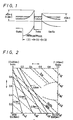
- Recently, enthusiastic research and development have been directed to an HET as an ultra-high speed element. An HET operable in a room temperature is disclosed in, for example, Applied Physics Letters Vol. 51, No. 13, pp 984 - 986, September 1987, which is constituted by disposing an emitter barrier layer 2 made of AℓSb0.92As0.08 and a collector barrier layer 3 made of GaAs at opposite sides of a base layer 1 made of InAs respectively so as to sandwich the base layer 1 therebetween, as shown in Fig. 1 which is a band model diagram of its conduction band in a biasing state.
- Since an offset gap ΔEB-C of a conduction band between the base and the collector of the HET thus constructed is 0.8 eV, it is required that an offset gap ΔEB-E of a conduction band of the emitter barrier layer between the base and the emitter is to be selected larger than the offset gap ΔEB-C. Accordingly, the offset gap ΔEB-E of 1.3 ev is established for the HET. However, with the gap ΔEB-E between the base and the emitter being such a high value of 1.3 ev, an energy of a hot electron injected from the emitter into the collector is too high to neglect the ionization in the collector due to the hot electron. More specifically, the hot electrons of high energy injected in the collector eject electrons from a valence band in the collector to generate an avalanche current, which degrades the saturation characteristics of the transistor. Hatched portions in Fig. 1 show an energy level where electrons exist.
- In the transistor constructed as described above, a layer adjacent to the base layer 1 of In-system, that is, the emitter barrier layer 2 is made of Aℓ-system, which causes a difficulty in setting a selection ratio of etching between the layers of the Aℓ-system and the In-system. Accordingly, upon leading a base electrode from the base layer 1 of the In-system which forms this kind of HET in actual practice, there arises a problem that an etching process for partially removing the In-system emitter barrier layer or emitter layer on the base layer 1 in order to partially expose the base layer 1 is extremely difficult.
- Accordingly it is an object of the present invention to provide an HET having an InAs base layer which is capable of improving the saturation characteristics and symplifying the fabrication process thereof.
- As an aspect of the present invention, a hot electron transistor is comprised of an InAs base layer, a GaSb emitter barrier layer deposited on one side of the InAs base layer, and a GaInAsSb collector barrier layer deposited on the other side of said InAs layer, whereby the InAs base layer is sandwiched between the GaSb emitter barrier layer and the GaInAsSb collector barrier layer the offset gap ΔEB-C of the conduction band between the base and the collector being selected more than 0.4 eV but less than 0.8 eV.
- The above, and other objects, features, and advantages of the present invention will become apparent from the following detailed description of illustrative embodiment thereof to be read in conjunction with the accompanying drawings, in which like reference numerals represent the same or similar parts.
-
- Fig. 1 is a diagram showing a band model of a conventional semiconducter device;
- Fig. 2 is a graph showing the relationship among the composition of GaxIn1-xSb1-y, the band gap and the lattice constant thereof;
- Fig. 3 is a cross-sectional view of an embodiment of a semiconductor device according to the present invention; and
- Fig. 4 is a band model diagram of the embodiment shown in Fig. 3.
- Before explaining a preferred embodiment of the present invention, reference will be made to the relationship between the band gap and the lattice constants of GaxIN1-xAsySb1-y which constitutes the principle of the present invention.
- Fig. 2 is a graph showing the relationship among the composition, the band gap and the lattice constant of GaxIn1-xAsySb1-y shown on page 41 of "HETERO-STRUCTURE LASERS", Part B, by H. C. Casey, and Jr M. B. Panish, published by Academic Press. As is apparent from the graph, the GaInAsSb-system semiconductor has a band gap smaller than 0.8 eV. It is therefore possible to provide an offset gap ΔEB-C of the conduction band between the base and the collector sufficiently smaller than 0.8 ev, and accordingly it is possible to provide an offset gap ΔEB-E of the conduction band between the base and the emitter smaller than the conventional value of 1.3 eV, for example, 0.8 ev, by an emitter barrier layer made of GaSb.
- Now, an embodiment of a hot electron transistor (HET) according to the present invention will be explained with reference to Figs. 3 and 4.
- As shown in Fig. 3, on an n-type highly concentrated
GaSb semiconductor substrate 9, there are sequentially formed an n-typeGaSb collector layer 10 having a thickness of 200 nm, an intrinsicGaSb underlaying layer 13A having a thickness of 100 nm for a collector barrier layer, an intrinsic GaxIn1-xAsySb1-y, for example, Ga0.8In0.2As0.2Sb0.8collector barrier layer 13 having a thickness of 10 nm, an n-typeInAs base layer 11 having a thickness of 10 nm, an intrinsic GaAsemitter barrier layer 12 having a thickness of 100 nm, and an n-type highly concentrationGaSb emitter layer 14 having a thickness of 200 nm. Thereafter, theemitter layer 14 and theemitter barrier layer 12 are partially etched away by an etching method which has selectively in stching Ga-system and In-system materials, for example, a reactive ion etching (RIE) method using a CCl₂F₂+He system to thereby partially expose a part of thebase layer 11. Abase electrode 15 is made in ohmic contact with the exposed surface of thebase layer 11, and simultaneously anemitter electrode 16 is deposited on theemitter layer 14 in an ohmic contact therewith. Further, acollector electrode 17 is ohmicly deposited, for example, on the rear surface of thesubstrate 9. - According to the invention, the offset gap ΔEB-E of the conduction band between the base and the emitter becomes 0.8 ev, while the offset gap ΔEB-C between the base and the collector falls in a range of more than 0.4 - and less than 0.8 eV, thereby making it possible for this device to operate as a transistor at room temperature.
- Incidentally, when atomic ratios x and y of the
collector barrier layer 13 composed of GaxIn1-xAsySb1-y are set in ranges of 0.8 ≦ x < 1.0 and 0 < y ≦ 0.2, respectively, the lattice constants thereof match or favorably match with the lattice constants of InAs constituting thebase layer 11 to thereby make it possible to perform a good epitaxy. Further, it is possible to perform a good epitaxy of the GaSbemitter barrier layer 12 on thisInAs base layer 11. Further, the offset gap ΔEB-C between the base and the collector can be fallen within a range of 0.4 eV - 0.8 eV while the offset gap ΔEB-E between the base and the emitter can be determined as 0.8 eV. - The respective layers 10-13A-13-11-12-14 can be formed continuously and epitaxially as a series of works by the MOCVD (Metal Organic Chemical Vapor Deposition) method, MBE (molecular Beam Epitaxy) method and so on.
-
Reference numerals - While
GaSb substrate 9 is used in the embodiment shown in Fig. 3, in some cases GaSb or InAs substrate of, for example, n-type having a high impurity concentration, i.e. low resistivity may be provided, and thereon the GaSbcollector layer 10 may be epitaxially grown. Also in this case, the respective layers on thesubstrate 9 can be epitaxially grown successively by a series of works by the MOCVD method or the MBE method. - According to the construction of the present invention having the band model shown in Fig. 4, when the
collector barrier layer 13 is made of a compound semiconductor of GaInAsSb-system, the offset gap ΔEB-C of the conduction band between the base and the collector can be made smaller than 0.8 eV. Further, when theemitter barrier layer 12 is made of GaSb, the offset gap ΔEB-E of the conduction band between the base and the emitter of theemitter barrier layer 12 can be made such a relatively small value of 0.8 eV. Thus, it becomes possible to avoid such phenomena that hot electrons of unnecessarily high energy are introduced into the collector and that an avalanche current is generated, thereby making it possible to improve the saturation characteristics of the device. - Further, the selective etching for the
emitter layer 14 and theemitter barrier layer 12 in order to partially expose thebase layer 11 is performed by using the CCl₂F₂+He-system etching gas which has different etching speeds between the Ga-system material and In-system material, so that one portion of thebase layer 11 can be exposed outside easily.
Claims (5)
- A hot electron transistor comprising:
an InAs base layer (11);
a GaSb emitter barrier layer (12) deposited on one side of said InAs base layer (11); and
a collector barrier layer (13) deposited on the other side of said InAs base layer (11), whereby said InAs base layer (11) is sandwiched between said GaSb emitter barrier layer (12) and said collector barrier layer (13),
characterized in that
said collector barrier layer (13) is formed from GaInAsSb, the offset gap Δ EB-C of the conduction band between the base and the collector being selected more than 0.4 eV but less than 0.8 eV. - A hot electron transistor according to claim 1 further comprising a GaSb substrate (9, 10) on which said collector barrier layer (13), said base layer (11) and said emitter barrier layer (12) are epitaxially deposited in sequence.
- A semiconductor device according to anyone of claims 1 to 2, wherein said base layer (11) is of an n-type conductivity, said emitter barrier layer (12) is of an i-type conductivity and said collector barrier layer (13) is of an i-type conductivity, respectively.
- A method for manufacturing a hot electron transistor according to claims 1 to 3, wherein said base layer (11), said emitter barrier layer (12) and said collector barrier layer (13) are formed by a metal organic chemical vapor deposition method.
- A method for manufacturing a hot electron transistor according to claims 1 to 3, wherein said base layer (11), said emitter barrier layer (12) and said collector barrier layer (13) are formed by a molecular beam epitaxy method.
Applications Claiming Priority (2)
| Application Number | Priority Date | Filing Date | Title |
|---|---|---|---|
| JP18707/90 | 1990-01-29 | ||
| JP2018707A JP2527060B2 (en) | 1990-01-29 | 1990-01-29 | Semiconductor device |
Publications (2)
| Publication Number | Publication Date |
|---|---|
| EP0440139A1 EP0440139A1 (en) | 1991-08-07 |
| EP0440139B1 true EP0440139B1 (en) | 1994-12-14 |
Family
ID=11979123
Family Applications (1)
| Application Number | Title | Priority Date | Filing Date |
|---|---|---|---|
| EP91101080A Expired - Lifetime EP0440139B1 (en) | 1990-01-29 | 1991-01-28 | Hot electron transistor |
Country Status (4)
| Country | Link |
|---|---|
| US (1) | US5124771A (en) |
| EP (1) | EP0440139B1 (en) |
| JP (1) | JP2527060B2 (en) |
| DE (1) | DE69105762T2 (en) |
Families Citing this family (8)
| Publication number | Priority date | Publication date | Assignee | Title |
|---|---|---|---|---|
| US5326985A (en) * | 1992-09-28 | 1994-07-05 | Motorola, Inc. | Bipolar doped semiconductor structure and method for making |
| US5298763A (en) * | 1992-11-02 | 1994-03-29 | Motorola, Inc. | Intrinsically doped semiconductor structure and method for making |
| US5436469A (en) * | 1994-06-15 | 1995-07-25 | Moll; Nicolas J. | Band minima transistor |
| KR0170474B1 (en) * | 1995-12-21 | 1999-02-01 | 정선종 | Resonant Tunneling Hot Electronics |
| JP3388090B2 (en) * | 1996-04-26 | 2003-03-17 | 富士通株式会社 | Current driven semiconductor device and high mobility transistor |
| KR19980034078A (en) * | 1996-11-05 | 1998-08-05 | 양승택 | Hot Electron Device and Resonant Tunneling Hot Electronic Device |
| EP1719188A4 (en) * | 2004-01-22 | 2009-02-25 | Advanced Optical Materials Llc | PHOTOTRANSISTORS, METHODS OF MAKING PHOTOTRANSISTORS AND METHODS OF DETECTING LIGHT |
| US7639459B2 (en) * | 2005-01-10 | 2009-12-29 | Hitachi Global Storage Technologies Netherlands B.V. | Three terminal magnetic sensor having an in-stack longitudinal biasing layer structure |
Citations (1)
| Publication number | Priority date | Publication date | Assignee | Title |
|---|---|---|---|---|
| EP0159273A2 (en) * | 1984-04-17 | 1985-10-23 | Fujitsu Limited | Semiconductor device |
Family Cites Families (2)
| Publication number | Priority date | Publication date | Assignee | Title |
|---|---|---|---|---|
| JPS63229752A (en) * | 1987-03-19 | 1988-09-26 | Fujitsu Ltd | Very high speed semiconductor device |
| US4829343A (en) * | 1987-07-17 | 1989-05-09 | American Telephone & Telegraph Company, At&T Bell Laboratories | Hot electron transistor |
-
1990
- 1990-01-29 JP JP2018707A patent/JP2527060B2/en not_active Expired - Fee Related
-
1991
- 1991-01-28 EP EP91101080A patent/EP0440139B1/en not_active Expired - Lifetime
- 1991-01-28 DE DE69105762T patent/DE69105762T2/en not_active Expired - Fee Related
- 1991-01-29 US US07/647,411 patent/US5124771A/en not_active Expired - Fee Related
Patent Citations (1)
| Publication number | Priority date | Publication date | Assignee | Title |
|---|---|---|---|---|
| EP0159273A2 (en) * | 1984-04-17 | 1985-10-23 | Fujitsu Limited | Semiconductor device |
Also Published As
| Publication number | Publication date |
|---|---|
| DE69105762D1 (en) | 1995-01-26 |
| JPH03222478A (en) | 1991-10-01 |
| JP2527060B2 (en) | 1996-08-21 |
| US5124771A (en) | 1992-06-23 |
| EP0440139A1 (en) | 1991-08-07 |
| DE69105762T2 (en) | 1995-04-27 |
Similar Documents
| Publication | Publication Date | Title |
|---|---|---|
| Dumke et al. | GaAs GaAlAs heterojunction transistor for high frequency operation | |
| US5001534A (en) | Heterojunction bipolar transistor | |
| US4665412A (en) | Coupled heterostructure superlattice devices | |
| JP2801624B2 (en) | Heterojunction bipolar transistor | |
| EP0619613B1 (en) | A heterojunction bipolar transistor | |
| EP0507454B1 (en) | Semiconductor device comprising a heterojunction bipolar transistor and method of making the same | |
| EP0199435B1 (en) | Field effect semiconductor device | |
| US4751195A (en) | Method of manufacturing a heterojunction bipolar transistor | |
| JPH0750410A (en) | Semiconductor crystal laminated body, method for forming the same, and semiconductor device | |
| US20020190273A1 (en) | Bipolar transistor with upper heterojunction collector and method for making same | |
| EP0306258A2 (en) | Transistor | |
| JPH07118531B2 (en) | Hot electron unipolar transistor | |
| US5124771A (en) | Semiconductor device | |
| JPH077835B2 (en) | Hot electron transistor | |
| US5106766A (en) | Method of making a semiconductor device that comprises p-type III-V semiconductor material | |
| EP0566591A1 (en) | SEMICONDUCTOR DEVICE. | |
| US4929984A (en) | Resonant tunnelling barrier structure device | |
| US5206524A (en) | Heterostructure bipolar transistor | |
| EP0331482B1 (en) | Transistor structure | |
| US5912480A (en) | Heterojunction semiconductor device | |
| US5818073A (en) | Semiconductor device including doped spontaneously formed superlattice layer | |
| JP2687519B2 (en) | Semiconductor device and manufacturing method thereof | |
| EP0229672B1 (en) | A heterojunction bipolar transistor having a base region of germanium | |
| JPH032350B2 (en) | ||
| JPH0337735B2 (en) |
Legal Events
| Date | Code | Title | Description |
|---|---|---|---|
| PUAI | Public reference made under article 153(3) epc to a published international application that has entered the european phase |
Free format text: ORIGINAL CODE: 0009012 |
|
| AK | Designated contracting states |
Kind code of ref document: A1 Designated state(s): DE FR GB |
|
| 17P | Request for examination filed |
Effective date: 19920206 |
|
| 17Q | First examination report despatched |
Effective date: 19930510 |
|
| GRAA | (expected) grant |
Free format text: ORIGINAL CODE: 0009210 |
|
| AK | Designated contracting states |
Kind code of ref document: B1 Designated state(s): DE FR GB |
|
| REF | Corresponds to: |
Ref document number: 69105762 Country of ref document: DE Date of ref document: 19950126 |
|
| ET | Fr: translation filed | ||
| PLBE | No opposition filed within time limit |
Free format text: ORIGINAL CODE: 0009261 |
|
| STAA | Information on the status of an ep patent application or granted ep patent |
Free format text: STATUS: NO OPPOSITION FILED WITHIN TIME LIMIT |
|
| 26N | No opposition filed | ||
| REG | Reference to a national code |
Ref country code: GB Ref legal event code: IF02 |
|
| PGFP | Annual fee paid to national office [announced via postgrant information from national office to epo] |
Ref country code: FR Payment date: 20020110 Year of fee payment: 12 |
|
| PGFP | Annual fee paid to national office [announced via postgrant information from national office to epo] |
Ref country code: GB Payment date: 20020130 Year of fee payment: 12 |
|
| PGFP | Annual fee paid to national office [announced via postgrant information from national office to epo] |
Ref country code: DE Payment date: 20020227 Year of fee payment: 12 |
|
| PG25 | Lapsed in a contracting state [announced via postgrant information from national office to epo] |
Ref country code: GB Free format text: LAPSE BECAUSE OF NON-PAYMENT OF DUE FEES Effective date: 20030128 |
|
| PG25 | Lapsed in a contracting state [announced via postgrant information from national office to epo] |
Ref country code: DE Free format text: LAPSE BECAUSE OF NON-PAYMENT OF DUE FEES Effective date: 20030801 |
|
| GBPC | Gb: european patent ceased through non-payment of renewal fee | ||
| PG25 | Lapsed in a contracting state [announced via postgrant information from national office to epo] |
Ref country code: FR Free format text: LAPSE BECAUSE OF NON-PAYMENT OF DUE FEES Effective date: 20030930 |
|
| REG | Reference to a national code |
Ref country code: FR Ref legal event code: ST |