EP0440155B1 - Sonde für Strömungsgeschwindigkeit - Google Patents
Sonde für Strömungsgeschwindigkeit Download PDFInfo
- Publication number
- EP0440155B1 EP0440155B1 EP91101125A EP91101125A EP0440155B1 EP 0440155 B1 EP0440155 B1 EP 0440155B1 EP 91101125 A EP91101125 A EP 91101125A EP 91101125 A EP91101125 A EP 91101125A EP 0440155 B1 EP0440155 B1 EP 0440155B1
- Authority
- EP
- European Patent Office
- Prior art keywords
- flow
- velocity sensor
- sensor probe
- thermally conductive
- thermistor
- Prior art date
- Legal status (The legal status is an assumption and is not a legal conclusion. Google has not performed a legal analysis and makes no representation as to the accuracy of the status listed.)
- Expired - Lifetime
Links
- 239000000523 sample Substances 0.000 title claims description 50
- 239000002184 metal Substances 0.000 claims description 14
- 229910052751 metal Inorganic materials 0.000 claims description 14
- 239000012530 fluid Substances 0.000 claims description 8
- 230000001419 dependent effect Effects 0.000 claims description 5
- 229920005989 resin Polymers 0.000 claims description 4
- 239000011347 resin Substances 0.000 claims description 4
- 239000010931 gold Substances 0.000 claims description 3
- PZNSFCLAULLKQX-UHFFFAOYSA-N Boron nitride Chemical compound N#B PZNSFCLAULLKQX-UHFFFAOYSA-N 0.000 claims description 2
- PCHJSUWPFVWCPO-UHFFFAOYSA-N gold Chemical compound [Au] PCHJSUWPFVWCPO-UHFFFAOYSA-N 0.000 claims description 2
- 229910052737 gold Inorganic materials 0.000 claims description 2
- 239000004020 conductor Substances 0.000 claims 2
- 229910052582 BN Inorganic materials 0.000 claims 1
- 229910052581 Si3N4 Inorganic materials 0.000 claims 1
- PNEYBMLMFCGWSK-UHFFFAOYSA-N aluminium oxide Inorganic materials [O-2].[O-2].[O-2].[Al+3].[Al+3] PNEYBMLMFCGWSK-UHFFFAOYSA-N 0.000 claims 1
- 229910003460 diamond Inorganic materials 0.000 claims 1
- 239000010432 diamond Substances 0.000 claims 1
- 230000001747 exhibiting effect Effects 0.000 claims 1
- HQVNEWCFYHHQES-UHFFFAOYSA-N silicon nitride Chemical compound N12[Si]34N5[Si]62N3[Si]51N64 HQVNEWCFYHHQES-UHFFFAOYSA-N 0.000 claims 1
- 230000000747 cardiac effect Effects 0.000 description 30
- 239000008280 blood Substances 0.000 description 19
- 210000004369 blood Anatomy 0.000 description 19
- 238000005259 measurement Methods 0.000 description 15
- 238000000034 method Methods 0.000 description 12
- 238000010586 diagram Methods 0.000 description 9
- 229910001120 nichrome Inorganic materials 0.000 description 9
- 230000035945 sensitivity Effects 0.000 description 7
- FAPWRFPIFSIZLT-UHFFFAOYSA-M Sodium chloride Chemical compound [Na+].[Cl-] FAPWRFPIFSIZLT-UHFFFAOYSA-M 0.000 description 6
- YURDCJXYOLERLO-LCYFTJDESA-N (2E)-5-methyl-2-phenylhex-2-enal Chemical compound CC(C)C\C=C(\C=O)C1=CC=CC=C1 YURDCJXYOLERLO-LCYFTJDESA-N 0.000 description 5
- 239000012528 membrane Substances 0.000 description 5
- 210000001147 pulmonary artery Anatomy 0.000 description 5
- 230000017531 blood circulation Effects 0.000 description 4
- 239000007767 bonding agent Substances 0.000 description 4
- 239000003822 epoxy resin Substances 0.000 description 4
- 229920000647 polyepoxide Polymers 0.000 description 4
- 239000004593 Epoxy Substances 0.000 description 3
- 238000012937 correction Methods 0.000 description 3
- 230000014509 gene expression Effects 0.000 description 3
- 238000012544 monitoring process Methods 0.000 description 3
- 230000001105 regulatory effect Effects 0.000 description 3
- BZHJMEDXRYGGRV-UHFFFAOYSA-N Vinyl chloride Chemical compound ClC=C BZHJMEDXRYGGRV-UHFFFAOYSA-N 0.000 description 2
- 230000007423 decrease Effects 0.000 description 2
- 238000010438 heat treatment Methods 0.000 description 2
- 239000003978 infusion fluid Substances 0.000 description 2
- 239000007924 injection Substances 0.000 description 2
- 238000002347 injection Methods 0.000 description 2
- 238000012545 processing Methods 0.000 description 2
- 238000012546 transfer Methods 0.000 description 2
- 208000028399 Critical Illness Diseases 0.000 description 1
- 206010019280 Heart failures Diseases 0.000 description 1
- 239000004642 Polyimide Substances 0.000 description 1
- NIXOWILDQLNWCW-UHFFFAOYSA-N acrylic acid group Chemical group C(C=C)(=O)O NIXOWILDQLNWCW-UHFFFAOYSA-N 0.000 description 1
- 230000001070 adhesive effect Effects 0.000 description 1
- 239000011324 bead Substances 0.000 description 1
- 230000005540 biological transmission Effects 0.000 description 1
- 210000004204 blood vessel Anatomy 0.000 description 1
- 230000036760 body temperature Effects 0.000 description 1
- 238000001816 cooling Methods 0.000 description 1
- 238000009792 diffusion process Methods 0.000 description 1
- 238000010790 dilution Methods 0.000 description 1
- 239000012895 dilution Substances 0.000 description 1
- 230000000694 effects Effects 0.000 description 1
- 230000002708 enhancing effect Effects 0.000 description 1
- 208000015181 infectious disease Diseases 0.000 description 1
- 239000000463 material Substances 0.000 description 1
- 229920001721 polyimide Polymers 0.000 description 1
- 239000004814 polyurethane Substances 0.000 description 1
- 229920002635 polyurethane Polymers 0.000 description 1
- 230000005855 radiation Effects 0.000 description 1
- 239000000243 solution Substances 0.000 description 1
- 238000001356 surgical procedure Methods 0.000 description 1
- 238000002604 ultrasonography Methods 0.000 description 1
Images


Classifications
-
- A—HUMAN NECESSITIES
- A61—MEDICAL OR VETERINARY SCIENCE; HYGIENE
- A61B—DIAGNOSIS; SURGERY; IDENTIFICATION
- A61B5/00—Measuring for diagnostic purposes; Identification of persons
- A61B5/02—Detecting, measuring or recording for evaluating the cardiovascular system, e.g. pulse, heart rate, blood pressure or blood flow
- A61B5/026—Measuring blood flow
- A61B5/0275—Measuring blood flow using tracers, e.g. dye dilution
- A61B5/028—Measuring blood flow using tracers, e.g. dye dilution by thermo-dilution
-
- G—PHYSICS
- G01—MEASURING; TESTING
- G01F—MEASURING VOLUME, VOLUME FLOW, MASS FLOW OR LIQUID LEVEL; METERING BY VOLUME
- G01F1/00—Measuring the volume flow or mass flow of fluid or fluent solid material wherein the fluid passes through a meter in a continuous flow
- G01F1/68—Measuring the volume flow or mass flow of fluid or fluent solid material wherein the fluid passes through a meter in a continuous flow by using thermal effects
- G01F1/684—Structural arrangements; Mounting of elements, e.g. in relation to fluid flow
- G01F1/688—Structural arrangements; Mounting of elements, e.g. in relation to fluid flow using a particular type of heating, cooling or sensing element
- G01F1/69—Structural arrangements; Mounting of elements, e.g. in relation to fluid flow using a particular type of heating, cooling or sensing element of resistive type
Definitions
- This invention relates to a flow-velocity sensor probe used in flow-velocity measurement such as measurement of cardiac output.
- thermodilution method based upon the right-heart catheter method, in which a catheter is held in the pulmonary artery.
- thermodilution method the information obtained through the thermodilution method is discontinuous.
- an infusion fluid when cardiac output is measured, an infusion fluid must be injected each time a measurement is taken. Owing to such problems as the complexity of surgery, infection which accompanies the repeated injection of a cold saline solution, a drop in the body temperature and increased load on the heart, the number of times measurements can be taken is limited, especially in case of a seriously ill patient whose cardiac output needs to be ascertained.
- One method of continuously measuring cardiac output very precisely is a method using the CCOM system (continuous cardiac output monitoring system) developed by the present inventors (US-A-4,685,470).
- This monitoring system includes a catheter probe and a monitoring unit.
- CFT thermistor
- a thermistor is used as an ordinary temperature sensor and operates on the basis of a change in the resistance value in dependence upon a change in temperature.
- thermistor Since a thermistor is also a resistor, the thermistor itself emits heat when a large amount of current is passed through it. Accordingly, when such a thermistor is placed in the bloodstream, the temperature of the thermistor becomes that at which equilibrium is established between the amount of heat produced by the electric current and the amount of heat carried away by the flow of blood. Since this equilibrium temperature Tt varies in dependence upon the flow velocity, the thermistor can be utilized as a flow-velocity sensor.
- thermodilution method the above-mentioned calibration is performed by the thermodilution method, and two thermistors are attached to a catheter probe.
- One of these thermistors is a self-heating CFT thermistor for measuring equilibrium temperature and a PAT thermistor for measuring blood temperature using the thermodilution method.
- Tt R Tt R - K ⁇ (TB - TB CAL )
- cardiac output CO can be calculated in accordance with Eq. (8) from the continuously measured CFT thermistor temperature Tt R and blood temperature TB.
- the full range (0 - 12 L/min) of cardiac output is calculated with the value of the constant A in Eq. (8) being a simple value, there is a decline in precision. Therefore, the range over which cardiac output is measured is divided into two parts. Specifically, cardiac output is calculated using arithmetic expressions for a case where the value of A is AH when the cardiac output is in a high flow-rate region and for a case where the value of A is AL when the cardiac output is in a low flow-rate region.
- the constant A is an index of temperature with regard to flow velocity and shall be referred to as the "A value" hereinafter.
- the calibration of cardiac output is carried out by the thermodilution method.
- cardiac output is obtained in accordance with the following arithmetic expressions where the measurement range is divided into two parts:
- cardiac output is obtained in accordance with the following arithmetic expressions where the measurement range is divided into two parts:
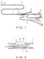
- Fig. 1 illustrates the structure of a conventional flow-velocity sensor probe (catheter probe).
- the probe includes a catheter tube 1 and a balloon inflating line 9, a pressure measuring line 10, an infusion fluid injecting line 11 and a thermistor connecting line 12, all of which are connected to the catheter tube 1 via a manifold 6.
- the structure of the catheter tube 1 is such that a pressure measuring aperture 4, a CFT thermistor 2 and PAT thermistor 3 are disposed at the tip of the catheter tube.
- the CFT thermistor 2 and PAT thermistor 3 are electrically connected to a CFT connector 7 and a PAT connector 8, respectively.
- Fig. 2 illustrates the structure of the CFT thermistor mounting in the conventional flow-velocity sensor probe.
- the CFT thermistor 2 is dipped in a waterproof epoxy resin 34 in order to assure a waterproof condition and it is then inserted into a tube 31 made of polyimide.
- the CFT thermistor 2 inserted into the tube 31 is fitted into a side aperture 29 in the catheter tube 1, and the thermistor 2 is then bonded into place by an epoxy bonding agent 36 in order to fix the thermistor to the catheter tube 1.
- Thermistor leads 32 are passed through the interior of the catheter tube 1 and are electrically connected to the CFT connector 7 or the thermistor connecting line 12.
- the conventional flow-velocity probe (catheter probe) allows escape of heat along the thermistor leads, and this has an effect upon the temperature of the PAT thermistor.
- US-A-3 435 400 discloses a flow-velocity sensor probe having a metallic membrane used as a resistance heater, i.e. heat generating means.
- the temperature sensor (thermistor bead) is provided for detecting the temperature of the membrane which is disposed in highly efficient heat-transfer relationship with the medium to be measured.
- the heat generating means and the heat radiating means are both represented by the same membrane and thus are identical.
- the metallic membrane of the sensor probe acts both as heat generating means and as heat radiating means and current flows through the membrane itself.
- an object of the present invention is to provide a flow-velocity sensor probe which solves the aforementioned problems encountered in the prior art.
- a flow-velocity sensor probe comprising heat generating means being not in direct contact with the fluid temperature detecting means for detecting the temperature produced by the heat generating means, the temperature being dependent on the flow velocity, and thermally conductive heat radiating means placed in the fluid to be measured.
- the thermally conductive heat radiating means comprises a metal arranged to be in contact with the fluid. It is provided as a separate part in close proximity to and in thermally conductive contact with the heat generating means.
- Fig. 3 is a diagram showing a flow-velocity sensor probe according to an embodiment of the present invention and illustrating the structure of a CFT thermistor mounting portion in the side aperture of a catheter.
- the CFT thermistor 2 is dipped in the waterproof epoxy resin 34 in order to assure a waterproof condition and it is then bonded to a small metal piece 35.
- the small metal piece 35 consists of gold (Au), which has a high thermal conductivity.
- Boron nitride (BN) is mixed with the waterproof epoxy resin 34 for the purpose of enhancing its thermal conductivity.
- the CFT thermistor 2 affixed to the small metal piece 35 is bonded into place by the epoxy bonding agent 36 in order to fix the thermistor in the side aperture 29 to the catheter tube 1.
- the thermistor and the catheter tube are bonded by an epoxy bonding agent 33, which exhibits an excellent adhesive property.
- a material having an excellent thermal conductivity is selected and used as the waterproof epoxy resin 34.
- the thermistor leads 32 are electrically connected to the CFT connector 7 of the thermistor connecting line 12 through the interior of the catheter probe 1. Passing an electric current via the thermistor leads 32 causes the thermistor 2 to produce heat, which is transmitted to the outside via the resin 34 and the metal piece 35.
- the sensitivity of the flow-velocity sensor probe to flow velocity can be expressed using the above-mentioned A value as an index.
- Fig. 4 illustrates the relationship between the A value and a change in the CFT thermistor temperature plotted against the flow velocity calculated from Eq. (2).
- the CFT temperature decreases, and therefore the sensitivity of the flow-velocity probe is improved, with an increase in the A value.
- the A values shown in Fig. 4 are values obtained by multiplying the A value in Eq. (2) by -1000.
- Fig. 5 is a block diagram showing a system for measuring the A value of the flow-velocity sensor probe.
- the system is constituted by an acrylic tube having a diameter of 20 mm and a tube made of vinyl chloride.
- a saline solution 20 is circulated through this tubing instead of blood.
- the arrows in Fig. 5 indicate the direction in which the saline solution 20 circulates.
- the saline solution 20 is heated to a temperature of 37°C in an isothermal bath 19, and the solution is regulated to expredetermined flow rate by a diffusion pump 23 and a flow-rate regulating valve 22.
- the circulating flow rate is measured continuously by an electromagnetic blood flowwmeter 17.
- the value measured by the electromagnetic blood flowmeter 17 is calibrated in advance by comparison with a value obtained using a method of measuring the flow rate through a graduated measuring cylinder.
- the agitator 21 agitates the cold saline solution when calibration in the thermodilution method is carried out, and it serves as a substitute for the heart in a living body.
- the CFT thermistor 18 is monitored by a CCOM monitor 24, and the electromagnetic blood flowmeter 17 and CCOM monitor 24 are connected to a computer 25.
- the flow-rate regulating valve 22 is manipulated to reduce the circulating flow rate of the circulating circuit 14 stepwise from 12 L/min.
- the CFT temperature and the PAT temperature blood temperature are then measured upon each stepwise reduction in flow rate, and the A value is found from a correlation between these temperatures and the flow velocity calculated from the flow rate indicated by the electromagnetic blood flowmeter 17.
- Fig. 6 shows the results of measuring and compares the performance of the flow-velocity sensor probe of the present invention and the performance of the conventional probe.
- the flow-velocity sensor of the present invention has an A value greater than five times that of the conventional flow-velocity sensor probe in both the high and the low flow-rate regions.
- the B parameter of the probe according to the present invention is lower by about three points. The number of probes used in measurement, and the A values and the values of the B parameters were average values for the number of probes used in measurement.
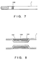
- Fig. 7 is a diagram illustrating another embodiment and showing the flow-velocity sensor of the invention fitted into a catheter
- Fig. 8 is an enlarged view showing the structure of this flow-velocity sensor.
- a flow-velocity sensor 100 As shown in Fig. 7, a flow-velocity sensor 100 according to this embodiment is fitted into a catheter tube 1.
- a nichrome wire 102 is used as the heat generating means in this embodiment and it is wound upon the catheter tube 1 from several tens of times to several hundred times.
- a thermistor 103 for detecting temperature is disposed so as to contact the nichrome wire 102 as much as possible and to be surrounded by the nichrome wire 102.
- the outer side of the nichrome wire 102 wound upon the catheter tube 1 is covered by a metal ring 104, and the nichrome wire 102 and metal ring 104 used as a means of radiating thermally conductive heat, are contacted and fixed by a waterproof bonding agent.
- the outer diameter of the catheter tube is reduced beforehand by the thickness of the nichrome wire and of the metal ring.
- the nichrome wire used here has a diameter of 0.05 mm and a resistance value of 560.7 ⁇ /m.
- the wire is sheathed in polyurethane in order to insulate it electrically.
- Passing an electric current through the nichrome wire causes the wire to produce heat, which is transmitted to the outside via the metal ring.
- the extent of transmission depends upon the flow velocity of the exterior fluid. The flow velocity can be measured by measuring the temperature of the nichrome wire at such time.
Landscapes
- Health & Medical Sciences (AREA)
- Life Sciences & Earth Sciences (AREA)
- Physics & Mathematics (AREA)
- Fluid Mechanics (AREA)
- General Physics & Mathematics (AREA)
- Engineering & Computer Science (AREA)
- Molecular Biology (AREA)
- Cardiology (AREA)
- Biophysics (AREA)
- Pathology (AREA)
- Hematology (AREA)
- Biomedical Technology (AREA)
- Heart & Thoracic Surgery (AREA)
- Medical Informatics (AREA)
- Physiology (AREA)
- Surgery (AREA)
- Animal Behavior & Ethology (AREA)
- General Health & Medical Sciences (AREA)
- Public Health (AREA)
- Veterinary Medicine (AREA)
- Measuring Pulse, Heart Rate, Blood Pressure Or Blood Flow (AREA)
- Measuring Volume Flow (AREA)
Claims (9)
- Meßfühlersonde für Strömungsgeschwindigkeit umfassend- ein Wärmeerzeugungsmittel (2, 102),- ein wärmeleitendes Wärmestrahlungsmittel (35, 104),- ein Temperaturerfassungsmittel (2, 103), das die Temperatur des Wärmeerzeugungsmittels (2, 102) erfaßt, dessen Temperatur von der Strömungsgeschwindigkeit abhängig ist,dadurch gekennzeichnet daß,- das wärmeleitende Wärmestrahlungsmittel (35, 104) ein Metall umfaßt, das in Kontakt mit dem Fluid angeordnet ist und als ein getrenntes Teil in dichter Nähe zu und in wärmeleitendem Kontakt mit dem Wärmeerzeugungsmittel (2, 102) vorgesehen ist, um zu verhindern, daß das Wärmeerzeugungsmittel (2, 102) in direktem Kontakt mit dem zu messenden Fluid steht.
- Meßfühlersonde für Strömungsgeschwindigkeit nach Anspruch 1, bei der das wärmeleitende Wärmestrahlungsmittel (104) das Wärmeerzeugungsmittel (102) überdeckt.
- Meßfühlersonde für Strömungsgeschwindigkeit nach Anspruch 1 oder 2, bei der das wärmeleitende Wärmestrahlungsmittel weiter eine Harzschicht (34) umfaßt, die eine Wasserdichtigkeitseigenschaft und eine Eigenschaft elektrischer Isolierung aufweist, die so angeordnet ist, daß sie in Kontakt mit dem Wärmeerzeugungsmittel (2) ist.
- Meßfühlersonde für Strömungsgeschwindigkeit nach Anspruch 3, bei der ein eine hohe Wärmeleitfähigkeit und einen hohen Durchgangswiderstand aufweisendes wärmeleitendes Material in die Harzschicht (34) gemischt ist.
- Meßfühlersonde für Strömungsgeschwindigkeit nach Anspruch 4, bei der das wärmeleitende Material wenigstens ein Element umfaßt, das aus der aus Bornitrid, Siliciumnitrid, Aluminiumoxid und Diamant bestehenden Gruppe ausgewählt ist.
- Meßfühlersonde für Strömungsgeschwindigkeit nach einem der Ansprüche 1 bis 5, bei der das Metall des wärmeleitenden Wärmestrahlungsmittels (35, 104) Gold ist.
- Meßfühlersonde für Strömungsgeschwindigkeit nach einem der Ansprüche 1 bis 6, bei der das wärmeleitende Wärmestrahlungsmittel einen Metallring (104) umfaßt, um die durch das Wärmeerzeugungsmittel (102) erzeugte Wärme auf das Fluid zu übertragen.
- Meßfühlersonde für Strömungsgeschwindigkeit nach einem der Ansprüche 1 bis 7, bei der das Wärmeerzeugungsmittel (2, 102) und das Temperaturerfassungsmittel (103) einen einzelnen Widerstand umfassen.
- Meßfühlersonde für Strömungsgeschwindigkeit nach einem der Ansprüche 1 bis 8, bei der das Temperaturerfassungsmittel (103) derart vorgesehen ist, daß es durch das Wärmeerzeugungsmittel (102) umgeben ist.
Applications Claiming Priority (2)
| Application Number | Priority Date | Filing Date | Title |
|---|---|---|---|
| JP2016098A JP2866132B2 (ja) | 1990-01-29 | 1990-01-29 | 流速センサプローブ |
| JP16098/90 | 1990-01-29 |
Publications (3)
| Publication Number | Publication Date |
|---|---|
| EP0440155A2 EP0440155A2 (de) | 1991-08-07 |
| EP0440155A3 EP0440155A3 (en) | 1991-09-11 |
| EP0440155B1 true EP0440155B1 (de) | 1996-09-11 |
Family
ID=11907041
Family Applications (1)
| Application Number | Title | Priority Date | Filing Date |
|---|---|---|---|
| EP91101125A Expired - Lifetime EP0440155B1 (de) | 1990-01-29 | 1991-01-29 | Sonde für Strömungsgeschwindigkeit |
Country Status (5)
| Country | Link |
|---|---|
| US (1) | US5373850A (de) |
| EP (1) | EP0440155B1 (de) |
| JP (1) | JP2866132B2 (de) |
| AU (1) | AU639065B2 (de) |
| DE (1) | DE69121924T2 (de) |
Families Citing this family (20)
| Publication number | Priority date | Publication date | Assignee | Title |
|---|---|---|---|---|
| US6387052B1 (en) * | 1991-01-29 | 2002-05-14 | Edwards Lifesciences Corporation | Thermodilution catheter having a safe, flexible heating element |
| US5553622A (en) * | 1991-01-29 | 1996-09-10 | Mckown; Russell C. | System and method for controlling the temperature of a catheter-mounted heater |
| US5617870A (en) * | 1993-04-29 | 1997-04-08 | Scimed Life Systems, Inc. | Intravascular flow measurement system |
| US5509424A (en) * | 1994-01-28 | 1996-04-23 | Aws Salim Nashef | Continuous cardiac output monitoring system |
| US5525040A (en) * | 1994-03-31 | 1996-06-11 | B&B Financial Planning Inc. | Controller for oil wells with a thermal dispersion probe |
| JP3696682B2 (ja) * | 1996-02-09 | 2005-09-21 | テルモ株式会社 | 流速測定用センサプローブ |
| WO1998014114A1 (en) * | 1996-10-02 | 1998-04-09 | Baxter International Inc. | Reduced-noise catheter |
| US6343223B1 (en) * | 1997-07-30 | 2002-01-29 | Mallinckrodt Inc. | Oximeter sensor with offset emitters and detector and heating device |
| US6431010B1 (en) | 1998-03-09 | 2002-08-13 | Michael A. Joffe | Optical fiber-based fluid flow anemometer |
| US6251107B1 (en) * | 1998-06-25 | 2001-06-26 | Cardima, Inc. | Ep catheter |
| US6986744B1 (en) | 1999-02-02 | 2006-01-17 | Transonic Systems, Inc. | Method and apparatus for determining blood flow during a vascular corrective procedure |
| DE29907566U1 (de) * | 1999-04-28 | 1999-08-26 | Honsberg & Co. KG, 42897 Remscheid | Strömungssensor |
| US6383144B1 (en) | 2000-01-18 | 2002-05-07 | Edwards Lifesciences Corporation | Devices and methods for measuring temperature of a patient |
| US6746408B2 (en) | 2001-05-29 | 2004-06-08 | Transonic Systems Inc. | Method of blood flow measurement in arterio-venous hemodialysis shunts by indicator dilution |
| GB0425186D0 (en) * | 2004-11-15 | 2004-12-15 | Univ Cambridge Tech | In-situ calibration verification device and method for electromagnetic flowmeters |
| US9557344B2 (en) | 2011-07-12 | 2017-01-31 | The Hong Kong Polytechnic University | Sensor for measuring flow speed of a fluid |
| EP2771652A4 (de) * | 2011-10-28 | 2015-06-03 | The Feinstein Inst Medical Res | Mikrochipsensor zur kontinuierlichen überwachung des regionalen blutflusses |
| JP6618254B2 (ja) * | 2014-12-24 | 2019-12-11 | 日本ライフライン株式会社 | 温度測定装置およびカテーテルシステム |
| EP3243432B1 (de) * | 2015-01-05 | 2022-10-12 | Nipro Corporation | Blutdurchflussmesser und messvorrichtung |
| US11564584B2 (en) * | 2016-09-28 | 2023-01-31 | Koninklijke Philips N.V. | System for determining blood flow |
Family Cites Families (31)
| Publication number | Priority date | Publication date | Assignee | Title |
|---|---|---|---|---|
| US3075515A (en) * | 1958-10-17 | 1963-01-29 | Albert M Richards | Blood flow meter |
| US3435400A (en) * | 1966-01-26 | 1969-03-25 | Paul Beckman | Thermal probe |
| DE1573240A1 (de) * | 1966-07-05 | 1970-11-26 | Rudolf Koch | Thermosonde zum Messen der Herzbluttemperatur |
| US3438253A (en) * | 1966-11-15 | 1969-04-15 | Frederick W Kuether | Thermal device for measuring direction and velocity of fluid flow |
| US3595079A (en) * | 1967-11-13 | 1971-07-27 | Univ Northwestern | Fluid flow velocity measuring apparatus |
| US3678922A (en) * | 1971-01-14 | 1972-07-25 | Univ Temple | Dilution method and apparatus for measurement of fluid flow rate |
| US3789831A (en) * | 1972-02-11 | 1974-02-05 | D Kopaniky | Thermoelectric probe apparatus for tissue fluid flow measurement |
| US3820530A (en) * | 1973-02-16 | 1974-06-28 | Gifford Instr Labor Inc | Cardiac output measuring method and apparatus |
| US3933149A (en) * | 1974-04-18 | 1976-01-20 | Salera Edmond A | Anisothermal differentiator |
| DD118524A5 (de) * | 1974-05-24 | 1976-03-12 | ||
| FR2291731A1 (fr) * | 1974-11-20 | 1976-06-18 | Obermajer Wladimir | Procede et dispositif de mesure de la capacite cardiaque |
| US3995623A (en) * | 1974-12-23 | 1976-12-07 | American Hospital Supply Corporation | Multipurpose flow-directed catheter |
| US4240441A (en) * | 1978-10-10 | 1980-12-23 | The United States Of America As Represented By The Secretary Of The Navy | Carotid thermodilution catheter |
| US4230126A (en) * | 1978-11-20 | 1980-10-28 | Elings Virgil B | Apparatus and method for measuring extravascular lung water |
| US4354504A (en) * | 1979-09-04 | 1982-10-19 | Bro William J | Thermal diffusion flow probe |
| US4380237A (en) * | 1979-12-03 | 1983-04-19 | Massachusetts General Hospital | Apparatus for making cardiac output conductivity measurements |
| US4628743A (en) * | 1981-07-06 | 1986-12-16 | The Dow Chemical Company | Apparatus and method for metering sub-10 cc/minute liquid flow |
| DE3128107C2 (de) * | 1981-07-16 | 1983-07-21 | GMS, Gesellschaft für medizinische Sondentechnik mbH, 2300 Kiel | Impulsbeheizte thermoelektrische Strömungsmeßeinrichtung für lebendes Gewebe |
| US4572206A (en) * | 1982-04-21 | 1986-02-25 | Purdue Research Foundation | Method and apparatus for measuring cardiac output |
| US4502488A (en) * | 1983-01-13 | 1985-03-05 | Allied Corporation | Injection system |
| US4542748A (en) * | 1983-03-07 | 1985-09-24 | American Hospital Supply Corp. | Apparatus and method for measuring cardiac output |
| NL189547C (nl) * | 1983-04-12 | 1993-05-17 | Univ Erasmus | Stelsel voor het bepalen van de stroomsterkte van het hart van een patient. |
| US4621646A (en) * | 1983-12-15 | 1986-11-11 | The United States Of America As Represented By The Secretary Of The Army | Blood flow measuring method |
| US4632125A (en) * | 1984-01-13 | 1986-12-30 | American Hospital Supply Corp. | Right heart ejection fraction and cardiac output catheter |
| US4796640A (en) * | 1984-01-13 | 1989-01-10 | American Hospital Supply Corporation | Apparatus with fast response thermistor |
| JPS61125329A (ja) * | 1984-11-21 | 1986-06-13 | テルモ株式会社 | 心拍出量測定装置 |
| US4548516A (en) * | 1984-12-24 | 1985-10-22 | Helenowski Tomasz K | Sequential thermography fluid flow indicator |
| JPS62207435A (ja) * | 1986-03-07 | 1987-09-11 | テルモ株式会社 | 心拍出量測定用カテ−テル |
| US4901734A (en) * | 1987-08-17 | 1990-02-20 | Nova Medical Specialties | Dual-thermistor thermodilution catheter |
| US4960109A (en) * | 1988-06-21 | 1990-10-02 | Massachusetts Institute Of Technology | Multi-purpose temperature sensing probe for hyperthermia therapy |
| JPH02128753A (ja) * | 1988-11-09 | 1990-05-17 | Terumo Corp | 心拍出量測定装置 |
-
1990
- 1990-01-29 JP JP2016098A patent/JP2866132B2/ja not_active Expired - Fee Related
-
1991
- 1991-01-25 AU AU70036/91A patent/AU639065B2/en not_active Ceased
- 1991-01-29 EP EP91101125A patent/EP0440155B1/de not_active Expired - Lifetime
- 1991-01-29 DE DE69121924T patent/DE69121924T2/de not_active Expired - Fee Related
-
1992
- 1992-05-21 US US07/888,464 patent/US5373850A/en not_active Expired - Lifetime
Also Published As
| Publication number | Publication date |
|---|---|
| JP2866132B2 (ja) | 1999-03-08 |
| DE69121924T2 (de) | 1997-02-06 |
| EP0440155A3 (en) | 1991-09-11 |
| DE69121924D1 (de) | 1996-10-17 |
| AU639065B2 (en) | 1993-07-15 |
| EP0440155A2 (de) | 1991-08-07 |
| AU7003691A (en) | 1991-11-14 |
| US5373850A (en) | 1994-12-20 |
| JPH03221815A (ja) | 1991-09-30 |
Similar Documents
| Publication | Publication Date | Title |
|---|---|---|
| EP0440155B1 (de) | Sonde für Strömungsgeschwindigkeit | |
| US4941475A (en) | Thermodilution by heat exchange | |
| US5682899A (en) | Apparatus and method for continuous cardiac output monitoring | |
| US6387052B1 (en) | Thermodilution catheter having a safe, flexible heating element | |
| EP0278177B1 (de) | Verfahren und Gerät zur Messung des Sauerstoff-Partialdruckes und der Temperatur in lebendem Gewebe | |
| US6551250B2 (en) | Transit time thermodilution guidewire system for measuring coronary flow velocity | |
| CA1241580A (en) | Volumetric flow rate determination in conduits not directly accessible | |
| US6672172B2 (en) | Triggered flow measurement | |
| US4217910A (en) | Internal jugular and left ventricular thermodilution catheter | |
| US5788647A (en) | Method, system and apparatus for evaluating hemodynamic parameters | |
| US5078137A (en) | Apparatus for measuring oxygen partial pressure and temperature, in living tissue | |
| EP0182363B1 (de) | Vorrichtung zur Messung des Herzzeitvolumens | |
| Woodcock | Theory and practice of blood flow measurement | |
| US6394961B1 (en) | Method to increase transpulmonary thermodilution cardiac output accuracy by use of extravascular thermovolume to control the amount of thermal indicator | |
| US5056526A (en) | Device for global evaluation of the left ventricular ejection fraction by thermodilution | |
| EP0226220A2 (de) | Bestimmung des Herzzeitvolumens mittels Thermodilution und minimaler Indikatormenge | |
| US5954659A (en) | Method and apparatus for invasively measuring cardiac output by detecting temperature differences of blood heated by radiation | |
| US4674336A (en) | Volumetric flow rate determination in conduits not directly accessible | |
| EP0530308A1 (de) | Vorrichtung und verfahren zur bestimmung des herzschlagvolumens | |
| AU606811B2 (en) | Apparatus and method for determining cardiac output by thermodilution without injection | |
| US20140081157A1 (en) | Apparatus and Method for determining a volume amount of a physiological volume | |
| JP3507127B2 (ja) | 流速センサプローブ | |
| Moore et al. | Noncontact tympanic thermometer | |
| CN114983376B (zh) | 一种基于血流速度监测装置的冠状动脉ffr测量系统 | |
| JPH09215666A (ja) | 流速測定用センサプローブ |
Legal Events
| Date | Code | Title | Description |
|---|---|---|---|
| PUAI | Public reference made under article 153(3) epc to a published international application that has entered the european phase |
Free format text: ORIGINAL CODE: 0009012 |
|
| PUAL | Search report despatched |
Free format text: ORIGINAL CODE: 0009013 |
|
| 17P | Request for examination filed |
Effective date: 19910129 |
|
| AK | Designated contracting states |
Kind code of ref document: A2 Designated state(s): BE DE FR GB IT NL SE |
|
| AK | Designated contracting states |
Kind code of ref document: A3 Designated state(s): BE DE FR GB IT NL SE |
|
| 17Q | First examination report despatched |
Effective date: 19940308 |
|
| GRAH | Despatch of communication of intention to grant a patent |
Free format text: ORIGINAL CODE: EPIDOS IGRA |
|
| GRAH | Despatch of communication of intention to grant a patent |
Free format text: ORIGINAL CODE: EPIDOS IGRA |
|
| GRAA | (expected) grant |
Free format text: ORIGINAL CODE: 0009210 |
|
| AK | Designated contracting states |
Kind code of ref document: B1 Designated state(s): BE DE FR GB IT NL SE |
|
| PG25 | Lapsed in a contracting state [announced via postgrant information from national office to epo] |
Ref country code: NL Free format text: LAPSE BECAUSE OF FAILURE TO SUBMIT A TRANSLATION OF THE DESCRIPTION OR TO PAY THE FEE WITHIN THE PRESCRIBED TIME-LIMIT Effective date: 19960911 Ref country code: BE Effective date: 19960911 Ref country code: IT Free format text: LAPSE BECAUSE OF FAILURE TO SUBMIT A TRANSLATION OF THE DESCRIPTION OR TO PAY THE FEE WITHIN THE PRE;WARNING: LAPSES OF ITALIAN PATENTS WITH EFFECTIVE DATE BEFORE 2007 MAY HAVE OCCURRED AT ANY TIME BEFORE 2007. THE CORRECT EFFECTIVE DATE MAY BE DIFFERENT FROM THE ONE RECORDED.SCRIBED TIME-LIMIT Effective date: 19960911 |
|
| ET | Fr: translation filed | ||
| REF | Corresponds to: |
Ref document number: 69121924 Country of ref document: DE Date of ref document: 19961017 |
|
| PG25 | Lapsed in a contracting state [announced via postgrant information from national office to epo] |
Ref country code: SE Effective date: 19961211 |
|
| PGFP | Annual fee paid to national office [announced via postgrant information from national office to epo] |
Ref country code: GB Payment date: 19970120 Year of fee payment: 7 |
|
| PGFP | Annual fee paid to national office [announced via postgrant information from national office to epo] |
Ref country code: DE Payment date: 19970207 Year of fee payment: 7 |
|
| NLV1 | Nl: lapsed or annulled due to failure to fulfill the requirements of art. 29p and 29m of the patents act | ||
| PLBE | No opposition filed within time limit |
Free format text: ORIGINAL CODE: 0009261 |
|
| STAA | Information on the status of an ep patent application or granted ep patent |
Free format text: STATUS: NO OPPOSITION FILED WITHIN TIME LIMIT |
|
| 26N | No opposition filed | ||
| PGFP | Annual fee paid to national office [announced via postgrant information from national office to epo] |
Ref country code: FR Payment date: 19980109 Year of fee payment: 8 |
|
| PG25 | Lapsed in a contracting state [announced via postgrant information from national office to epo] |
Ref country code: GB Free format text: LAPSE BECAUSE OF NON-PAYMENT OF DUE FEES Effective date: 19980129 |
|
| GBPC | Gb: european patent ceased through non-payment of renewal fee |
Effective date: 19980129 |
|
| PG25 | Lapsed in a contracting state [announced via postgrant information from national office to epo] |
Ref country code: DE Free format text: LAPSE BECAUSE OF NON-PAYMENT OF DUE FEES Effective date: 19981001 |
|
| PG25 | Lapsed in a contracting state [announced via postgrant information from national office to epo] |
Ref country code: FR Free format text: LAPSE BECAUSE OF NON-PAYMENT OF DUE FEES Effective date: 19990930 |
|
| REG | Reference to a national code |
Ref country code: FR Ref legal event code: ST |