EP0440194A1 - Improved servovalve apparatus for use in fluid systems - Google Patents
Improved servovalve apparatus for use in fluid systems Download PDFInfo
- Publication number
- EP0440194A1 EP0440194A1 EP91101207A EP91101207A EP0440194A1 EP 0440194 A1 EP0440194 A1 EP 0440194A1 EP 91101207 A EP91101207 A EP 91101207A EP 91101207 A EP91101207 A EP 91101207A EP 0440194 A1 EP0440194 A1 EP 0440194A1
- Authority
- EP
- European Patent Office
- Prior art keywords
- fluid
- valve element
- armature
- conduit
- magnet
- Prior art date
- Legal status (The legal status is an assumption and is not a legal conclusion. Google has not performed a legal analysis and makes no representation as to the accuracy of the status listed.)
- Granted
Links
- 239000012530 fluid Substances 0.000 title claims abstract description 117
- 239000000463 material Substances 0.000 claims description 12
- 239000004020 conductor Substances 0.000 claims description 10
- 238000011144 upstream manufacturing Methods 0.000 claims description 9
- 239000006249 magnetic particle Substances 0.000 claims description 6
- 239000012811 non-conductive material Substances 0.000 claims description 4
- 238000000576 coating method Methods 0.000 claims description 3
- 239000000696 magnetic material Substances 0.000 claims description 3
- 230000001846 repelling effect Effects 0.000 claims 2
- 239000011248 coating agent Substances 0.000 claims 1
- 210000002445 nipple Anatomy 0.000 description 8
- 238000013016 damping Methods 0.000 description 7
- 230000037361 pathway Effects 0.000 description 7
- 238000004519 manufacturing process Methods 0.000 description 6
- 229910000831 Steel Inorganic materials 0.000 description 4
- 239000000853 adhesive Substances 0.000 description 4
- 230000001070 adhesive effect Effects 0.000 description 4
- 230000000694 effects Effects 0.000 description 4
- 230000004907 flux Effects 0.000 description 4
- -1 for example Substances 0.000 description 4
- 239000010959 steel Substances 0.000 description 4
- XLYOFNOQVPJJNP-UHFFFAOYSA-N water Substances O XLYOFNOQVPJJNP-UHFFFAOYSA-N 0.000 description 4
- 229910001369 Brass Inorganic materials 0.000 description 3
- 239000010951 brass Substances 0.000 description 3
- 230000008859 change Effects 0.000 description 3
- 229910052761 rare earth metal Inorganic materials 0.000 description 3
- 150000002910 rare earth metals Chemical class 0.000 description 3
- 229910052782 aluminium Inorganic materials 0.000 description 2
- XAGFODPZIPBFFR-UHFFFAOYSA-N aluminium Chemical compound [Al] XAGFODPZIPBFFR-UHFFFAOYSA-N 0.000 description 2
- 238000013459 approach Methods 0.000 description 2
- 230000015572 biosynthetic process Effects 0.000 description 2
- 238000010276 construction Methods 0.000 description 2
- 239000007769 metal material Substances 0.000 description 2
- 239000002245 particle Substances 0.000 description 2
- 238000007789 sealing Methods 0.000 description 2
- RYGMFSIKBFXOCR-UHFFFAOYSA-N Copper Chemical compound [Cu] RYGMFSIKBFXOCR-UHFFFAOYSA-N 0.000 description 1
- 229910000976 Electrical steel Inorganic materials 0.000 description 1
- 229910001209 Low-carbon steel Inorganic materials 0.000 description 1
- 230000009471 action Effects 0.000 description 1
- 230000002411 adverse Effects 0.000 description 1
- 229910052802 copper Inorganic materials 0.000 description 1
- 239000010949 copper Substances 0.000 description 1
- 230000005611 electricity Effects 0.000 description 1
- 230000006698 induction Effects 0.000 description 1
- 238000003475 lamination Methods 0.000 description 1
- 239000007788 liquid Substances 0.000 description 1
- 230000001050 lubricating effect Effects 0.000 description 1
- 238000012423 maintenance Methods 0.000 description 1
- 230000007246 mechanism Effects 0.000 description 1
- 229910052751 metal Inorganic materials 0.000 description 1
- 239000002184 metal Substances 0.000 description 1
- 230000010355 oscillation Effects 0.000 description 1
- 230000009467 reduction Effects 0.000 description 1
- 239000012858 resilient material Substances 0.000 description 1
- 230000004044 response Effects 0.000 description 1
- 229910000679 solder Inorganic materials 0.000 description 1
- 238000005476 soldering Methods 0.000 description 1
- 239000000126 substance Substances 0.000 description 1
Images

Classifications
-
- F—MECHANICAL ENGINEERING; LIGHTING; HEATING; WEAPONS; BLASTING
- F15—FLUID-PRESSURE ACTUATORS; HYDRAULICS OR PNEUMATICS IN GENERAL
- F15C—FLUID-CIRCUIT ELEMENTS PREDOMINANTLY USED FOR COMPUTING OR CONTROL PURPOSES
- F15C3/00—Circuit elements having moving parts
- F15C3/10—Circuit elements having moving parts using nozzles or jet pipes
- F15C3/12—Circuit elements having moving parts using nozzles or jet pipes the nozzle or jet pipe being movable
-
- Y—GENERAL TAGGING OF NEW TECHNOLOGICAL DEVELOPMENTS; GENERAL TAGGING OF CROSS-SECTIONAL TECHNOLOGIES SPANNING OVER SEVERAL SECTIONS OF THE IPC; TECHNICAL SUBJECTS COVERED BY FORMER USPC CROSS-REFERENCE ART COLLECTIONS [XRACs] AND DIGESTS
- Y10—TECHNICAL SUBJECTS COVERED BY FORMER USPC
- Y10T—TECHNICAL SUBJECTS COVERED BY FORMER US CLASSIFICATION
- Y10T137/00—Fluid handling
- Y10T137/2278—Pressure modulating relays or followers
- Y10T137/2322—Jet control type
Definitions
- This invention relates to a novel servovalve apparatus for use in fluid systems to selectively direct or "port" fluid flow.
- Fluid systems are frequently used in mechanical devices as a means of controlling or positioning various mechanical components.
- the term “fluid” is used generally to refer to any substance which is capable of flowing under pressure through a conduit.
- the term “fluid” encompasses both gasses and liquids, and the general term “fluid systems” is intended to include both pneumatic and hydraulic systems.
- a fluid system typically comprises a pump for pressurizing the fluid which is then used to provide the force necessary to position and/or control a desired mechanical component.
- hydraulic systems are often used to control shovels or scoops on heavy construction machinery.
- pneumatic systems are frequently employed in the field of robotics to control the position and movement of a desired object, such as, for example, a robotic arm.
- a valve may be used to direct pressurized fluid first to one side and then the other of a plunger which is slideably positioned within an elongated housing. The operation of the valve thus controls the flow of pressurized fluid to each side of the plunger and thereby the position of the plunger within the housing.
- poppet valves which control fluid flow by a "pinching" action
- spool valves which control fluid flow by selective alignment of fluid channels in a spool with orifices in a sleeve in which the spool is slideably disposed.
- Poppet valves are generally not well suited for servovalve applications, typically have a significant lag time in their operation, and many times have leakage problems.
- Spool valves require very tight tolerances to avoid leakage between the spool and sleeve thus making them expensive to manufacture and maintain. Also, because of the tight tolerances, significant frictional forces can be generated causing wear in the valves.
- a valve having somewhat more recent origin is the jet pipe valve, often called a flow-dividing valve.
- a jet pipe valve comprises a fluid pipe having a small orifice on its downstream end. Fluid flows through the pipe at a substantially constant rate, and the small orifice produces a "jet" of fluid out of the end of the pipe.
- the pipe is provided with a suitable actuator device which selectively directs the fluid jet toward one or more nearby fluid paths. By appropriately positioning the fluid pipe, the ratio of fluid flowing into the nearby fluid paths can be controlled.
- jet pipe valves suffer from significant fluid leakage and are quite inefficient in their use of fluid power.
- the operation of jet pipe valves is also somewhat unpredictable, and can be unstable, at high pressures and high fluid flow rates. Consequently, prior art jet pipe valves typically incorporate small orifices (less than .005") and operate at fluid flow rates on the order of 0.1 gallons per minute.
- Conventional jet pipe valves are also typically quite bulky. Due to the significant tangential forces present in jet pipe valves, bulky mechanical actuators are often used. Torsional springs and other balancing mechanisms are also often employed in jet pipe valves in an effort to improve valve operation. Consequently, prior art jet pipe valves are often very difficult to properly maintain and adjust during use.
- one illustrative embodiment of the present invention comprises an elongate flexible valve stem or element having a fixed end and a free end which is moveable back and forth along a generally arcuate path.
- a receiving plate is provided to define a generally arcuate surface area adjacent the arcuate path over which the free end of the valve element moves.
- the receiving plate has a bore formed therein for directing a fluid stream toward the free end of the valve element, and at least one fluid channel terminating at a location along the arcuate surface area.
- a porting element is disposed on the free end of the valve element to guide or port the fluid stream from the bore into the fluid channel when the free end is deflected or moved to a certain position over the receiving plate. Apparatus for selectively deflecting the free end of the valve element to the said certain position (and out of said certain position) is also provided.
- the apparatus for selectively deflecting the free end of the valve element could, in accordance with one aspect of the invention, include an armature affixed to the valve element near the free end thereof, a conductive coil which surrounds at least a portion of the valve element adjacent its free end, and a magnet assembly disposed adjacent the armature on at least one side thereof.
- a source of electrical current supplies current to the conductive coil to magnetize the armature and thus cause it to either be attracted toward or repelled from the magnet assembly.
- the porting element may be selectively positioned over the fluid channel in the receiving plate or moved away therefrom.
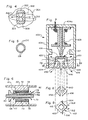
- Figure 1 is a perspective partially cutaway view of one presently preferred embodiment of the servovalve apparatus of the present invention.
- Figure 2 is vertical cross-sectional view of the embodiment of Figure 1 taken along lines 2-2 of Figure 1 which also includes a schematic illustration of an actuator device shown in broken lines.
- Figure 3 is a top, graphical view of a tip and receiving plate configuration for use with the apparatus of Figures 1 and 2.
- Figure 4 is a top, graphical view of another alternative tip and receiving plate configuration for use with the apparatus of Figures 1 and 2.
- Figure 5 is an end, cross-sectional view of the mandrel of the apparatus of Figures 1 and 2.
- Figure 6 is a cross-sectional view of an alternative arrangement of the armature and magnets of the servovalve apparatus of Figures 1 and 2.
- Figure 7 is a cross-sectional view of another presently preferred embodiment of the servovalve apparatus of the present invention.
- Figure 8 is a top, cross-sectional view of the channel configuration of the receiving plate of the apparatus of Figure 6 taken along lines 8--8 of Figure 7.
- Figure 9 is a top, cross-sectional view of the porting element of the apparatus of Figure 7 taken along lines 9--9 of Figure 7.
- servovalve 10 comprises a body 20 which may be formed of any suitable material. It is presently preferred that body 20 be formed of a soft magnetic material which is easy to machine and which has low hysteresis, such as, for example, silicon steel, leaded steel, or low carbon steel.
- body 20 could have a wide variety of different shapes and configurations, body 20 is illustrated herein as being substantially cylindrical. It is presently believed that the cylindrical configuration of body 20 facilitates the manufacture of servovalve 10, and is readily susceptible of being machined to accommodate the various component parts of servovalve 10, a described further below.
- End plate 30 may be formed of any suitable material, such as, for example, brass. End plate 30 is secured within the upstream end 20 of body 20 in some suitable manner such as by soldering or by means of an adhesive.
- End plate 30 is provided with a nipple 32, as shown, which may be attached to a source of pressurized fluid using a conventional fluid tube (not shown).
- An O-ring 33 preferably surrounds nipple 32 in a suitable groove to assist in sealing nipple 32 to the fluid tube.
- end plate 30 is provided with a spindle 34.
- Spindle 34 and nipple 32 may advantageously be formed as an integral part of end plate 30.
- nipple 32, end plate 30, and spindle 34 each have a bore therethrough which combine to form a substantially uniform, longitudinal passageway, the purpose of which will become more readily apparent from the discussion which follows.
- a mandrel 40 is provided on spindle 34 of end plate 30.
- Mandrel 40 may be formed of any suitable material such as, for example, steel, and could be formed as an integral part of end plate 30 or as a separate element.
- a downstream end disk 41 of the mandrel is made of a non-magnetic material such as aluminum, plastic, etc. The mandrel 40 will be further discussed hereafter.
- a suitable electrical conductor is wound around mandrel 40 so as to form a conductive coil.
- Any suitable electrical conductor may be used, such as, for example, # 30 copper magnet wire.
- the ends of wire 42 are then connected to suitable insulated wires 16 which pass out of body 20 through a suitable opening in end plate 30.
- wires 16 may be provided with some type of connector plug 18 for connecting wires 16 (and thus conductive coil 42) to a suitable source of electric current.
- a flexible conduit 60 passes through the central bore of end plate 30 and the central bore of the mandrel 40.
- the upstream end 62 of conduit 60 is secured within end plate 30 in some appropriate manner, such as, for example, by means of a conventional bushing 63.
- Conduit 60 may be formed of any suitable material, such as, for example, steel.
- An armature 64 is secured to conduit 60 so as to lie adjacent mandrel 40.
- Armature 64 may, for example, be formed of steel and may be slideably secured on conduit 40 by friction or by being soldered. Alternatively, armature 64 may be secured on conduit 60 by means of a suitable adhesive.
- Armature 64 may have virtually any suitable geometric configuration.
- armature 64 may be a substantially rectangular member as best seen in Figure 1. It is presently preferred that a portion of armature 64 near mandrel 40 be diametrically enlarged, as shown in Figures 1 and 2. It is believed that the diametrically enlarged portion of armature 64 will assist the armature in conducting the magnetic induction current necessary for the proper operation of servovalve 10, as described in more detail below.
- Magnets 72 and 73 are positioned on opposite sides of armature 64, as shown in Figure 2. Magnets 72 and 73 may, for example, be secured to body 20 by means of suitable magnet mounts 70. Significantly, one magnet 72 or 73 is configured and positioned such that it presents a north magnetic pole facing armature 64, while the other such magnet is configured and positioned so as to present a south magnetic pole facing armature 64. while magnets 72 and 73 could be formed of a wide variety of different materials, it is presently preferred that magnets 72 and 73 be formed of a rare earth metal material. It is believed that rare earth magnets facilitate making servovalve 10 small and lightweight due to their superior magnetic characteristics.
- conduit 60 The downstream end of conduit 60 is preferably provided with a tip 66 which may be formed of any suitable material, such as, for example, brass. Tip 66 is secured to conduit 60 in some suitable manner, such as by means of friction or by means of a suitable adhesive. Importantly, tip 66 is configured as a fluid orifice through which fluid may flow from conduit 60.
- the downstream end of body 20 is provided with a receiving plate 80 which may, for example, be formed of brass.
- Receiving plate 80 is secured within body 20 in some appropriate fashion, such as by means of solder or adhesive.
- Receiving plate 80 has one or more fluid channels or sets of channels 84 and 86 formed therein which terminate in openings 85 and 87, respectively (see Figure 1).
- Channels 84 and 86 advantageously originate within and communicate with an arcuate or concave socket 82 which is formed in the surface of receiving plate 80 inside body 20.
- the radius of curvature of socket 82 is substantially equal to the radius of curvature of the arcuate pathway over which the downstream end of conduit 60 moves during flexure, for reasons which will become more fully apparent from the discussion which follows.
- tip 66 and receiving plate 80 Although there will generally be some distance between tip 66 and receiving plate 80, it is preferable to minimize this distance in order to reduce the amount of fluid leakage from between tip 66 and receiving plate 80.
- the distance between tip 66 and receiving plate 80 is not so small, however, that substantial frictional forces between the tip 66 and receiving plate 80 are present or that a lubricating fluid must be used in servovalve 10.
- the distance between tip 66 and receiving plate 80 can also be maintained at a substantially constant minimal level during flexure of conduit 60.
- servovalve 10 When used in a fluid system, servovalve 10 is attached by means of nipple 32 to a source of pressurized fluid. The pressurized fluid then enters conduit 60 through nipple 32 and travels toward receiving plate 80.
- Conductive coil 42 is connected by means of wires 16 and plug 18 to a source of electricity. As electrical current flows through coil 42, a magnetic current is induced through the center of coil 42 in accordance with well-known principles of electromagnetism. Because of this induced magnetic current, armature 64 which is adjacent one end of coil 42 will be magnetized as either a north magnetic pole or a south magnetic pull depending upon the direction of the electrical current in coil 42. As a result, armature 64 will be magnetically attracted toward either magnet 72 or magnet 73, and conduit 60 will be deflected either upwardly or downwardly in Figure 2.
- the direction of the electrical current through coil 42 may cause armature 64 to be magnetized as a north magnetic pole.
- armature 64 will be magnetically repelled from magnet 72 and magnetically attracted toward magnet 73.
- conduit 60 will be deflected downwardly in Figure 2.
- Conduit 60 could, of course, also be deflected upwardly in Figure 2 in a similar fashion by simply reversing the direction of the electrical current in coil 42.
- eddy currents in the flux pathway are also developed, e.g., in the body 20 and mandrel 40, and any other conductive material located in the flux pathway.
- Such eddy currents produce a back electromotive force which slows buildup of the flux and thus the response time of the servovalve.
- elongate slots 76 ( Figure 1) are formed in the body 20 to extend generally parallel to the long axis of the body and to one another. These slots 76 serve to breakup the pathways over which the eddy currents would otherwise develop.
- An additional feature employed for disrupting the formation of eddy currents is to construct the mandrel 40 in laminate form, with laminations of conductive material 104 (Figure 5 shows an end cross-sectional view of the mandrel 40) separated by layers or coatings 108 of nonconductive material.
- the coatings 108 of nonconductive material breakup the pathways of the eddy currents to inhibit their formation.
- conduit 60 is deflected upwardly in Figure 2, fluid will flow through conduit 60 and through tip 66 into fluid channels 84.
- conduit 60 is deflected downwardly in Figure 2
- fluid will flow through conduit 60 and through tip 66 into channels 86.
- the flow of fluid into fluid channels 84 and 86 may be selectively controlled by simply controlling the direction of the electrical current in coil 42 which determines the direction conduit 60 is deflected.
- receiving plate 80 with a concave socket 82 which has a radius of curvature substantially equal to the radius of curvature of the pathway over which the downstream end of conduit 60 moves, a relatively close tolerance can be maintained between tip 66 and concave socket 82.
- the flow of fluid through conduit 60 can be virtually stopped by positioning conduit 60 as illustrated in Figure 2 such that the orifice (or orifices) formed by tip 66 lie between fluid channels 84 and 86. While some fluid leakage can still be expected, the fluid leakage will be minimal as compared with prior art jet pipe valves.
- the performance of servovalve 10 can approach that of conventional spool valves while being much less expensive and much easier to manufacture and maintain.
- an appropriate filter may be provided around tip 66.
- a conventional porous metal material may be provided around tip 66 to act as a filter for any magnetized particles in the fluid.
- a metal bellows 94 may be provided between body 20 and tip 66. Bellows 94 will still allow tip 66 to move within body 20, but will prevent any fluid from coming into contact with magnets 72 and 73.
- the fluid used in servovalve 10 may be virtually any fluid, including both air and water. However, if water is used, it also becomes important to insulate coil 42 from contact with the water. The use of a bellows 94 as could thus also serve to insulate coil 42 from water.
- servovalve 10 may be connected to a suitable actuator 12, if desired.
- the pressurized fluid can be directed through channel 14 so as to cause extension of piston rod 13 of actuator 12.
- Fluid could thereafter be directed through channel 86 in receiving plate 80 to channel 15 which would cause piston rod 13 to be retracted.
- an actuator 12 may be connected directly to servovalve 10 by means of a suitable sleeve (not shown).
- a suitable sleeve (not shown).
- an O-ring 26 may be provided around body 20, as shown.
- Figure 3 shows a top, graphical view of one embodiment of a receiving plate 204 and a tip 208 for more gradually increasing fluid flow from an orifice 212 in the tip into either channel 216 or channel 220, formed in the receiving plate 204, depending upon the direction of deflection of the tip 208.
- the channels 216 and 220 are formed with generally wedge-shaped cross-sections, as shown, with the narrower ends 216a and 220a being positioned nearest to one another, with the respective channels extending in opposite directions therefrom, again as shown.
- the tip 208 is dimensioned so that a small portion of the narrower ends 216a and 220a of the channels are exposed to the orifice 212, and so that the tip leaves uncovered small portions of the wider ends 216b and 220b are left uncovered by the tip.
- a small amount of fluid would flow continually from the orifice 212 into the channels 216 and 220 when the tip 208 is in an undeflected position (midway between the two channels).
- the tip 208 is deflected either to the left or right in Figure 4
- the exposure of the channels to the orifice 212 takes place gradually as the channel in question widens in the direction of movement of the tip. The fluid flow thus gradually increases from a trickle to the full amount desired.
- the tip 208 can be more stably controlled and moved.
- fluid flow begins abruptly, such as in conventional jet pipe valve arrangements, the end of the jet pipe can become unstable and vibrate or oscillate (such condition is known as flow force instability).
- flow force instability such condition is known as flow force instability.
- Figure 4 shows a top, graphical view of an alternative configuration for a receiving plate 304 and tip 308.
- the receiving plate 304 has two rows of three channels, 312 and 316 formed therein.
- the two rows of channels 312 and 316 are arranged generally parallel to one another and perpendicular or cross-wise to the direction of movement or deflection of the tip 308 indicated by the arrows in Figure 4.
- the tip 308 includes two orifices 320 and 324 positioned in a row midway between the two rows of channel 312 and 316, and offset from imaginary lines (such as line 328) joining adjacent channels of the two rows 312 and 316 (such as the top two adjacent channels). Again, it may be desirable to provide some overlap of the orifices 320 and 324 with adjacent channels 312 and 316 so that some fluid flow occurs even when the tip 308 is in the undeflected position.
- Figure 4 likewise allows for a gradual increase in the flow of fluid upon deflection of the tip 308 (either to the right or left in Figure 4). That is, the flow forces otherwise generated or, to a certain extent, moderated so that the likelihood of flow force instability is reduced.
- Figure 6 is a side, cross-sectional view of an alternative arrangement of the armature 64 and magnets 72 and 73 shown in Figure 2.
- a layer or plate of nonmagnetic material 74 and 75 (such as aluminum, plastic, etc.) disposed respectively over magnets 72 and 73.
- the effect of these layers 74 and 75 is to decrease the gap between the armature 64 and the respective magnets 72 and 73 to thereby produce a smaller pathway through which damping fluid (which might simply be air) may escape.
- the effect of this is to increase the damping, because of the close proximity of the armature 64 to the layers 74 and 75, with movement of the armature.
- damping pans 78 and 79 each having sidewalls and a bottom wall such as side walls 78a and bottom wall 78b, on the armature 60 to face and partially circumscribe corresponding layer 74 and magnet 72, and layer 75 and magnet 72.
- the damping fluid located in the cavity 77 must be moved out of the pan 78 as the pan approaches the layer 74 and magnet 72.
- the damping fluid is caused to flow from between the bottom of the pan 78 and the layer 74 outwardly as indicated by arrows 91 and 92, and since there is some resistance to the movement of this fluid, the movement of the armature towards layer 74 is dampened.
- damping helps to inhibit oscillation of the armature 64 which might otherwise be caused by the flow forces of the fluid through the conduit 60 and into selected receiving channels.
- FIG 7 is a cross-sectional view of another embodiment of a servovalve 400 made in accordance with the present invention, showing primarily only those features which are different from the embodiment of Figures 1 and 2.
- the servovalve 400 includes a casing 404 in which are contained a mandrel and coil (not shown) surrounding a valve stem or element 408 which extends forwardly from the back wall 404a of the casing.
- the valve element 408 is an elongate rod made of a flexible and resilient material similar to the conduit 60 of Figures 1 and 2.
- the casing 404 and valve element 408 are made of a material having substantially the same thermal coefficient of expansion so that any change in temperature which would tend to change the long dimensions of the casing 404 would also tend to correspondingly change the length of the valve element 408 so that the close tolerance is designed into servovalve 400 or maintained.
- Mounted on the end of the valve element 408 is a porting cup 412 having an interior hollow 416 circumscribed by side walls 420 which terminate in a cup rim 424.
- the width of the hollow 416 increases with increasing depth in the porting cup 412. That is, the width of the hollow 416 at the rim 424 is less than the width of the bottom of the hollow.
- a receiving plate 428 Disposed adjacent to the porting cup 412 is a receiving plate 428 having an arcuate surface area 430 adjacent to which the porting cup 412 moves when deflected.
- the receiving plate 428 includes two fluid channels 432 and 436 positioned on opposite sides of an input fluid orifice 440.
- the fluid stream which in the embodiment of Figures 1 and 2 was carried in a conduit 60, is directed by the orifice 440 and the receiving plate 428 toward the porting cup 412.
- the orifice 440 would be connected to a suitable source of fluid under pressure.
- the fluid channels 432 and 436 likewise would be coupled to a suitable actuation device as shown in Figure 2.
- FIG. 7 Also aiding in reducing flow force instability in the embodiment of Figure 7 is the top cross-sectional shape of both the porting cup 412 and the channels 432 and 436.
- a cross-sectional view of the channels 432 and 436, and of the orifice 440, taken along lines 8--8 of Figure 7 is shown in Figure 8.
- a cross-sectional view of the porting cup 412 taken along lines 9--9 of Figure 7 is shown in Figure 9.
- the cross-sections of the two channels 432 and 436 are shaped as facing, right-angle openings on either side of the orifice 440.
- the top, cross-sectional configuration of the porting cup 412 is generally rectangular as shown in Figure 9 so that when the porting cup is in the undeflected position, the rim 424 of the side wall 420 substantially covers the channel openings 432 and 436.
- the fluid stream enters the hollow 416 to apply a force to the inside surface of the side wall 420.
- These forces are illustrated in Figure 9 with arrows 504, 508, 512 and 516.
- the forces represented by arrows 504 and 516 cancel leaving only the forces represented by arrows 508 and 512 which are in the direction of deflection of the porting cup 412.
- the present invention provides a servovalve apparatus which can readily be used with high fluid flow rates and which can provide relatively high power output but which does not require the very tight tolerances of many prior art valve devices. It has, for example, been found that the servovalve apparatus of the present invention may easily be used with fluid flow rates within the range of from approximately one gallon per minute to approximately four gallons per minute. This is ten to forty times greater than the fluid flow rates typically used with conventional jet pipe valves.
- the servovalve apparatus Since tight tolerances are not required in the servovalve apparatus of the present invention, the servovalve apparatus is relatively inexpensive, and it is much easier to manufacture and maintain than many conventional valves. Also, friction and the wear that can result therefrom when tight tolerances are required is avoided with the present invention. At the same time, however, the performance of the servovalve apparatus of the present invention approximates in many respects the performance of much more expensive, conventional spool valves.
- the physical configuration of the servovalve apparatus of the present invention also makes it possible to construct the servovalve apparatus much smaller than many conventional valves.
- the small size and relatively light weight of the servovalve apparatus is also achieved in part due to the use of rare earth magnets within the servovalve apparatus.
Landscapes
- Engineering & Computer Science (AREA)
- General Engineering & Computer Science (AREA)
- Theoretical Computer Science (AREA)
- Physics & Mathematics (AREA)
- Fluid Mechanics (AREA)
- Mechanical Engineering (AREA)
- Servomotors (AREA)
- Magnetically Actuated Valves (AREA)
- Control Of Fluid Pressure (AREA)
- Multiple-Way Valves (AREA)
- Fluid-Pressure Circuits (AREA)
Abstract
Description
- This invention relates to a novel servovalve apparatus for use in fluid systems to selectively direct or "port" fluid flow.
- Fluid systems are frequently used in mechanical devices as a means of controlling or positioning various mechanical components. As used herein, the term "fluid" is used generally to refer to any substance which is capable of flowing under pressure through a conduit. Thus, the term "fluid" encompasses both gasses and liquids, and the general term "fluid systems" is intended to include both pneumatic and hydraulic systems.
- A fluid system typically comprises a pump for pressurizing the fluid which is then used to provide the force necessary to position and/or control a desired mechanical component. For example hydraulic systems are often used to control shovels or scoops on heavy construction machinery. Similarly, pneumatic systems are frequently employed in the field of robotics to control the position and movement of a desired object, such as, for example, a robotic arm.
- Appropriate fluid controlling valves are essential for the proper operation of virtually all fluid systems. For example, a valve may be used to direct pressurized fluid first to one side and then the other of a plunger which is slideably positioned within an elongated housing. The operation of the valve thus controls the flow of pressurized fluid to each side of the plunger and thereby the position of the plunger within the housing.
- Examples of some of the more commonly used valves in fluid systems are poppet valves (which control fluid flow by a "pinching" action) and spool valves (which control fluid flow by selective alignment of fluid channels in a spool with orifices in a sleeve in which the spool is slideably disposed). Poppet valves are generally not well suited for servovalve applications, typically have a significant lag time in their operation, and many times have leakage problems. Spool valves require very tight tolerances to avoid leakage between the spool and sleeve thus making them expensive to manufacture and maintain. Also, because of the tight tolerances, significant frictional forces can be generated causing wear in the valves.
- A valve having somewhat more recent origin is the jet pipe valve, often called a flow-dividing valve. A jet pipe valve comprises a fluid pipe having a small orifice on its downstream end. Fluid flows through the pipe at a substantially constant rate, and the small orifice produces a "jet" of fluid out of the end of the pipe. The pipe is provided with a suitable actuator device which selectively directs the fluid jet toward one or more nearby fluid paths. By appropriately positioning the fluid pipe, the ratio of fluid flowing into the nearby fluid paths can be controlled.
- Conventional jet pipe valves suffer from significant fluid leakage and are quite inefficient in their use of fluid power. The operation of jet pipe valves is also somewhat unpredictable, and can be unstable, at high pressures and high fluid flow rates. Consequently, prior art jet pipe valves typically incorporate small orifices (less than .005") and operate at fluid flow rates on the order of 0.1 gallons per minute. Conventional jet pipe valves are also typically quite bulky. Due to the significant tangential forces present in jet pipe valves, bulky mechanical actuators are often used. Torsional springs and other balancing mechanisms are also often employed in jet pipe valves in an effort to improve valve operation. Consequently, prior art jet pipe valves are often very difficult to properly maintain and adjust during use.
- It is an object of the invention to provide a servovalve apparatus for use in fluid systems and capable of providing high power output.
- It is also an object of the invention to provide such a system capable of operating stably under high fluid flow rates but which does not require the maintenance of tight tolerances between the valve's component parts.
- It is an additional object of the invention to provide a substantially frictionless-operating servovalve apparatus.
- It is another object of the invention to provide a servovalve apparatus in which fluid flow forces are reduced.
- It is still another object of the invention to provide an efficient servovalve apparatus for use in fluid systems which is simple in construction and inexpensive to manufacture and maintain.
- It is a further object of the invention to provide a servovalve apparatus for use in fluid systems which is both lightweight and compact in size.
- In accordance with the foregoing objects, one illustrative embodiment of the present invention comprises an elongate flexible valve stem or element having a fixed end and a free end which is moveable back and forth along a generally arcuate path. A receiving plate is provided to define a generally arcuate surface area adjacent the arcuate path over which the free end of the valve element moves. The receiving plate has a bore formed therein for directing a fluid stream toward the free end of the valve element, and at least one fluid channel terminating at a location along the arcuate surface area. A porting element is disposed on the free end of the valve element to guide or port the fluid stream from the bore into the fluid channel when the free end is deflected or moved to a certain position over the receiving plate. Apparatus for selectively deflecting the free end of the valve element to the said certain position (and out of said certain position) is also provided.
- The apparatus for selectively deflecting the free end of the valve element could, in accordance with one aspect of the invention, include an armature affixed to the valve element near the free end thereof, a conductive coil which surrounds at least a portion of the valve element adjacent its free end, and a magnet assembly disposed adjacent the armature on at least one side thereof. A source of electrical current supplies current to the conductive coil to magnetize the armature and thus cause it to either be attracted toward or repelled from the magnet assembly. In this manner, the porting element may be selectively positioned over the fluid channel in the receiving plate or moved away therefrom.
- These and other objects and features of the present invention will become more fully apparent from the following description and appended claims, taken in conjunction with the accompanying drawings.
- Figure 1 is a perspective partially cutaway view of one presently preferred embodiment of the servovalve apparatus of the present invention.
- Figure 2 is vertical cross-sectional view of the embodiment of Figure 1 taken along lines 2-2 of Figure 1 which also includes a schematic illustration of an actuator device shown in broken lines.
- Figure 3 is a top, graphical view of a tip and receiving plate configuration for use with the apparatus of Figures 1 and 2.
- Figure 4 is a top, graphical view of another alternative tip and receiving plate configuration for use with the apparatus of Figures 1 and 2.
- Figure 5 is an end, cross-sectional view of the mandrel of the apparatus of Figures 1 and 2.
- Figure 6 is a cross-sectional view of an alternative arrangement of the armature and magnets of the servovalve apparatus of Figures 1 and 2.
- Figure 7 is a cross-sectional view of another presently preferred embodiment of the servovalve apparatus of the present invention.
- Figure 8 is a top, cross-sectional view of the channel configuration of the receiving plate of the apparatus of Figure 6 taken along lines 8--8 of Figure 7.
- Figure 9 is a top, cross-sectional view of the porting element of the apparatus of Figure 7 taken along lines 9--9 of Figure 7.
- The presently preferred embodiments of the invention will be best understood by reference to the drawings, wherein like parts are designated with like numerals throughout.
- One presently preferred embodiment of the servovalve apparatus of the present invention, designated generally at 10, is illustrated in Figures 1 and 2. As shown,
servovalve 10 comprises abody 20 which may be formed of any suitable material. It is presently preferred thatbody 20 be formed of a soft magnetic material which is easy to machine and which has low hysteresis, such as, for example, silicon steel, leaded steel, or low carbon steel. - While
body 20 could have a wide variety of different shapes and configurations,body 20 is illustrated herein as being substantially cylindrical. It is presently believed that the cylindrical configuration ofbody 20 facilitates the manufacture ofservovalve 10, and is readily susceptible of being machined to accommodate the various component parts ofservovalve 10, a described further below. - The
upstream end 29 ofbody 20 is provided with anend plate 30, as illustrated in Figure 2.End plate 30 may be formed of any suitable material, such as, for example, brass.End plate 30 is secured within theupstream end 20 ofbody 20 in some suitable manner such as by soldering or by means of an adhesive. -
End plate 30 is provided with anipple 32, as shown, which may be attached to a source of pressurized fluid using a conventional fluid tube (not shown). An O-ring 33 preferably surroundsnipple 32 in a suitable groove to assist in sealingnipple 32 to the fluid tube. -
Opposite nipple 32,end plate 30 is provided with aspindle 34.Spindle 34 andnipple 32 may advantageously be formed as an integral part ofend plate 30. Significantly,nipple 32,end plate 30, andspindle 34 each have a bore therethrough which combine to form a substantially uniform, longitudinal passageway, the purpose of which will become more readily apparent from the discussion which follows. - A
mandrel 40 is provided onspindle 34 ofend plate 30.Mandrel 40 may be formed of any suitable material such as, for example, steel, and could be formed as an integral part ofend plate 30 or as a separate element. Adownstream end disk 41 of the mandrel is made of a non-magnetic material such as aluminum, plastic, etc. Themandrel 40 will be further discussed hereafter. - A suitable electrical conductor is wound around
mandrel 40 so as to form a conductive coil. Any suitable electrical conductor may be used, such as, for example, # 30 copper magnet wire. The ends ofwire 42 are then connected to suitableinsulated wires 16 which pass out ofbody 20 through a suitable opening inend plate 30. As shown in Figure 1,wires 16 may be provided with some type ofconnector plug 18 for connecting wires 16 (and thus conductive coil 42) to a suitable source of electric current. - As illustrated in Figure 2, a
flexible conduit 60 passes through the central bore ofend plate 30 and the central bore of themandrel 40. The upstream end 62 ofconduit 60 is secured withinend plate 30 in some appropriate manner, such as, for example, by means of aconventional bushing 63.Conduit 60 may be formed of any suitable material, such as, for example, steel. - An
armature 64 is secured toconduit 60 so as to lieadjacent mandrel 40.Armature 64 may, for example, be formed of steel and may be slideably secured onconduit 40 by friction or by being soldered. Alternatively,armature 64 may be secured onconduit 60 by means of a suitable adhesive. -
Armature 64 may have virtually any suitable geometric configuration. For example,armature 64 may be a substantially rectangular member as best seen in Figure 1. It is presently preferred that a portion ofarmature 64 nearmandrel 40 be diametrically enlarged, as shown in Figures 1 and 2. It is believed that the diametrically enlarged portion ofarmature 64 will assist the armature in conducting the magnetic induction current necessary for the proper operation ofservovalve 10, as described in more detail below. - Two
magnets armature 64, as shown in Figure 2.Magnets body 20 by means of suitable magnet mounts 70. Significantly, onemagnet pole facing armature 64, while the other such magnet is configured and positioned so as to present a south magneticpole facing armature 64. whilemagnets magnets servovalve 10 small and lightweight due to their superior magnetic characteristics. - The downstream end of
conduit 60 is preferably provided with atip 66 which may be formed of any suitable material, such as, for example, brass.Tip 66 is secured toconduit 60 in some suitable manner, such as by means of friction or by means of a suitable adhesive. Importantly,tip 66 is configured as a fluid orifice through which fluid may flow fromconduit 60. - The downstream end of
body 20 is provided with a receivingplate 80 which may, for example, be formed of brass. Receivingplate 80 is secured withinbody 20 in some appropriate fashion, such as by means of solder or adhesive. - Receiving
plate 80 has one or more fluid channels or sets ofchannels openings Channels concave socket 82 which is formed in the surface of receivingplate 80 insidebody 20. Preferably, the radius of curvature ofsocket 82 is substantially equal to the radius of curvature of the arcuate pathway over which the downstream end ofconduit 60 moves during flexure, for reasons which will become more fully apparent from the discussion which follows. - Although there will generally be some distance between
tip 66 and receivingplate 80, it is preferable to minimize this distance in order to reduce the amount of fluid leakage from betweentip 66 and receivingplate 80. The distance betweentip 66 and receivingplate 80 is not so small, however, that substantial frictional forces between thetip 66 and receivingplate 80 are present or that a lubricating fluid must be used inservovalve 10. Significantly, by providing receivingplate 80 with asocket 82, as described above, the distance betweentip 66 and receivingplate 80 can also be maintained at a substantially constant minimal level during flexure ofconduit 60. - When used in a fluid system, servovalve 10 is attached by means of
nipple 32 to a source of pressurized fluid. The pressurized fluid then entersconduit 60 throughnipple 32 and travels toward receivingplate 80. -
Conductive coil 42 is connected by means ofwires 16 and plug 18 to a source of electricity. As electrical current flows throughcoil 42, a magnetic current is induced through the center ofcoil 42 in accordance with well-known principles of electromagnetism. Because of this induced magnetic current,armature 64 which is adjacent one end ofcoil 42 will be magnetized as either a north magnetic pole or a south magnetic pull depending upon the direction of the electrical current incoil 42. As a result,armature 64 will be magnetically attracted toward eithermagnet 72 ormagnet 73, andconduit 60 will be deflected either upwardly or downwardly in Figure 2. - For example, the direction of the electrical current through
coil 42 may causearmature 64 to be magnetized as a north magnetic pole. Thus, ifmagnet 72 is positioned so as to present a north magneticpole facing armature 64 andmagnet 73 is positioned so as to present a south magneticpole facing armature 64,armature 64 will be magnetically repelled frommagnet 72 and magnetically attracted towardmagnet 73. As a result,conduit 60 will be deflected downwardly in Figure 2.Conduit 60 could, of course, also be deflected upwardly in Figure 2 in a similar fashion by simply reversing the direction of the electrical current incoil 42. - As a result of supplying electrical current to the
coil 42 to develop magnet flux, eddy currents in the flux pathway are also developed, e.g., in thebody 20 andmandrel 40, and any other conductive material located in the flux pathway. Such eddy currents produce a back electromotive force which slows buildup of the flux and thus the response time of the servovalve. In order to interfere with and disrupt the production of such eddy currents, elongate slots 76 (Figure 1) are formed in thebody 20 to extend generally parallel to the long axis of the body and to one another. Theseslots 76 serve to breakup the pathways over which the eddy currents would otherwise develop. - An additional feature employed for disrupting the formation of eddy currents is to construct the
mandrel 40 in laminate form, with laminations of conductive material 104 (Figure 5 shows an end cross-sectional view of the mandrel 40) separated by layers orcoatings 108 of nonconductive material. Thecoatings 108 of nonconductive material breakup the pathways of the eddy currents to inhibit their formation. - It will be readily appreciated that if
conduit 60 is deflected upwardly in Figure 2, fluid will flow throughconduit 60 and throughtip 66 intofluid channels 84. On the other hand, ifconduit 60 is deflected downwardly in Figure 2, fluid will flow throughconduit 60 and throughtip 66 intochannels 86. Thus, the flow of fluid intofluid channels coil 42 which determines thedirection conduit 60 is deflected. - Advantageously, as mentioned above, by providing receiving
plate 80 with aconcave socket 82 which has a radius of curvature substantially equal to the radius of curvature of the pathway over which the downstream end ofconduit 60 moves, a relatively close tolerance can be maintained betweentip 66 andconcave socket 82. As a result, the flow of fluid throughconduit 60 can be virtually stopped by positioningconduit 60 as illustrated in Figure 2 such that the orifice (or orifices) formed bytip 66 lie betweenfluid channels servovalve 10 can approach that of conventional spool valves while being much less expensive and much easier to manufacture and maintain. - As noted above, there will likely be at least some fluid which leaks into the interior of
body 20 from the orifice (or orifices) formed bytip 66. Such fluid may occasionally contain magnetized particles which could travel towardmagnets servovalve 10. - In order to prevent magnetic particles from coming into contact with
magnets tip 66. For example, a conventional porous metal material may be provided aroundtip 66 to act as a filter for any magnetized particles in the fluid. Alternatively, a metal bellows 94 may be provided betweenbody 20 andtip 66. Bellows 94 will still allowtip 66 to move withinbody 20, but will prevent any fluid from coming into contact withmagnets - Unlike many prior art devices, the fluid used in
servovalve 10 may be virtually any fluid, including both air and water. However, if water is used, it also becomes important to insulatecoil 42 from contact with the water. The use of abellows 94 as could thus also serve to insulatecoil 42 from water. - As shown schematically in Figure 2, servovalve 10 may be connected to a
suitable actuator 12, if desired. Thus, by directing fluid throughchannel 84 in receivingplate 80, the pressurized fluid can be directed throughchannel 14 so as to cause extension of piston rod 13 ofactuator 12. Fluid could thereafter be directed throughchannel 86 in receivingplate 80 to channel 15 which would cause piston rod 13 to be retracted. - Advantageously, an
actuator 12 may be connected directly to servovalve 10 by means of a suitable sleeve (not shown). In such case, in order to facilitate sealing the sleeve around the downstream end 28 ofbody 20, an O-ring 26 may be provided aroundbody 20, as shown. - Figure 3 shows a top, graphical view of one embodiment of a receiving
plate 204 and atip 208 for more gradually increasing fluid flow from anorifice 212 in the tip into eitherchannel 216 orchannel 220, formed in the receivingplate 204, depending upon the direction of deflection of thetip 208. Thechannels tip 208 is dimensioned so that a small portion of the narrower ends 216a and 220a of the channels are exposed to theorifice 212, and so that the tip leaves uncovered small portions of the wider ends 216b and 220b are left uncovered by the tip. With this configuration, a small amount of fluid would flow continually from theorifice 212 into thechannels tip 208 is in an undeflected position (midway between the two channels). As thetip 208 is deflected either to the left or right in Figure 4, it is evident that the exposure of the channels to theorifice 212 takes place gradually as the channel in question widens in the direction of movement of the tip. The fluid flow thus gradually increases from a trickle to the full amount desired. The effect of this is that thetip 208 can be more stably controlled and moved. When fluid flow begins abruptly, such as in conventional jet pipe valve arrangements, the end of the jet pipe can become unstable and vibrate or oscillate (such condition is known as flow force instability). With the configuration of Figure 4, the likelihood of such instability is reduced. - Figure 4 shows a top, graphical view of an alternative configuration for a receiving
plate 304 andtip 308. Here, the receivingplate 304 has two rows of three channels, 312 and 316 formed therein. - The two rows of
channels tip 308 indicated by the arrows in Figure 4. Thetip 308 includes twoorifices channel rows 312 and 316 (such as the top two adjacent channels). Again, it may be desirable to provide some overlap of theorifices adjacent channels tip 308 is in the undeflected position. As with the Figure 3 configuration, the arrangement of Figure 4 likewise allows for a gradual increase in the flow of fluid upon deflection of the tip 308 (either to the right or left in Figure 4). That is, the flow forces otherwise generated or, to a certain extent, moderated so that the likelihood of flow force instability is reduced. - Figure 6 is a side, cross-sectional view of an alternative arrangement of the
armature 64 andmagnets nonmagnetic material 74 and 75 (such as aluminum, plastic, etc.) disposed respectively overmagnets layers armature 64 and therespective magnets armature 64 to thelayers pans 78 and 79, each having sidewalls and a bottom wall such asside walls 78a and bottom wall 78b, on thearmature 60 to face and partially circumscribe correspondinglayer 74 andmagnet 72, andlayer 75 andmagnet 72. As thearmature 60 is deflected, for example towardlayer 74 andmagnet 72, the damping fluid located in thecavity 77 must be moved out of thepan 78 as the pan approaches thelayer 74 andmagnet 72. In order to get out of the way, the damping fluid is caused to flow from between the bottom of thepan 78 and thelayer 74 outwardly as indicated byarrows layer 74 is dampened. Such damping helps to inhibit oscillation of thearmature 64 which might otherwise be caused by the flow forces of the fluid through theconduit 60 and into selected receiving channels. - Figure 7 is a cross-sectional view of another embodiment of a
servovalve 400 made in accordance with the present invention, showing primarily only those features which are different from the embodiment of Figures 1 and 2. Theservovalve 400 includes a casing 404 in which are contained a mandrel and coil (not shown) surrounding a valve stem or element 408 which extends forwardly from the back wall 404a of the casing. The valve element 408 is an elongate rod made of a flexible and resilient material similar to theconduit 60 of Figures 1 and 2. Advantageously, the casing 404 and valve element 408 are made of a material having substantially the same thermal coefficient of expansion so that any change in temperature which would tend to change the long dimensions of the casing 404 would also tend to correspondingly change the length of the valve element 408 so that the close tolerance is designed intoservovalve 400 or maintained. Mounted on the end of the valve element 408 is a portingcup 412 having an interior hollow 416 circumscribed byside walls 420 which terminate in acup rim 424. The width of the hollow 416 increases with increasing depth in the portingcup 412. That is, the width of the hollow 416 at therim 424 is less than the width of the bottom of the hollow. - Disposed adjacent to the porting
cup 412 is a receivingplate 428 having an arcuate surface area 430 adjacent to which the portingcup 412 moves when deflected. The receivingplate 428 includes twofluid channels input fluid orifice 440. The fluid stream, which in the embodiment of Figures 1 and 2 was carried in aconduit 60, is directed by theorifice 440 and the receivingplate 428 toward the portingcup 412. Of course, theorifice 440 would be connected to a suitable source of fluid under pressure. Thefluid channels - When in the undeflected position shown in Figure 7, a fluid stream carried in the
orifice 440 would be blocked by the portingcup 412. But when the valve element 408 and portingcup 412 are deflected (either to the left or right in Figure 7) the fluid stream carried in theorifice 440 is guided or ported from the orifice into one of thechannels cup 412 is reduced. - Also aiding in reducing flow force instability in the embodiment of Figure 7 is the top cross-sectional shape of both the porting
cup 412 and thechannels channels orifice 440, taken along lines 8--8 of Figure 7 is shown in Figure 8. A cross-sectional view of the portingcup 412 taken along lines 9--9 of Figure 7 is shown in Figure 9. As indicated in Figure 8, the cross-sections of the twochannels orifice 440. The top, cross-sectional configuration of the portingcup 412 is generally rectangular as shown in Figure 9 so that when the porting cup is in the undeflected position, therim 424 of theside wall 420 substantially covers thechannel openings cup 412 is deflected to either side, the fluid stream enters the hollow 416 to apply a force to the inside surface of theside wall 420. These forces are illustrated in Figure 9 witharrows arrows 504 and 516 cancel leaving only the forces represented byarrows cup 412. If the angle between the side wall sections on which the force arrows are shown in Figure 9 is made even smaller, than the forces represented byarrows 504 and 516 would increase, but still cancel, and the forces represented byarrows cup 412 would thus result in a reduction of flow force instability. In any case, it can be seen that with the configuration of the portingcup 412 as shown in Figure 9 and the angular positions of different sections of theside wall 420 relative to one another, flow force instability can be reduced. - From the above discussion, it will be appreciated that the present invention provides a servovalve apparatus which can readily be used with high fluid flow rates and which can provide relatively high power output but which does not require the very tight tolerances of many prior art valve devices. It has, for example, been found that the servovalve apparatus of the present invention may easily be used with fluid flow rates within the range of from approximately one gallon per minute to approximately four gallons per minute. This is ten to forty times greater than the fluid flow rates typically used with conventional jet pipe valves.
- Since tight tolerances are not required in the servovalve apparatus of the present invention, the servovalve apparatus is relatively inexpensive, and it is much easier to manufacture and maintain than many conventional valves. Also, friction and the wear that can result therefrom when tight tolerances are required is avoided with the present invention. At the same time, however, the performance of the servovalve apparatus of the present invention approximates in many respects the performance of much more expensive, conventional spool valves.
- The physical configuration of the servovalve apparatus of the present invention also makes it possible to construct the servovalve apparatus much smaller than many conventional valves. The small size and relatively light weight of the servovalve apparatus is also achieved in part due to the use of rare earth magnets within the servovalve apparatus.
- The invention may be embodied in other specific forms without departing from its spirit or essential characteristics. The described embodiments are to be considered in all respects only as illustrative and not restrictive. The scope of the invention is, therefore, indicated by the appended claims, rather than by the foregoing description. All changes which come within the meaning and range of equivalency of the claims are to be embraced within their scope.
Claims (28)
- A servovalve apparatus for use in fluid systems in controlling the flow of a fluid stream comprising
an elongate flexible valve element having a fixed end and a free end which is moveable back and forth along a generally arcuate path,
receiving plate means which defines a generally arcuate surface area adjacent to the arcuate path, said receiving plate means having a bore terminating at a location along the arcuate surface area for carrying the fluid stream to the arcuate path, and at least one fluid channel terminating at the arcuate surface area adjacent to the bore,
cup means mounted on the free end of the valve element for receiving the fluid stream from the bore and porting it into the fluid channel when the free end is deflected to a certain position, and
means for selectively deflecting the free end of the valve element to said certain position and out of said certain position. - Apparatus as in Claim 1 wherein the cup means is formed with a hollow and a sidewall circumscribing the hollow, said hollow facing the receiving plate means with the rim of the sidewall disposed adjacent to the arcuate surface area.
- Apparatus as in Claim 2 wherein the hollow of the cup means widens with depth into the cup means.
- Apparatus as in Claim 2 wherein the receiving plate means has two fluid channels, each positioned on a respective opposite side of the bore, and wherein the rim of the sidewall of the cup means substantially covers the channel openings when the valve element is undeflected.
- Apparatus as in Claim 4 wherein the hollow of said cup means is formed to have a generally rectangular top cross-section.
- Apparatus as in Claim 5 wherein the two fluid channels are formed to have right-angle shaped cross-sections at the surface of the receiving plate positioned to partially surround the bore on opposite sides thereof.
- Apparatus as in Claim 1 wherein said deflecting means comprises
a conductive coil surrounding at least a portion of the valve element adjacent its fixed end for receiving electrical current,
an armature affixed to the valve element near its free end, and
a magnet assembly positioned at one side of the armature for selectively attracting or repelling the armature to deflect the valve element, depending upon the direction of electrical current received by the coil. - Apparatus as in Claim 7 wherein said magnet assembly comprises a first magnet and a second magnet, said first and second magnets being positioned on substantially opposite sides of the valve element, the first magnet being positioned such that a north magnetic pole faces the armature and the second magnet being positioned such that a south magnetic pole faces the armature.
- Apparatus as in Claim 8 further comprising first and second pans disposed on the armature in facing relationship with the first and second magnets, said pans each having a bottom wall and sidewalls which at least partially circumscribe a corresponding magnet.
- Apparatus as in Claim 9 further comprising first and second layers of nonmagnetic material disposed over the first and second magnets respectively to face the first and second pans respectively.
- Apparatus as in Claim 7 wherein the conductive coil comprises
a mandrel surrounding at least a portion of the valve element adjacent its fixed end; and
an electrical conductor wound around the mandrel so as to form a conductive coil. - Apparatus as in Claim 11 wherein the mandrel is constructed of laminates of conductive material, with nonconductive material disposed between the laminates, said laminates extending from one end of the mandrel to the other end.
- Apparatus as in Claim 7 further comprising means for preventing magnetic particles from coming into contact with the magnet assembly.
- Apparatus as in Claim 13 wherein the means for preventing magnetic particles from coming into contact with the magnet assembly comprises a bellows positioned between the free end of the valve element and the magnet assembly.
- A servovalve apparatus for use in fluid systems, comprising
a hollow, substantially cylindrical casing made of a magnetic material and having a plurality of slots formed to extend generally parallel with the longitudinal axis of the casing,
an elongate, flexible valve element positioned within the cylindrical casing so as to be substantially coaxial with the longitudinal axis of the casing, the valve element having a fixed end and a free end and being made of a material having a thermal coefficient of expansion substantially the same as that of the material from which the casing is made,
a mandrel surrounding at least a portion of the valve element adjacent its fixed end,
an electrical conductor wound around the mandrel so as to form a conductive coil,
an armature affixed to the valve element near the free end thereof,
a first magnet and a second magnet positioned on substantially opposite sides of the valve element, the first magnet being positioned such that a north magnetic pole faces the armature and the second magnet being positioned such that a south magnetic pole faces the armature,
a receiving plate positioned adjacent the free end of the valve element, the receiving plate having at least one fluid channel formed therein, and
a porting element secured to the free end of the valve element for porting a fluid stream received by the porting element into the fluid channel. - A servovalve apparatus as defined in Claim 15 further comprising means for preventing magnetic particles from coming into contact with the first and second magnets.
- A servovalve apparatus as defined in Claim 15 wherein the mandrel is constructed of laminates of conductive material, with the joined surfaces of the laminates being coated with a nonconductive coating, said laminates extending from one end of the mandrel to the other end.
- A servovalve apparatus for use in fluid systems in controlling the flow of a fluid stream comprising
a flexible conduit having an upstream end and a downstream end which is deflectable along a generally arcuate path from a null position to a first or second position on either side of the null position,
means for connecting a source of fluid to the upstream end of the conduit,
a receiving plate which defines a generally arcuate surface area adjacent to the arcuate path, said receiving plate having two generally parallel rows of two or more fluid channels with generally circular cross-sections and terminating in the arcuate surface area, said rows positioned generally cross-wise to the arcuate surface area and to the direction of deflection of the downstream end of the conduit,
tip means disposed on the downstream end of the conduit and formed with one or more orifices normally disposed adjacent to the arcuate surface area between the two rows of channels when the conduit is in the null position, with said one or more orifices normally being positioned offset from an imaginary line joining arcuately adjacent channels of each row, and
means for selectively deflecting the downstream end of the conduit to the first position or second position to thereby selectively direct fluid flowing through the conduit to one row of channels or the other. - Apparatus as in Claim 18 wherein said orifices in the tip partially overlap the respective closest channel openings in the arcuate surface area.
- A servovalve apparatus for use in fluid systems in controlling the flow of a fluid stream comprising
a flexible conduit having an upstream end and a downstream end which is deflectable along a generally arcuate path from a null position to a first or second position on either side of the null position,
means for connecting a source of fluid to the upstream end of the conduit,
a receiving plate which defines a generally arcuate surface area adjacent to the arcuate path, said receiving plate having two fluid channels spaced apart along the arcuate surface area, said channels having generally wedge-shaped cross-sections each of whose widths increase in the direction away from the other channel so that adjacent sides of the channels are narrowest and nonadjacent sides are widest,
tip means disposed on the downstream end of the conduit and formed with an orifice normally disposed adjacent the arcuate surface area between the two channels when the conduit is in the null position, and
means for selectively deflecting the downsteam end of the conduit to the first position or second position to thereby selectively direct fluid from the conduit to one channel or the other. - Apparatus as in Claim 20 wherein the tip comprises a body of material, one side of which is shaped to generally conform to the arcuate surface area of the receiving plate, said body and orifice being formed such that in the null position, the body covers a central portion of each channel opening, leaving the narrowest side and widest side uncovered.
- Apparatus as in Claims 18 or 20 wherein said deflecting means comprises
a conductive coil surrounding at least a portion of the conduit adjacent its upstream end for receiving electrical current,
an armature affixed to the conduit near its downstream end, and
a magnet assembly positioned at one side of the armature for selectively attracting or repelling the armature to deflect the conduit, depending upon the direction of electrical current received by the coil. - Apparatus as in Claim 22 wherein said magnet assembly comprises a first magnet and a second magnet, said first and second magnets being positioned on substantially opposite sides of the conduit, the first magnet being positioned such that a north magnetic pole faces the armature and the second magnet being positioned such that a south magnetic pole faces the armature.
- Apparatus as in Claim 23 further comprising first and second pans disposed on the armature in facing relationship with the first and second magnets, said pans each having a bottom wall and sidewalls which at least partially circumscribe a corresponding magnet.
- Apparatus as in Claim 22 wherein the conductive coil comprises
a mandrel surrounding at least a portion of the conduct adjacent its upstream end; and
an electrical conductor wound around the mandrel so as to form a conductive coil. - Apparatus as in Claim 25 wherein the mandrel is constructed of laminates of conductive material, with nonconductive material disposed between the laminates, said laminates extending from one end of the mandrel to the other end.
- Apparatus as in Claim 22 further comprising means for preventing magnetic particles from coming into contact with the magnet assembly.
- Apparatus as in Claim 27 wherein the means for preventing magnetic particles from coming into contact with the magnet assembly comprises a bellows positioned between the downstream end of the conduit and the magnet assembly.
Priority Applications (1)
| Application Number | Priority Date | Filing Date | Title |
|---|---|---|---|
| EP9494110901A EP0622550A3 (en) | 1990-01-31 | 1991-01-30 | Improved servovalve apparatus for use in fluid systems. |
Applications Claiming Priority (2)
| Application Number | Priority Date | Filing Date | Title |
|---|---|---|---|
| US473301 | 1990-01-31 | ||
| US07/473,301 US5012836A (en) | 1990-01-31 | 1990-01-31 | Servovalve apparatus for use in fluid systems |
Related Child Applications (1)
| Application Number | Title | Priority Date | Filing Date |
|---|---|---|---|
| EP94110901.9 Division-Into | 1994-07-13 |
Publications (2)
| Publication Number | Publication Date |
|---|---|
| EP0440194A1 true EP0440194A1 (en) | 1991-08-07 |
| EP0440194B1 EP0440194B1 (en) | 1995-04-05 |
Family
ID=23879001
Family Applications (2)
| Application Number | Title | Priority Date | Filing Date |
|---|---|---|---|
| EP91101207A Expired - Lifetime EP0440194B1 (en) | 1990-01-31 | 1991-01-30 | Improved servovalve apparatus for use in fluid systems |
| EP9494110901A Withdrawn EP0622550A3 (en) | 1990-01-31 | 1991-01-30 | Improved servovalve apparatus for use in fluid systems. |
Family Applications After (1)
| Application Number | Title | Priority Date | Filing Date |
|---|---|---|---|
| EP9494110901A Withdrawn EP0622550A3 (en) | 1990-01-31 | 1991-01-30 | Improved servovalve apparatus for use in fluid systems. |
Country Status (7)
| Country | Link |
|---|---|
| US (1) | US5012836A (en) |
| EP (2) | EP0440194B1 (en) |
| JP (1) | JPH04506697A (en) |
| AT (1) | ATE120834T1 (en) |
| CA (1) | CA2035078A1 (en) |
| DE (1) | DE69108585T2 (en) |
| WO (1) | WO1991011623A1 (en) |
Families Citing this family (3)
| Publication number | Priority date | Publication date | Assignee | Title |
|---|---|---|---|---|
| US5133380A (en) * | 1991-06-05 | 1992-07-28 | Schenck Pegasus Corp. | Pneumatic control valve |
| US5533935A (en) * | 1994-12-06 | 1996-07-09 | Kast; Howard B. | Toy motion simulator |
| US6966325B2 (en) * | 2002-09-20 | 2005-11-22 | Advanced Neuromodulation Systems, Inc. | Method for manipulating dosage control apparatus |
Citations (6)
| Publication number | Priority date | Publication date | Assignee | Title |
|---|---|---|---|---|
| US2858849A (en) * | 1955-02-28 | 1958-11-04 | Gen Controls Co | Multi-positional control valve |
| US2990839A (en) * | 1955-12-22 | 1961-07-04 | Gen Controls Co | Control device using magnetizable vibratory conduit |
| US3406701A (en) * | 1966-09-13 | 1968-10-22 | Pneumo Dynamics Corp | Two-stage fluid control valve |
| US3460436A (en) * | 1966-05-26 | 1969-08-12 | Michio Takeda | Hydraulic regulating system and apparatus |
| GB1236562A (en) * | 1967-05-18 | 1971-06-23 | Lucas Industries Ltd | Means for producing pulsating fluid flow |
| FR2390606A1 (en) * | 1977-05-13 | 1978-12-08 | Honeywell Inc | MAGNETICALLY ACTUATED PILOT VALVE |
Family Cites Families (4)
| Publication number | Priority date | Publication date | Assignee | Title |
|---|---|---|---|---|
| US3011505A (en) * | 1957-02-08 | 1961-12-05 | Askania Regulator Co | Ejector for use in a jet-type hydraulic relay regulator |
| US3081787A (en) * | 1961-07-13 | 1963-03-19 | Pneumo Dynamics Corp | Hydraulic control valve |
| US3286719A (en) * | 1963-12-30 | 1966-11-22 | Ling Temco Vought Inc | Piezoelectric fluid jet transfer valve |
| US3528446A (en) * | 1968-02-27 | 1970-09-15 | Sperry Rand Corp | Servo valve with resiliently mounted jet pipe |
-
1990
- 1990-01-31 US US07/473,301 patent/US5012836A/en not_active Expired - Lifetime
-
1991
- 1991-01-28 CA CA002035078A patent/CA2035078A1/en not_active Abandoned
- 1991-01-30 AT AT91101207T patent/ATE120834T1/en not_active IP Right Cessation
- 1991-01-30 EP EP91101207A patent/EP0440194B1/en not_active Expired - Lifetime
- 1991-01-30 WO PCT/US1991/000669 patent/WO1991011623A1/en not_active Ceased
- 1991-01-30 JP JP3504895A patent/JPH04506697A/en active Pending
- 1991-01-30 DE DE69108585T patent/DE69108585T2/en not_active Expired - Fee Related
- 1991-01-30 EP EP9494110901A patent/EP0622550A3/en not_active Withdrawn
Patent Citations (6)
| Publication number | Priority date | Publication date | Assignee | Title |
|---|---|---|---|---|
| US2858849A (en) * | 1955-02-28 | 1958-11-04 | Gen Controls Co | Multi-positional control valve |
| US2990839A (en) * | 1955-12-22 | 1961-07-04 | Gen Controls Co | Control device using magnetizable vibratory conduit |
| US3460436A (en) * | 1966-05-26 | 1969-08-12 | Michio Takeda | Hydraulic regulating system and apparatus |
| US3406701A (en) * | 1966-09-13 | 1968-10-22 | Pneumo Dynamics Corp | Two-stage fluid control valve |
| GB1236562A (en) * | 1967-05-18 | 1971-06-23 | Lucas Industries Ltd | Means for producing pulsating fluid flow |
| FR2390606A1 (en) * | 1977-05-13 | 1978-12-08 | Honeywell Inc | MAGNETICALLY ACTUATED PILOT VALVE |
Also Published As
| Publication number | Publication date |
|---|---|
| US5012836A (en) | 1991-05-07 |
| EP0622550A3 (en) | 1994-12-07 |
| WO1991011623A1 (en) | 1991-08-08 |
| CA2035078A1 (en) | 1991-08-01 |
| DE69108585T2 (en) | 1995-08-17 |
| EP0622550A2 (en) | 1994-11-02 |
| DE69108585D1 (en) | 1995-05-11 |
| JPH04506697A (en) | 1992-11-19 |
| ATE120834T1 (en) | 1995-04-15 |
| EP0440194B1 (en) | 1995-04-05 |
Similar Documents
| Publication | Publication Date | Title |
|---|---|---|
| US5133379A (en) | Servovalve apparatus for use in fluid systems | |
| US5785298A (en) | Proportional solenoid-controlled fluid valve assembly | |
| EP1241359B1 (en) | Heat dissipating voice coil activated valves | |
| JPH0634065A (en) | Electromagnetic controlling gear particularly for valve and electro-hydraulic application | |
| US4863142A (en) | Electromagnetic solenoid valve with variable force motor | |
| EP0218430B1 (en) | Magnetic actuator | |
| US5012836A (en) | Servovalve apparatus for use in fluid systems | |
| US5067512A (en) | Servovalve apparatus for use in fluid systems | |
| US5005600A (en) | Servovalve apparatus for use in fluid systems | |
| JP3426160B2 (en) | Flow control valve | |
| CA1129528A (en) | Electrically controlled proportional valve | |
| US11047403B2 (en) | Hydraulic servo valve | |
| EP0571128A1 (en) | A motor having temperature compensation | |
| CN110036227A (en) | Valve gear | |
| KR100578086B1 (en) | Maglev Electromagnetic Drive Valve for Flow Control | |
| GB2124799A (en) | Electro-hydraulic servo valve | |
| GB2096283A (en) | Electro-fluid control device | |
| US11313487B2 (en) | Solenoid valve | |
| JP2897386B2 (en) | Solenoid switching valve | |
| WO1996017194A1 (en) | Floating plate gas valve | |
| RU2727733C1 (en) | Control valve | |
| JPS603427Y2 (en) | Electric flow control valve device | |
| JPS6383406A (en) | Fluid controller | |
| WO1982003431A1 (en) | Electro-fluid control device | |
| TW202606812A (en) | Electromagnetic ejection device |
Legal Events
| Date | Code | Title | Description |
|---|---|---|---|
| PUAI | Public reference made under article 153(3) epc to a published international application that has entered the european phase |
Free format text: ORIGINAL CODE: 0009012 |
|
| AK | Designated contracting states |
Kind code of ref document: A1 Designated state(s): AT BE CH DE DK ES FR GB GR IT LI NL SE |
|
| 17P | Request for examination filed |
Effective date: 19920205 |
|
| 17Q | First examination report despatched |
Effective date: 19930722 |
|
| GRAA | (expected) grant |
Free format text: ORIGINAL CODE: 0009210 |
|
| AK | Designated contracting states |
Kind code of ref document: B1 Designated state(s): AT BE CH DE DK ES FR GB GR IT LI NL SE |
|
| PG25 | Lapsed in a contracting state [announced via postgrant information from national office to epo] |
Ref country code: NL Free format text: LAPSE BECAUSE OF FAILURE TO SUBMIT A TRANSLATION OF THE DESCRIPTION OR TO PAY THE FEE WITHIN THE PRESCRIBED TIME-LIMIT Effective date: 19950405 Ref country code: GR Free format text: LAPSE BECAUSE OF FAILURE TO SUBMIT A TRANSLATION OF THE DESCRIPTION OR TO PAY THE FEE WITHIN THE PRESCRIBED TIME-LIMIT Effective date: 19950405 Ref country code: ES Free format text: THE PATENT HAS BEEN ANNULLED BY A DECISION OF A NATIONAL AUTHORITY Effective date: 19950405 Ref country code: DK Effective date: 19950405 Ref country code: AT Effective date: 19950405 |
|
| REF | Corresponds to: |
Ref document number: 120834 Country of ref document: AT Date of ref document: 19950415 Kind code of ref document: T |
|
| XX | Miscellaneous (additional remarks) |
Free format text: TEILANMELDUNG 94110901.9 EINGEREICHT AM 30/01/91. |
|
| ET | Fr: translation filed | ||
| ITF | It: translation for a ep patent filed | ||
| REF | Corresponds to: |
Ref document number: 69108585 Country of ref document: DE Date of ref document: 19950511 |
|
| PG25 | Lapsed in a contracting state [announced via postgrant information from national office to epo] |
Ref country code: SE Effective date: 19950705 |
|
| NLV1 | Nl: lapsed or annulled due to failure to fulfill the requirements of art. 29p and 29m of the patents act | ||
| PLBE | No opposition filed within time limit |
Free format text: ORIGINAL CODE: 0009261 |
|
| STAA | Information on the status of an ep patent application or granted ep patent |
Free format text: STATUS: NO OPPOSITION FILED WITHIN TIME LIMIT |
|
| 26N | No opposition filed | ||
| PGFP | Annual fee paid to national office [announced via postgrant information from national office to epo] |
Ref country code: GB Payment date: 19980129 Year of fee payment: 8 Ref country code: FR Payment date: 19980129 Year of fee payment: 8 |
|
| PGFP | Annual fee paid to national office [announced via postgrant information from national office to epo] |
Ref country code: BE Payment date: 19980130 Year of fee payment: 8 |
|
| PGFP | Annual fee paid to national office [announced via postgrant information from national office to epo] |
Ref country code: CH Payment date: 19980219 Year of fee payment: 8 |
|
| PGFP | Annual fee paid to national office [announced via postgrant information from national office to epo] |
Ref country code: DE Payment date: 19980225 Year of fee payment: 8 |
|
| PG25 | Lapsed in a contracting state [announced via postgrant information from national office to epo] |
Ref country code: GB Free format text: LAPSE BECAUSE OF NON-PAYMENT OF DUE FEES Effective date: 19990130 |
|
| PG25 | Lapsed in a contracting state [announced via postgrant information from national office to epo] |
Ref country code: LI Free format text: LAPSE BECAUSE OF NON-PAYMENT OF DUE FEES Effective date: 19990131 Ref country code: CH Free format text: LAPSE BECAUSE OF NON-PAYMENT OF DUE FEES Effective date: 19990131 Ref country code: BE Free format text: LAPSE BECAUSE OF NON-PAYMENT OF DUE FEES Effective date: 19990131 |
|
| BERE | Be: lapsed |
Owner name: SARCOS GROUP Effective date: 19990131 |
|
| REG | Reference to a national code |
Ref country code: CH Ref legal event code: PL |
|
| GBPC | Gb: european patent ceased through non-payment of renewal fee |
Effective date: 19990130 |
|
| PG25 | Lapsed in a contracting state [announced via postgrant information from national office to epo] |
Ref country code: FR Free format text: LAPSE BECAUSE OF NON-PAYMENT OF DUE FEES Effective date: 19990930 |
|
| PG25 | Lapsed in a contracting state [announced via postgrant information from national office to epo] |
Ref country code: DE Free format text: LAPSE BECAUSE OF NON-PAYMENT OF DUE FEES Effective date: 19991103 |
|
| REG | Reference to a national code |
Ref country code: FR Ref legal event code: ST |
|
| PG25 | Lapsed in a contracting state [announced via postgrant information from national office to epo] |
Ref country code: IT Free format text: LAPSE BECAUSE OF NON-PAYMENT OF DUE FEES Effective date: 20050130 |