EP0440201A1 - Servoventil gebraucht in Druckmittelanlagen - Google Patents
Servoventil gebraucht in Druckmittelanlagen Download PDFInfo
- Publication number
- EP0440201A1 EP0440201A1 EP91101216A EP91101216A EP0440201A1 EP 0440201 A1 EP0440201 A1 EP 0440201A1 EP 91101216 A EP91101216 A EP 91101216A EP 91101216 A EP91101216 A EP 91101216A EP 0440201 A1 EP0440201 A1 EP 0440201A1
- Authority
- EP
- European Patent Office
- Prior art keywords
- flexible conduit
- armature
- fluid
- magnet
- conduit
- Prior art date
- Legal status (The legal status is an assumption and is not a legal conclusion. Google has not performed a legal analysis and makes no representation as to the accuracy of the status listed.)
- Granted
Links
- 239000012530 fluid Substances 0.000 title claims abstract description 88
- 238000011144 upstream manufacturing Methods 0.000 claims abstract description 18
- 229910052761 rare earth metal Inorganic materials 0.000 claims abstract description 7
- 150000002910 rare earth metals Chemical class 0.000 claims abstract description 7
- 239000007769 metal material Substances 0.000 claims abstract description 6
- 210000002445 nipple Anatomy 0.000 claims description 11
- 239000004020 conductor Substances 0.000 claims description 4
- 239000006249 magnetic particle Substances 0.000 claims description 4
- 230000001846 repelling effect Effects 0.000 claims 1
- 239000012858 resilient material Substances 0.000 claims 1
- 239000000463 material Substances 0.000 description 6
- 229910000831 Steel Inorganic materials 0.000 description 4
- 239000000853 adhesive Substances 0.000 description 4
- 230000001070 adhesive effect Effects 0.000 description 4
- -1 for example Substances 0.000 description 4
- 238000004519 manufacturing process Methods 0.000 description 4
- 239000002245 particle Substances 0.000 description 4
- 239000010959 steel Substances 0.000 description 4
- 229910001369 Brass Inorganic materials 0.000 description 3
- 239000010951 brass Substances 0.000 description 3
- 238000010276 construction Methods 0.000 description 2
- 239000000696 magnetic material Substances 0.000 description 2
- 230000037361 pathway Effects 0.000 description 2
- 238000007789 sealing Methods 0.000 description 2
- RYGMFSIKBFXOCR-UHFFFAOYSA-N Copper Chemical compound [Cu] RYGMFSIKBFXOCR-UHFFFAOYSA-N 0.000 description 1
- 229910000976 Electrical steel Inorganic materials 0.000 description 1
- 229910001209 Low-carbon steel Inorganic materials 0.000 description 1
- 230000002411 adverse Effects 0.000 description 1
- 229910052782 aluminium Inorganic materials 0.000 description 1
- XAGFODPZIPBFFR-UHFFFAOYSA-N aluminium Chemical compound [Al] XAGFODPZIPBFFR-UHFFFAOYSA-N 0.000 description 1
- 229910052802 copper Inorganic materials 0.000 description 1
- 239000010949 copper Substances 0.000 description 1
- 230000000694 effects Effects 0.000 description 1
- 230000005611 electricity Effects 0.000 description 1
- 230000006698 induction Effects 0.000 description 1
- 239000007788 liquid Substances 0.000 description 1
- 230000001050 lubricating effect Effects 0.000 description 1
- 238000012423 maintenance Methods 0.000 description 1
- 230000007246 mechanism Effects 0.000 description 1
- 229910000679 solder Inorganic materials 0.000 description 1
- 238000005476 soldering Methods 0.000 description 1
- 239000000126 substance Substances 0.000 description 1
Images
Classifications
-
- G—PHYSICS
- G05—CONTROLLING; REGULATING
- G05D—SYSTEMS FOR CONTROLLING OR REGULATING NON-ELECTRIC VARIABLES
- G05D7/00—Control of flow
- G05D7/06—Control of flow characterised by the use of electric means
- G05D7/0617—Control of flow characterised by the use of electric means specially adapted for fluid materials
- G05D7/0629—Control of flow characterised by the use of electric means specially adapted for fluid materials characterised by the type of regulator means
- G05D7/0635—Control of flow characterised by the use of electric means specially adapted for fluid materials characterised by the type of regulator means by action on throttling means
-
- Y—GENERAL TAGGING OF NEW TECHNOLOGICAL DEVELOPMENTS; GENERAL TAGGING OF CROSS-SECTIONAL TECHNOLOGIES SPANNING OVER SEVERAL SECTIONS OF THE IPC; TECHNICAL SUBJECTS COVERED BY FORMER USPC CROSS-REFERENCE ART COLLECTIONS [XRACs] AND DIGESTS
- Y10—TECHNICAL SUBJECTS COVERED BY FORMER USPC
- Y10T—TECHNICAL SUBJECTS COVERED BY FORMER US CLASSIFICATION
- Y10T137/00—Fluid handling
- Y10T137/2278—Pressure modulating relays or followers
- Y10T137/2322—Jet control type
Definitions
- This invention relates to valve apparatus and, more specifically, to a novel servovalve apparatus for use in fluid systems to selectively direct or "port" fluid flow.
- Fluid systems are frequently used in mechanical devices as a means of controlling or positioning various mechanical components.
- the term “fluid” is used generally to refer to any substance which is capable of flowing under pressure through a conduit.
- the term “fluid” encompasses both gasses and liquids, and the general term “fluid systems” is intended to include both pneumatic and hydraulic systems.
- a fluid system typically comprises a pump for pressurizing the fluid which is then used to provide the force necessary to position and/or control a desired mechanical component.
- hydraulic systems are often used to control shovels or scoops on heavy construction machinery.
- pneumatic systems are frequently employed in the field of robotics to control the position and movement of a desired object, such as, for example, a robotic arm.
- a valve may be used to direct pressurized fluid first to one side and then the other of a plunger which is slidable positioned within an elongated housing. The operation of the valve thus controls the flow of pressurized fluid to each side of the plunger and thereby the position of the plunger within the housing.
- poppet valves which control fluid flow by a "pinching" action
- spool valves which control fluid flow by selective alignment of fluid channels in a spool with orifices in a sleeve in which the spool is slidable disposed.
- Poppet valves are generally not well suited for servovalve applications, typically have a significant lag time in their operation, and many times have leakage problems.
- Spool valves require very tight tolerances to avoid leakage between the spool and sleeve thus making them expensive to manufacture and maintain. Also, because of the tight tolerances, significant frictional forces can be generated causing wear in the valves.
- a valve having somewhat more recent origin is the jet pipe valve, often called a flow-dividing valve.
- a jet pipe valve comprises a fluid pipe having a small orifice on its downstream end. Fluid flows through the pipe at a substantially constant rate, and the small orifice produces a "jet" of fluid out of the end of the pipe.
- the pipe is provided with a suitable actuator device which selectively directs the fluid jet toward one or more nearby fluid paths. By appropriately positioning the fluid pipe, the ratio of fluid flowing into the nearby fluid paths can be controlled.
- jet pipe valves suffer from significant fluid leakage and are quite inefficient in their use of fluid power.
- the operation of jet pipe valves is also somewhat unpredictable at high pressures and high fluid flow rates. Consequently, prior art jet pipe valves typically incorporate small orifices (less than .005") and operate at fluid flow rates on the order of 0.1 gallons per minute.
- Conventional jet pipe valves are also typically quite bulky. Due to the significant tangential forces present in jet pipe valves, bulky mechanical actuators are often used. Torsional springs and other balancing mechanisms are also often employed in jet pipe valves in an effort to improve valve operation. Consequently, prior art jet pipe valves are often very difficult to properly maintain and adjust during use.
- a primary object of the present invention to provide a servovalve apparatus for use in fluid systems which is capable of providing high power output and operating under high fluid flow rates but which does not require the maintenance of tight tolerances between the valve's component parts.
- the present invention is directed to a novel servovalve apparatus for use in fluid systems which comprises an elongate flexible valve stem or element having a fixed end and a free end which is moveable back and forth along a generally arcuate path.
- the servovalve apparatus also includes fluid carrying structure for directing a fluid stream toward the free end of the valve element.
- a receiving plate is provided to define a generally arcuate surface area adjacent the arcuate path over which the free end of the valve element moves.
- the receiving plate has at least one fluid channel terminating at a location along the arcuate surface area.
- a porting element is disposed on the free end of the valve element to guide or port the fluid stream into the fluid channel when the free end is deflected or moved to a certain position over the receiving plate.
- Apparatus for selectively deflecting the free end of the valve element to the said certain position (and out of said certain position) is also provided.
- the apparatus for selectively deflecting the free end of the valve element could, in accordance with one aspect of the invention, include an armature affixed to the valve element near the free end thereof, a conductive coil which surrounds at least a portion of the valve element adjacent its free end, and a magnet assembly disposed adjacent the armature on at least one side thereof.
- a source of electrical current supplies current to the conductive coil to magnetize the armature and thus cause it to either be attracted toward or repelled from the magnet assembly.
- the porting element may be selectively positioned over the fluid channel in the receiving plate or moved away therefrom.
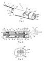
- Figure 1 is a perspective partially cutaway view of one presently preferred embodiment of the servovalve apparatus of the present invention.
- Figure 2 is vertical cross-sectional view of the embodiment of Figure 1 taken along lines 2-2 of Figure 1 which also includes a schematic illustration of an actuator device shown in broken lines.
- Figure 3 is a top, graphical view of the tip and receiving plate configuration used with the apparatus of Figures 1 and 2.
- servovalve 10 comprises a body 20 which may be formed of any suitable material. It is presently preferred that body 20 be formed of a soft magnetic material which is easy to machine and which has low hysteresis, such as, for example, silicon steel, leaded steel, or low carbon steel.
- body 20 could have a wide variety of different shapes and configurations, body 20 is illustrated herein as being substantially cylindrical. It is presently believed that the cylindrical configuration of body 20 facilitates the manufacture of servovalve 10, and is readily susceptible of being machined to accommodate the various component parts of servovalve 10, a described further below.
- End plate 30 may be formed of any suitable material, such as, for example, brass. End plate 30 is secured within the upstream end 20 of body 20 in some suitable manner such as by soldering or by means of an adhesive.
- End plate 30 is provided with a nipple 32, as shown, which may be attached to a source of pressurized fluid using a conventional fluid tube (not shown).
- An O-ring 33 preferably surrounds nipple 32 in a suitable groove to assist in sealing nipple 32 to the fluid tube.
- end plate 30 is provided with a spindle 34.
- Spindle 34 and nipple 32 may advantageously be formed as an integral part of end plate 30.
- nipple 32, end plate 30, and spindle 34 each have a bore therethrough which combine to form a substantially uniform, longitudinal passageway, the purpose of which will become more readily apparent from the discussion which follows.
- a mandrel 40 is provided on spindle 34 of end plate 30.
- Mandrel 40 may be formed of any suitable material such as, for example, steel, and could be formed as an integral part of end plate 30 or as a separate element.
- a downstream end disk 41 of the mandrel is made of a non-magnetic material such as aluminum, plastic, etc. The mandrel 40 will be further discussed hereafter.
- a suitable electrical conductor is wound around mandrel 40 so as to form a conductive coil.
- Any suitable electrical conductor may be used, such as, for example, # 30 copper magnet wire.
- the ends of wire 42 are then connected to suitable insulated wires 16 which pass out of body 20 through a suitable opening in end plate 30.
- wires 16 may be provided with some type of connector plug 18 for connecting wires 16 (and thus conductive coil 42) to a suitable source of electric current.
- a flexible conduit 60 passes through the central bore of end plate 30 and the central bore of the mandrel 40.
- the upstream end 62 of conduit 60 is secured within end plate 30 in some appropriate manner, such as, for example, by means of a conventional bushing 63.
- Conduit 60 may be formed of any suitable material, such as, for example, steel.
- An armature 64 is secured to conduit 60 so as to lie adjacent mandrel 40.
- Armature 64 may, for example, be formed of steel and may be slidable secured on conduit 40 by friction or a suitable adhesive.
- Armature 64 may have virtually any suitable geometric configuration.
- armature 64 may be a substantially rectangular member as best seen in Figure 1. It is presently preferred that a portion of armature 64 near mandrel 40 be diametrally enlarged, as shown in Figures 1 and 2. It is believed that the diametrally enlarged portion of armature 64 will assist the armature in conducting the magnetic induction current necessary for the proper operation of servovalve 10, as described in more detail below.
- Magnets 72 and 73 are positioned on opposite sides of armature 64, as shown in Figure 2. Magnets 72 and 73 may, for example, be secured to body 20 by means of suitable magnet mounts 70. Significantly, one magnet 72 or 73 is configured and positioned such that it presents a north magnetic pole facing armature 64, while the other such magnet is configured and positioned so as to present a south magnetic pole facing armature 64. While magnets 72 and 73 could be formed of a wide variety of different materials, it is presently preferred that magnets 72 and 73 be formed of a rare earth metal material. It is believed that rare earth magnets facilitate making servovalve 10 small and lightweight due to their superior magnetic characteristics.
- conduit 60 The downstream end of conduit 60 is preferably provided with a tip 66 which may be formed of any suitable material, such as, for example, brass. Tip 66 is secured to conduit 60 in some suitable manner, such as by means of friction or by means of a suitable adhesive. Importantly, tip 66 is configured as a fluid orifice or orifices through which fluid may flow from conduit 60.
- the downstream end of body 20 is provided with a receiving plate 80 which may, for example, be formed of brass.
- Receiving plate 80 is secured within body 20 in some appropriate fashion, such as by means of solder or adhesive.
- Receiving plate 80 has one or more fluid channels or groups of fluid channels 84 and 86 formed therein which terminate in openings or groups of openings 85 and 87, respectively (see Figure 1).
- Channels 84 and 86 advantageously originate within and communicate with an arcuate or concave socket 82 which is formed in the surface of receiving plate 80 inside body 20.
- the radius of curvature of socket 82 is substantially equal to the radius of curvature of the arcuate pathway over which the downstream end of conduit 60 moves during flexure, for reasons which will become more fully apparent from the discussion which follows.
- Figure 3 shows a top, graphical view of an exemplary configuration for the receiving plate 80 and tip 66.
- the receiving plate 80 has two rows of three channels (or more) 85 and 87
- the tip 66 has one row of three channels or orifices 86 each positioned midway between a corresponding pair of channels 85 and 87 when the tip is in the nondeflected position.
- tip 66 and receiving plate 80 Although there will generally be some distance between tip 66 and receiving plate 80, it is preferable to minimize this distance in order to reduce the amount of fluid leakage from between tip 66 and receiving plate 80.
- the distance between tip 66 and receiving plate 80 is not so small, however, that substantial frictional forces between the tip 66 and receiving plate 80 are present or that a lubricating fluid must be used in servovalve 10.
- the distance between tip 66 and receiving plate 80 can also be maintained at a substantially constant minimal level during flexure of conduit 60.
- servovalve 10 When used in a fluid system, servovalve 10 is attached by means of nipple 32 to a source of pressurized fluid. The pressurized fluid then enters conduit 60 through nipple 32 and travels toward receiving plate 80.
- Conductive coil 42 is connected by means of wires 16 and plug 18 to a source of electricity. As electrical current flows through coil 42, a magnetic current is induced through the center of coil 42 in accordance with well-known principles of electromagnetism. Because of this induced magnetic current, armature 64 which is adjacent one end of coil 42 will be magnetized as either a north magnetic pole or a south magnetic pull depending upon the direction of the electrical current in coil 42. As a result, armature 64 will be magnetically attracted toward either magnet 72 or magnet 73, and conduit 60 will be deflected either upwardly or downwardly in Figure 2.
- the direction of the electrical current through coil 42 may cause armature 64 to be magnetized as a north magnetic pole.
- armature 64 will be magnetically repelled from magnet 72 and magnetically attracted toward magnet 73.
- conduit 60 will be deflected downwardly in Figure 2.
- Conduit 60 could, of course, also be deflected upwardly in Figure 2 in a similar fashion by simply reversing the direction of the electrical current in coil 42.
- conduit 60 is deflected upwardly in Figure 2, fluid will flow through conduit 60 and through tip 66 into fluid channels 84.
- conduit 60 is deflected downwardly in Figure 2
- fluid will flow through conduit 60 and through tip 66 into channels 86.
- the flow of fluid into fluid channels 84 and 86 may be selectively controlled by simply controlling the direction of the electrical current in coil 42 which determines the direction conduit 60 is deflected.
- receiving plate 80 with a concave socket 82 which has a radius of curvature substantially equal to the radius of curvature of the pathway over which the downstream end of conduit 60 moves, a relatively close tolerance can be maintained between tip 66 and concave socket 82.
- the flow of fluid through conduit 60 can be virtually stopped by positioning conduit 60 in the nondeflected position, as illustrated in Figure 2, such that the orifice formed by tip 66 lies between fluid channels 84 and 86. While some fluid leakage can still be expected, the fluid leakage will be minimal as compared with prior art jet pipe valves.
- the performance of servovalve 10 can approach that of conventional spool valves while being much less expensive and much easier to manufacture and maintain.
- an appropriate filter may be provided around tip 66.
- a conventional porous metal material may be provided around tip 66 to act as a filter for any magnetized particles in the fluid.
- a series of baffles 92 may be provided around tip 66, as shown in Figure 2, and magnetic filters 93 may be positioned therebetween. As magnetized particles travel between baffles 92, magnetic filters 93 will trap such particles and prevent them from coming into contact with magnets 72 and 73.
- servovalve 10 may be connected to a suitable actuator 12, if desired.
- the pressurized fluid can be directed through channel 14 so as to cause extension of piston rod 13 of actuator 12.
- Fluid could thereafter be directed through channel 86 in receiving plate 80 to channel 15 which would cause piston rod 13 to be retracted.
- an actuator 12 may be connected directly to servovalve 10 by means of a suitable sleeve (not shown).
- a suitable sleeve (not shown).
- an O-ring 26 may be provided around body 20, as shown.
- the present invention provides a servovalve apparatus which can readily be used with high fluid flow rates and which can provide relatively high power output but which does not require the very tight tolerances of many prior art valve devices. It has, for example, been found that the servovalve apparatus of the present invention may easily be used with fluid flow rates within the range of from approximately one gallon per minute to approximately four gallons per minute. This is 10 to 40 times greater than the fluid flow rates typically used with conventional jet pipe valves.
- the physical configuration of the servovalve apparatus of the present invention also makes it possible to construct the servovalve apparatus much smaller than many conventional valves.
- the small size and relatively light weight of the servovalve apparatus is also achieved in part due to the use of rare earth magnets within the servovalve apparatus.
Landscapes
- Physics & Mathematics (AREA)
- General Physics & Mathematics (AREA)
- Engineering & Computer Science (AREA)
- Automation & Control Theory (AREA)
- Servomotors (AREA)
- Magnetically Actuated Valves (AREA)
- Details Of Valves (AREA)
- Electrically Driven Valve-Operating Means (AREA)
Applications Claiming Priority (2)
| Application Number | Priority Date | Filing Date | Title |
|---|---|---|---|
| US472701 | 1990-01-31 | ||
| US07/472,701 US5005600A (en) | 1990-01-31 | 1990-01-31 | Servovalve apparatus for use in fluid systems |
Publications (2)
| Publication Number | Publication Date |
|---|---|
| EP0440201A1 true EP0440201A1 (de) | 1991-08-07 |
| EP0440201B1 EP0440201B1 (de) | 1995-09-06 |
Family
ID=23876598
Family Applications (1)
| Application Number | Title | Priority Date | Filing Date |
|---|---|---|---|
| EP91101216A Expired - Lifetime EP0440201B1 (de) | 1990-01-31 | 1991-01-30 | Servoventil gebraucht in Druckmittelanlagen |
Country Status (7)
| Country | Link |
|---|---|
| US (1) | US5005600A (de) |
| EP (1) | EP0440201B1 (de) |
| JP (1) | JP3034035B2 (de) |
| AT (1) | ATE127574T1 (de) |
| CA (1) | CA2035074A1 (de) |
| DE (1) | DE69112654T2 (de) |
| WO (1) | WO1991011762A1 (de) |
Families Citing this family (3)
| Publication number | Priority date | Publication date | Assignee | Title |
|---|---|---|---|---|
| US5088383A (en) * | 1990-01-22 | 1992-02-18 | Woodward Governor Company | Multiplexed hydraulic control system with multiplexing valve having planar port array |
| DE50303266D1 (de) * | 2002-02-19 | 2006-06-14 | Schrott Harald | Bistabiles elektromagnetisches Ventil |
| DE10216687A1 (de) * | 2002-02-19 | 2003-08-28 | Aweco Appliance Sys Gmbh & Co | Bistabiles elektromagnetisches Ventil |
Citations (3)
| Publication number | Priority date | Publication date | Assignee | Title |
|---|---|---|---|---|
| US2858849A (en) * | 1955-02-28 | 1958-11-04 | Gen Controls Co | Multi-positional control valve |
| US2990839A (en) * | 1955-12-22 | 1961-07-04 | Gen Controls Co | Control device using magnetizable vibratory conduit |
| FR2390606A1 (fr) * | 1977-05-13 | 1978-12-08 | Honeywell Inc | Vanne pilote actionnee magnetiquement |
Family Cites Families (3)
| Publication number | Priority date | Publication date | Assignee | Title |
|---|---|---|---|---|
| US3011505A (en) * | 1957-02-08 | 1961-12-05 | Askania Regulator Co | Ejector for use in a jet-type hydraulic relay regulator |
| US3081787A (en) * | 1961-07-13 | 1963-03-19 | Pneumo Dynamics Corp | Hydraulic control valve |
| US4291716A (en) | 1977-05-13 | 1981-09-29 | Honeywell Inc. | Pilot stage valve |
-
1990
- 1990-01-31 US US07/472,701 patent/US5005600A/en not_active Expired - Lifetime
-
1991
- 1991-01-28 CA CA 2035074 patent/CA2035074A1/en not_active Abandoned
- 1991-01-30 DE DE69112654T patent/DE69112654T2/de not_active Expired - Fee Related
- 1991-01-30 WO PCT/US1991/000667 patent/WO1991011762A1/en not_active Ceased
- 1991-01-30 AT AT91101216T patent/ATE127574T1/de active
- 1991-01-30 EP EP91101216A patent/EP0440201B1/de not_active Expired - Lifetime
- 1991-01-30 JP JP50878991A patent/JP3034035B2/ja not_active Expired - Lifetime
Patent Citations (3)
| Publication number | Priority date | Publication date | Assignee | Title |
|---|---|---|---|---|
| US2858849A (en) * | 1955-02-28 | 1958-11-04 | Gen Controls Co | Multi-positional control valve |
| US2990839A (en) * | 1955-12-22 | 1961-07-04 | Gen Controls Co | Control device using magnetizable vibratory conduit |
| FR2390606A1 (fr) * | 1977-05-13 | 1978-12-08 | Honeywell Inc | Vanne pilote actionnee magnetiquement |
Also Published As
| Publication number | Publication date |
|---|---|
| CA2035074A1 (en) | 1991-08-01 |
| DE69112654D1 (de) | 1995-10-12 |
| WO1991011762A1 (en) | 1991-08-08 |
| EP0440201B1 (de) | 1995-09-06 |
| JPH04506699A (ja) | 1992-11-19 |
| ATE127574T1 (de) | 1995-09-15 |
| US5005600A (en) | 1991-04-09 |
| DE69112654T2 (de) | 1996-02-01 |
| JP3034035B2 (ja) | 2000-04-17 |
Similar Documents
| Publication | Publication Date | Title |
|---|---|---|
| US5133379A (en) | Servovalve apparatus for use in fluid systems | |
| EP0392784B1 (de) | Elektromagnetisches Ventil mit Verwendung eines permanenten Magneten | |
| US4848721A (en) | Hydraulic valve with integrated solenoid | |
| US4481389A (en) | Magnetic control device | |
| EP0672224A4 (de) | Magnetorheologisches ventil und vorrichtungen mit magnettorheologischen elementen. | |
| EP0140048A2 (de) | Elektrisch gesteuertes Druckaufnehmerventil | |
| US5734310A (en) | Magnetic latching solenoid assembly | |
| KR20190045866A (ko) | 래칭 공압식 제어 밸브 | |
| JPH01316585A (ja) | 可変フォースモータ及びその可変フォースモータを備えた電磁ソレノイド弁 | |
| US4464977A (en) | Fluid pressure device | |
| US5005600A (en) | Servovalve apparatus for use in fluid systems | |
| EP0481184A1 (de) | Elektromagnetisch gesteuertes Flüssigkeitskontrollventil | |
| EP0440194B1 (de) | Verbessertes Servoventil gebraucht in Druckmittelanlagen | |
| CA1129528A (en) | Electrically controlled proportional valve | |
| JP3426160B2 (ja) | 流量調節弁 | |
| US5067512A (en) | Servovalve apparatus for use in fluid systems | |
| CN110036227B (zh) | 阀装置 | |
| US5855228A (en) | Control valve assembly | |
| US20140001385A1 (en) | Adjustable Solenoid-Operated Directional Valve | |
| EP0571128A1 (de) | Motor mit Temperaturkompensation | |
| US11313487B2 (en) | Solenoid valve | |
| GB2124799A (en) | Electro-hydraulic servo valve | |
| GB2096283A (en) | Electro-fluid control device | |
| US3446472A (en) | Electrically operated fluid flow control devices | |
| RU2103720C1 (ru) | Электромагнитный регулятор давления |
Legal Events
| Date | Code | Title | Description |
|---|---|---|---|
| PUAI | Public reference made under article 153(3) epc to a published international application that has entered the european phase |
Free format text: ORIGINAL CODE: 0009012 |
|
| AK | Designated contracting states |
Kind code of ref document: A1 Designated state(s): AT BE CH DE DK ES FR GB GR IT LI NL SE |
|
| 17P | Request for examination filed |
Effective date: 19920205 |
|
| 17Q | First examination report despatched |
Effective date: 19930722 |
|
| GRAA | (expected) grant |
Free format text: ORIGINAL CODE: 0009210 |
|
| AK | Designated contracting states |
Kind code of ref document: B1 Designated state(s): AT BE CH DE DK ES FR GB GR IT LI NL SE |
|
| PG25 | Lapsed in a contracting state [announced via postgrant information from national office to epo] |
Ref country code: IT Free format text: LAPSE BECAUSE OF FAILURE TO SUBMIT A TRANSLATION OF THE DESCRIPTION OR TO PAY THE FEE WITHIN THE PRESCRIBED TIME-LIMIT;WARNING: LAPSES OF ITALIAN PATENTS WITH EFFECTIVE DATE BEFORE 2007 MAY HAVE OCCURRED AT ANY TIME BEFORE 2007. THE CORRECT EFFECTIVE DATE MAY BE DIFFERENT FROM THE ONE RECORDED. Effective date: 19950906 Ref country code: ES Free format text: THE PATENT HAS BEEN ANNULLED BY A DECISION OF A NATIONAL AUTHORITY Effective date: 19950906 Ref country code: DK Effective date: 19950906 Ref country code: GR Free format text: LAPSE BECAUSE OF FAILURE TO SUBMIT A TRANSLATION OF THE DESCRIPTION OR TO PAY THE FEE WITHIN THE PRESCRIBED TIME-LIMIT Effective date: 19950906 Ref country code: NL Free format text: LAPSE BECAUSE OF FAILURE TO SUBMIT A TRANSLATION OF THE DESCRIPTION OR TO PAY THE FEE WITHIN THE PRESCRIBED TIME-LIMIT Effective date: 19950906 Ref country code: AT Effective date: 19950906 |
|
| REF | Corresponds to: |
Ref document number: 127574 Country of ref document: AT Date of ref document: 19950915 Kind code of ref document: T |
|
| REF | Corresponds to: |
Ref document number: 69112654 Country of ref document: DE Date of ref document: 19951012 |
|
| PG25 | Lapsed in a contracting state [announced via postgrant information from national office to epo] |
Ref country code: SE Effective date: 19951206 |
|
| ET | Fr: translation filed | ||
| NLV1 | Nl: lapsed or annulled due to failure to fulfill the requirements of art. 29p and 29m of the patents act | ||
| PLBE | No opposition filed within time limit |
Free format text: ORIGINAL CODE: 0009261 |
|
| STAA | Information on the status of an ep patent application or granted ep patent |
Free format text: STATUS: NO OPPOSITION FILED WITHIN TIME LIMIT |
|
| 26N | No opposition filed | ||
| PGFP | Annual fee paid to national office [announced via postgrant information from national office to epo] |
Ref country code: FR Payment date: 19980129 Year of fee payment: 8 Ref country code: GB Payment date: 19980129 Year of fee payment: 8 |
|
| PGFP | Annual fee paid to national office [announced via postgrant information from national office to epo] |
Ref country code: BE Payment date: 19980130 Year of fee payment: 8 |
|
| PGFP | Annual fee paid to national office [announced via postgrant information from national office to epo] |
Ref country code: CH Payment date: 19980219 Year of fee payment: 8 |
|
| PGFP | Annual fee paid to national office [announced via postgrant information from national office to epo] |
Ref country code: DE Payment date: 19980225 Year of fee payment: 8 |
|
| PG25 | Lapsed in a contracting state [announced via postgrant information from national office to epo] |
Ref country code: GB Free format text: LAPSE BECAUSE OF NON-PAYMENT OF DUE FEES Effective date: 19990130 |
|
| PG25 | Lapsed in a contracting state [announced via postgrant information from national office to epo] |
Ref country code: LI Free format text: LAPSE BECAUSE OF NON-PAYMENT OF DUE FEES Effective date: 19990131 Ref country code: CH Free format text: LAPSE BECAUSE OF NON-PAYMENT OF DUE FEES Effective date: 19990131 Ref country code: BE Free format text: LAPSE BECAUSE OF NON-PAYMENT OF DUE FEES Effective date: 19990131 |
|
| BERE | Be: lapsed |
Owner name: SARCOS GROUP Effective date: 19990131 |
|
| REG | Reference to a national code |
Ref country code: CH Ref legal event code: PL |
|
| GBPC | Gb: european patent ceased through non-payment of renewal fee |
Effective date: 19990130 |
|
| PG25 | Lapsed in a contracting state [announced via postgrant information from national office to epo] |
Ref country code: FR Free format text: LAPSE BECAUSE OF NON-PAYMENT OF DUE FEES Effective date: 19990930 |
|
| PG25 | Lapsed in a contracting state [announced via postgrant information from national office to epo] |
Ref country code: DE Free format text: LAPSE BECAUSE OF NON-PAYMENT OF DUE FEES Effective date: 19991103 |
|
| REG | Reference to a national code |
Ref country code: FR Ref legal event code: ST |