EP0440241A2 - Photographische Filmkassette - Google Patents
Photographische Filmkassette Download PDFInfo
- Publication number
- EP0440241A2 EP0440241A2 EP91101310A EP91101310A EP0440241A2 EP 0440241 A2 EP0440241 A2 EP 0440241A2 EP 91101310 A EP91101310 A EP 91101310A EP 91101310 A EP91101310 A EP 91101310A EP 0440241 A2 EP0440241 A2 EP 0440241A2
- Authority
- EP
- European Patent Office
- Prior art keywords
- film
- cassette
- light
- passageway
- fabric
- Prior art date
- Legal status (The legal status is an assumption and is not a legal conclusion. Google has not performed a legal analysis and makes no representation as to the accuracy of the status listed.)
- Granted
Links
Images




Classifications
-
- G—PHYSICS
- G03—PHOTOGRAPHY; CINEMATOGRAPHY; ANALOGOUS TECHNIQUES USING WAVES OTHER THAN OPTICAL WAVES; ELECTROGRAPHY; HOLOGRAPHY
- G03B—APPARATUS OR ARRANGEMENTS FOR TAKING PHOTOGRAPHS OR FOR PROJECTING OR VIEWING THEM; APPARATUS OR ARRANGEMENTS EMPLOYING ANALOGOUS TECHNIQUES USING WAVES OTHER THAN OPTICAL WAVES; ACCESSORIES THEREFOR
- G03B17/00—Details of cameras or camera bodies; Accessories therefor
- G03B17/28—Locating light-sensitive material within camera
- G03B17/30—Locating spools or other rotatable holders of coiled film
-
- G—PHYSICS
- G03—PHOTOGRAPHY; CINEMATOGRAPHY; ANALOGOUS TECHNIQUES USING WAVES OTHER THAN OPTICAL WAVES; ELECTROGRAPHY; HOLOGRAPHY
- G03B—APPARATUS OR ARRANGEMENTS FOR TAKING PHOTOGRAPHS OR FOR PROJECTING OR VIEWING THEM; APPARATUS OR ARRANGEMENTS EMPLOYING ANALOGOUS TECHNIQUES USING WAVES OTHER THAN OPTICAL WAVES; ACCESSORIES THEREFOR
- G03B2217/00—Details of cameras or camera bodies; Accessories therefor
- G03B2217/26—Holders for containing light-sensitive material and adapted to be inserted within the camera
- G03B2217/265—Details of light-proofing
-
- G—PHYSICS
- G03—PHOTOGRAPHY; CINEMATOGRAPHY; ANALOGOUS TECHNIQUES USING WAVES OTHER THAN OPTICAL WAVES; ELECTROGRAPHY; HOLOGRAPHY
- G03B—APPARATUS OR ARRANGEMENTS FOR TAKING PHOTOGRAPHS OR FOR PROJECTING OR VIEWING THEM; APPARATUS OR ARRANGEMENTS EMPLOYING ANALOGOUS TECHNIQUES USING WAVES OTHER THAN OPTICAL WAVES; ACCESSORIES THEREFOR
- G03B2217/00—Details of cameras or camera bodies; Accessories therefor
- G03B2217/26—Holders for containing light-sensitive material and adapted to be inserted within the camera
- G03B2217/266—Thrust-type cartridges
Definitions
- the present invention relates a photographic film cassette, more particularly to a construction of a film passageway through which film is advanced from the film cassette.
- a photographic film cassette for containing a photographic filmstrip (hereinafter referred to as "film") of 135-type (i.e. 35 mm in width) is the most prevalent of various film cassettes.
- This film cassette consists of a light-tight cylindrical cassette body having a film passageway, a spool rotatably contained in the cassette body, and the film coiled around the spool.
- Light trapping fabric (generally called “plush” in the field of photography) is attached to the inner surfaces of the film passageway for trapping light entering the cassette body through a film passage mouth.
- this light trapping fabric fabric constituted of woven fabric and pile threads woven therein as described in Japanese Utility Model Publication 37-21388; fabric constituted of knitted fabric and pile threads woven therein as described in Japanese Utility Model Publication 61-34526; pile threads planted on the film passageway as disclosed in Japanese Utility Model Publication 37-4453, and Japanese Patent Laid-Open Publications 53-105222 and 57-190947; and fabric constituted of non-woven fabric as disclosed in Japanese Utility Model Laid-Open Publication 51-127737.
- a film leader of the film coiled in a roll is in a state protruded from the film passage mouth.
- a film cassette with the whole of the roll film contained in the cassette body up to a leading end of the film has been recently proposed, in which film cassette a rotation of the spool causes the film to advance to the outside of the cassette body toward a film take-up chamber in a camera so as to wind the film on a take-up spool in the film take-up chamber, as disclosed in U.S.P. 4,832,275 and 4,834,306.
- a film cassette having a cassette body formed out of plastics, which has been used recently.
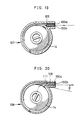
- Fig. 28 illustrating an important portion of this film cassette, the opposite lateral sides of a film passageway in a cassette body are defined by both lateral walls 140 and 141, between which light trapping fabric 142 is attached to both inner surfaces of the film passageway. If the precision in attachment of the light trapping fabric is low as to the position, gaps might appear between the lateral ends of the light trapping fabric 142 and the lateral walls 140 and 141. There is a problem is that fogging might be generated on photographic film 14 when external light is incident on the inside of the cassette body 56 through the gaps.
- a film cassette has been proposed for solving this problem as described in Japanese Patent Laid-Open Publication 57-190948, in which extra fabric for trapping light is attached to both lateral walls of the film passageway.
- the light trapping fabric is attached to the film passageway so as to press the film between both pieces thereof in a self-advance film cassette described above, the light trapping fabric is considerably resistant to advancing the film. There are problems in this light trapping fabric which might bend the film in the cassette body, stop the film from advancing, and damage surfaces of the film.
- the pile threads of the above-described light trapping fabric occupy a larger space at their tips but a smaller space at their bottoms, because they are bunched at their bottoms. Light is trapped reliably at the middle between the upper and lower surfaces of the film passageway, but incompletely in the vicinity of the upper and lower surfaces. In Fig. 29, external light entering the inner surfaces of the film passageway might be incident on the outermost turn of the film 14 without being trapped by the light trapping fabric 142.
- a film cassette as disclosed in Japanese Patent Laid-Open Publication 57-190948 has a problem of too high cost, because two different types of light trapping fabric are necessary.
- a photographic film cassette comprises: first and second light trapping members provided each on upper and lower surfaces of the film passageway for trapping light; and means for guiding the film leader to be close to a position defined between the first and second light trapping members when the film leader advances passing between the first and second light trapping members.
- first fabric having pile threads is disposed on an upper surface of the film passageway for contact with an outside surface in a coiled state of the film, while second fabric having pile threads is disposed on an lower surface of the film passageway for contact with an inside surface in a coiled state of the film.
- a ridge extended portion extends from a ridge formed on an inner surface of the cassette body in order to prevent the film from loosening toward the film passage mouth along the upper surface.
- resilient members are each disposed on upper and lower surfaces of the film passageway, while pile threads are planted on a surface of the resilient members.
- the film cassette further comprises the inclined surfaces which have an inclination such that the width of the said passageway increases in the direction toward the inside of the film cassette until the steps formed on both inner surfaces.
- the film cassette further comprises means for shielding light in passage through gaps between bottoms of the pile threads.
- a narrow of the film passageway formed at the film passage mouth According to another preferred embodiment, a light-shielding member projects from the lower surface obliquely toward the inside of the cassette body.
- a recess is formed on the upper surface in order to attach the first fabric to a position retracted from the film passageway, while the lower surface is arranged to have such a short distance to the upper surface as corresponds to a depth of the recess in order to reduce an angle at which light passed through gaps between bottoms of the pile threads impinges on the outer turns of the coiled film.
- stepped portions are each formed on the upper and lower surfaces.
- steps are formed on lateral walls of the film passageway facing on lateral edges of the film so as to widen the film passageway in the vicinity of the film passage mouth in order to shield light incident on gaps between the lateral walls and the fabrics.
- the film can be guided smoothly for a film advance without resistance of light trapping fabric.
- the film can also be shielded reliably from light in passage through gaps involved in the light trapping fabric at a low cost without high friction between the film and the light trapping fabric during the film advance.
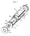
- the film cassette 10 consists of a cassette shell 12, a spool 16 with the photographic film 14 coiled thereabout, and cassette caps 18 and 20.
- the cassette shell 12 for containing the film 14 e.g. negative film coiled around the spool 16 has two annular ridges 22 and 24 formed on its inner surface in order to reduce friction between the film 14 and the inner surface of the cassette shell 12.
- Light trapping fabric 28 is attached on the upper and lower surface of a film passageway 26 in the cassette shell 12, in order to prevent light from entering the cassette shell 12.
- the light trapping fabric 28 is constituted of black-dyed velvet having rayon ground fabric with warp thread of 75 deniers and weft thread of 150 deniers, and nylon pile threads of 75 deniers.
- Other material may also be used for the ground fabric and the pile threads: synthetic fibers such as nylon, acrylic fibers, polyester, vinylon, vinyl chloride, vinylidene copolymer, polypropylene and polyethylene polycarbonate; and natural or regenerated fibers such as rayon, cupro-ammonium rayon, acetate, cotton and silk.
- the light trapping fabric 28 may also be attached with sealer adhesive agent used for both the sealer and the adhesive agent, or double-coated adhesive tape, or by spot welding in the case of a plastic cassette shell.
- the spool 16 has flanges 30a and 30b for supporting the film between both ends of the spool 16, and is to be rotated for advancing the leading end 14a of the film 14 to the outside of the cassette shell 12.
- Bearing openings 18a and 20a are formed each in the cassette caps 18 and 20 for receiving and supporting a spool shaft 16a.
- the light trapping fabric 28 consists of upper and lower fabric pieces 28a and 28b attached each to the upper and lower surfaces of the film passageway 26.
- the tips of the pile threads of each of the fabric pieces 28a and 28b actually project among the pile threads of the opposite fabric piece, although the fabric pieces 28a and 28b are illustrated separate at the center of the film passageway 26 for the purpose of understanding.
- the ridge 22 is extended to locate a lower end 22a of the ridge 22 at the innermost position of the film passageway 26, and an upper end 22b of the ridge 22 at the middle of the film passageway 26 outside its innermost position.
- the upper ridge end 22b is formed to be in contact with the upper surface of the film 14 so as to guide the film 14 to the middle between the fabric pieces 28a and 28b at the time of advancing the film 14.
- the projecting degree of the upper ridge end 22b such that the film 14 advances against the lower fabric piece 28b at a position higher than the position of 1/4 as high as the length H of the pile threads with reference to the upper surface of the ground fabric of the lower fabric piece 28b as illustrated in Fig. 4. This is because the advance position higher than H/4 can reduce to a comparative extent the resistance received by the film 14 upon advancing against the light trapping fabric 28.
- the ridge 24 has the same construction as the ridge 22 described as above.
- FIG. 5 An upper end of a ridge 33 is elongated until the innermost position of the film passageway 26.
- An upper fabric piece of a light trapping fabric 35 is also elongated in the direction to the inside of the cassette shell 12 to be in contact with the upper end of the ridge 33.
- a film cassette 36 illustrated in Fig. 6 has a ridge 37 the same as a conventional film cassette, such that its upper end is retracted internally from the innermost position of the film passageway 26.
- a film cassette 40 illustrated in Fig. 7 is the same as the film cassette 36 in Fig. 6, except that the film passageway 26 is shortened.
- a film cassette 41 illustrated in Fig. 8 has the same ridge 33 as the film cassette 32 in Fig. 5, and light trapping resilient members 44a and 44b disposed on the upper and lower surfaces of the film passageway 26. Pile threads 45 of a short length are planted on the surfaces of the resilient members 44a and 44b by a static charge.
- the film 14 during an advance is held between the resilient members 44a and 44b with an appropriate force based on their resilience. Even in contact with the resilient members 44a and 44b, the leading end 14a is guided to the outside of the film passageway 26 by the resilience of the resilient members 44a and 44b.
- Figs. 1 to 8 are 135 type having been widespread in use. Because the above-described light trapping fabric can pass the film smoothly therethrough with a reliable light-trapping function, it is much effective to apply it to a self-advancing film cassette for advancing a film leader through a film passageway by rotating the spool. The resistance of light trapping fabric must be as small as possible in a self-advancing film cassette before the film leader can be advanced from the film passageway.
- Figs. 9 to 14 illustrates embodiments of self-advancing film cassettes with such light trapping fabric attached to a film passageway as is the main part of the present invention. Elements substantially similar in these drawings are designated by the same reference numerals.
- a self-advancing film cassette 55 illustrated in Fig. 9 has the two annular ridges 22 and 24 formed in the inner surface of a cassette shell for receiving film wound in a roll in order to transmit rotation of a spool reliably to the film roll.
- the film cassette 55 consists of the cassette body 56 and the film 14 contained therein in a coiled state.
- the cassette body 56 includes two shell halves 58 and 59, and a spool 16 rotatably contained therein.
- the shell halves 58 and 59 are made from plastics and attached together containing the spool 16 with the film 14 coiled thereabout.
- the ridges 22 and 24 are formed integratedly with the shell halves 58 and 59 on the inner surface along the circumferential direction.
- the ridges 22 and 24 are in contact with the outermost turn of the film 14 to prevent the film roll from loosening.
- the ridges 22 and 24 have separation claws 63 and 64 for separating the leading end 14a of the film 14 from the film roll.
- the film roll is rotated together with the spool 16 when the spool 16 is rotated in the unwinding direction.
- the film leading end 14a is separated by the separation claws 63 and 64 and advanced to the outside of the cassette body 56 through the film passageway 26. It is noted that the light trapping fabric as described above is attached to the film passageway 26, though not illustrated in Fig. 9.
- a self-advancing film cassette 66 illustrated in Fig. 10 has a pair of flanges of a spool for nipping the film roll so as to transmit rotation of the spool reliably to the film roll.
- a pair of arcuate ridges 67 and 68 are formed integratedly with the shell half 58 on both opposite inner sides. The ridges 67 and 68 abut respectively the flanges 30b and 30a of the spool 16 to bend them inwardly.
- the deformed flanges 67 and 68 support both end faces of the film roll to clamp the film 14. The rotation of the spool 16 is thus transmitted to the film roll to protrude the leading end 14a out of the cassette body 56.
- a self-advancing film cassette 71 illustrated in Fig. 11 has two rings for preventing a film roll from loosening.
- a pair of grooves 72 and 73 are formed on the inner surfaces of the shell halves 58 and 59 in an oblique direction relative to the direction vertical to the spool 16. Rings 74 and 75 are rotatably inserted in the grooves 72 and 73 for abutting and pressing the outermost turn of the film roll in order to prevent the film 14 from loosening.
- a self-advancing film cassette 76 illustrated in Fig. 12 has rims 77 and 78 projecting inwardly along the peripheral edges of the flanges 30a and 30b.
- the rims 77 and 78 abut and position the edge of the outermost turn of the film roll to prevent the film 14 from loosening.
- the rims 77 and 78 partly abut the sides of the separation claws 79 and 80 to be bent outwardly.
- the film roll is released from the rims 77 and 78 at the position close to the film passageway 26.
- the leading end 14a is thus separated from the film roll by the separation claws 79 and 80, and smoothly advanced through the film passageway 26 without being prevented by the rims 77 and 78.
- a self-advancing film cassette 82 illustrated in Figs. 13 and 14 has flanges which clamp the film roll during a film advance, and are released from the film roll while winding the film 14.
- a spool 83 consists of two spool pieces 84 and 85.
- a shaft 84a of the spool piece 84 has a cylindrical recess formed on the tip, in which a shaft 85a of the spool piece 85 is slidably fitted.
- a ridge 86 is formed on the shaft 84a thereabout and rotatably fitted in a circular groove formed on a shaft bearing of the shell halves 58 and 59.
- the bottom of the cylindrical recess of the shaft 84a has an inclined surface 87.
- the tip of the shaft 85a of the spool piece 85 is also inclined to be fitted on the inclined surface 87.
- the spool pieces 84 and 85 are provided with flanges 84b and 85b each integrated therewith for clamping both opposite sides of the film roll while advancing the film 14.
- the ridges 22 and 24 are formed on the shell halves 58 and 59 for receiving the outermost turn of the film roll in order to prevent the film roll from loosening.
- the spool piece 85 When the spool piece 84 is rotated in the unwinding direction, the spool piece 85 is immediately slid to the spool piece 84 according to a cam mechanism (not shown) for linking the spool pieces 84 and 85.
- the film roll is clamped between both flanges 84b and 85b as is illustrated in Fig. 14.
- the spool pieces 84 and 85 are rotated together so as to rotate the film roll integratedly without loosening.
- the leading end 14a is reliably advanced outside the cassette body 56 through the film passageway 26.
- the cam mechanism slides the spool piece 85 outwardly to enlarge the distance between the flanges 84b and 85b. This distance becomes larger than the width of the film 14 so that the film 14 can be rewound on the shaft 84a.
- the results of experiments are next described as to the above-described embodiments.
- the experiments were conducted on the torque applied to the spool shaft 16a upon entering the leading end 14a in the film passageway 26 while rotating the spool shaft 16a from a state with the leading end 14a of the film all wound in the cassette body 12.
- the applied torque was measured by a torquemeter to determine the resistance applied to the film 14.
- the maximum torque applied to the spool shaft 16a was 135 g ⁇ cm in the embodiment illustrated in Fig. 2, 155 g ⁇ cm in that illustrated in Fig. 5, 150 g ⁇ cm in that illustrated in Fig. 6, 145 g ⁇ cm in that illustrated in Fig. 7, and 132 g ⁇ cm in that illustrated in Fig. 8. Because it has been known from prior experiments that the film 14 can smoothly be advanced when the torque applied to the spool shaft 16a is below 200 g ⁇ cm, the results of the above experiments show that the film 14 can be advanced smoothly from the film cassettes according to the present invention.
- Figs. 15 and 16 illustrating a film cassette 91 according to an embodiment for shielding the film from the light which would pass through the light trapping fabric
- elements the same as those illustrated in Fig. 9 are designated by the same reference numerals.
- the edges to be joined of the shell halves 58 and 59 are stepped edges 58a and 59a for preventing light from entering the inside of the cassette body 56 through the juncture between the shell halves 58 and 59.
- the circumference of the cassette body 56 is provided with a film passage mouth 97, inside which a film passageway 99 is formed for directing the film 14 to the film passage mouth 97.
- the upper and lower surfaces of the film passageway 99 are inclined surfaces 99a and 99b between which the interval is narrower at the film passage mouth 97 than in the inside.
- Light trapping fabric 100 having ground fabric 100a and pile threads 100b is attached on each of the inclined surfaces 99a and 99b.
- the tips of the pile threads 100b on each surface of the film passageway 99 touch the ground fabric 100a across the film passageway 99.
- Both annular ridges formed on the cassette body 56 presents the film 14 from loosening.
- Both ends of the ridge 22 are ridge ends 22a and 22c for guiding the leading end 14a to the film passageway 99.
- the separation claw 63 is formed on the ridge end 22a with its tip directed to the inside of the cassette body 56 in order to separate the leading end 14a from the outermost turn of the film 14.
- the leading end 14a is separated from the outermost turn of the film 14, and is guided to a position between upper and lower fabric pieces of the light trapping fabric 100 by the ridge ends 22a and 22c.
- the leading end 14a having been passed through the upper and lower fabric pieces is advanced to the outside of the cassette body 56 through the film passage mouth 97.
- the tips of the pile threads 100b on each surface of the film passageway 99 touch the ground fabric 100a across the film passageway 99.
- the gaps between the bottoms or roots of the pile threads 100b on each side are filled with the tips of the pile threads 100b of the fabric piece on the opposite side so as to reliably prevent external light from passing through the bottoms of the pile threads 100b.
- the inside of the cassette body 56 is completely shielded from external light, involving no fogging on the film 14.
- the leading end 14a passes through the ground fabric 100a while pushing the pile threads 100b. If the pile threads 100b were to be densely planted, the film 14 would not be smoothly advanced against an enlarged friction in contact between the film 14 and the light trapping fabric 100. In the present film cassette 91, however, the tips of the densely formed pile threads 100b close to the film passage mouth 97 are pushed out of the cassette body 56 while advancing the film 14, and moved to a wider space through the ground fabric 100a while rewinding the film 14. Therefore, the friction between the film 14 and the light trapping fabric 100 never be enlarged along the film passageway 99. The film 14 can be smoothly advanced.
- Various materials can be used as the light trapping fabric 100: pile fabrics such as velvet and plush, knitted fabrics having pile threads, and pile-fitted materials.
- projecting edges 58b and 59b formed on the shell halves 58 and 59 define stepped portions for rendering the interval of the film passage mouth 97 narrower than the width of a film passageway 104.
- the projecting degree of the projecting edges 58b and 59b is determined so as to project by a length of approximately 1 /4 of the length of the pile threads 100b over the surfaces of the ground fabric 100a.
- the projecting edges 58b and 59b have a function of stiffeners preventing the film passage mouth 97 from being deformed.
- the projecting edges 58b and 59b shield the film passageway 104 from parallel impinging external light entered through the bottoms of the pile threads 100b.
- the pile threads 100b completely shield parallel impinging external light directed to the film passageway 104 through the film passage mouth 97. No fogging is developed on the film 14 because the inside of the cassette body 56 is reliably shielded from the outside. Even when the leading end 14a is advanced between the projecting edges 58b and 59b, the film 14 is kept from being damaged under protection with the pile threads 100b pushed by the leading end 14a.
- the film cassette 107 has a light shielding member 105 formed at the innermost position of a film passageway 108 in parallel with the spool 16.
- the fogging of the film 14 might have been caused on a part of the film roll close to the innermost position of the film passageway 99, but can be reduced greatly in the film cassette 107 thus constructed, because the light shielding member 105 shields the film 14 from external light directed to the outermost turn of the film roll upon passing through the bottoms of the pile threads 100b on the lower side of the film passageway 108.
- Fig. 20 illustrating a film cassette 109 according to yet another embodiment
- the upper surface of a film passageway 111 is provided with a recess 106 formed thereon, where the upper piece of the light trapping fabric 100 is attached so that the ground fabric 100a is fitted in the recess 106.
- the construction of the film passageway 111 for retracting the upper fabric piece upward therefrom makes it possible to keep the interval of both sides of the ground fabric 100a the same as a conventional film cassette, and also to form the lower surface of the film passageway 111 in an upper position by a length corresponding to the thickness of the ground fabric 100a relative to a conventional film cassette.
- the light passed through the bottoms of the pile threads 100b on the lower side is incident on the outermost turn of the film 14 in a position higher by a length corresponding to the depth of the recess 106 than the film cassette illustrated in Fig. 29.
- the light impinges on the film 14 at a smaller angle ⁇ to the tangent of the outermost turn of the film 14, so that the fogging will be reduced on the film 14.
- the conventional film includes an antihalation coating of which the peak value of the light absorbing capacity is approximately 0.8. If the peak value of the light absorbing capacity is 1.6, then the amount of light can be reduced to 1/10 after passing through the antihalation coating.
- a film passageway 119 of the film cassette 118 has two steps 110 each on the upper and lower surfaces.
- the difference between the levels defined by the steps 110 is as long as the thickness of the ground fabric 100a plus 1/4 of the length of the pile threads 100b, in order to shield the inside of the cassette body 56 from external light upon passing through the bottoms of the pile threads 100b.
- the film cassette 123 has a single fabric piece as light trapping fabric 113 for shielding a film passageway 127 from light.
- a cassette body 124 consisting of a pair of shell halves 125 and 126 is formed small in diameter without a particular projection for the film passage mouth 97.
- the film passageway 127 has the step 110 formed on the upper surface, and two steps 112a and 112b formed on the lower surface.
- the light trapping fabric 113 attached to the upper side of the film passageway 127 consists of the ground fabric 100a and pile threads 113b longer than the above-described pile threads 100b. The tips of the pile threads 113b touch the lower surface of the film passageway 127 in the inner positions of narrow widths, but do not touch it in the outer position outside the step 112b.
- the external light passed through the bottoms of the pile threads 113b is prevented by the step 110 from entering the inside of the cassette body 124.
- the external light is reliably prevented by the pile threads 113b densely bent in the narrow inner space of the film passageway 127. It is noted that, though the pile threads 113b are dense in the narrow inner space of the film passageway 127, the force for advancing the film 14 does not need to be large in the film cassette 123 because the narrow inner space has a short length.
- a film passageway 129 of a film cassette 128 is provided with inclined surfaces 114 and 115 as its upper and lower surfaces for attaching the light trapping fabric 100 thereto.
- the inclined surfaces 114 and 115 has such an inclination that the width of the film passageway 129 increases in the direction toward the inside of the film cassette 128 until the steps formed on both inner surfaces. Therefore, the leading end 14a can be smoothly entered through the ground fabric 100a in the film cassette 128, as well as the bottoms of the pile threads 100b are reliably shielded from light at the film passage mouth 97.
- a film passageway 131 of the film cassette 130 has a step 116 formed on each of both lateral walls in order to enlarge the lateral width of the film passageway at the film passage mouth 97.
- a juncture 117 between shell halves 58 and 59 traverses the step 116.
- the juncture 117 to be engaged together has a construction of labyrinth constituted of lines forming angles.
- the step 116 prevents the external light from entering the film cassette 130 through the gaps between the light trapping fabric 100 and both lateral walls of the film passageway 131 as is illustrated in Fig. 26.
- the angularly formed juncture 117 to be engaged together may also be constructed such that a projection on the edge of the upper shell half 58 engages with a recess of the edge of the lower shell half 59 as is illustrated in Fig. 25B.
- the film passageway of the film cassette 132 has the two steps 110 on the upper and lower surfaces (see Fig. 21), the two steps 116 on both lateral walls (see Fig. 25A), and the light shielding member 105 on the innermost position close to the roll of film (see Fig. 18).
- the juncture traversing the steps 116 has a labyrinthian construction of lines forming angles.
- the light shielding structure thus constructed is preferably designed to have: 5 mm for the width A of the fabric fitting portion outside the steps 110; 1 mm for the height B of the steps 110; 1 mm for the height C of the steps 116; 3 mm for the length D of the light shielding member 105; 1.5 mm for the interval E between the lower of the steps 110 and the bottom of the light shielding member 105; and 30 degrees for an angle ⁇ formed along the juncture to be engaged.
- constructions for shielding the film from light have been described as applied in a film cassette for 35 mm roll film, these constructions may also be applied in other various plastic film cassettes such as a 110 cartridge and a film cassette without a mechanism for causing the film to be advanced by rotating the spool.
- any of the embodiments according to the present invention not only is applied in a film cassette for being loaded in a camera, but also may be applied in a container for containing any photographic film in the form of a filmstrip, e.g. film for computerized typesetting, light-sensitive resin film, and microfilm.
- a filmstrip e.g. film for computerized typesetting, light-sensitive resin film, and microfilm.
Landscapes
- Physics & Mathematics (AREA)
- General Physics & Mathematics (AREA)
- Photographic Developing Apparatuses (AREA)
Applications Claiming Priority (6)
| Application Number | Priority Date | Filing Date | Title |
|---|---|---|---|
| JP2024216A JP2672168B2 (ja) | 1990-02-02 | 1990-02-02 | 写真フイルムパトローネ |
| JP2421690 | 1990-02-02 | ||
| JP24216/90 | 1990-02-02 | ||
| JP2177972A JP2758486B2 (ja) | 1990-07-05 | 1990-07-05 | 写真フイルムカートリッジ |
| JP177972/90 | 1990-07-05 | ||
| JP17797290 | 1990-07-05 |
Publications (3)
| Publication Number | Publication Date |
|---|---|
| EP0440241A2 true EP0440241A2 (de) | 1991-08-07 |
| EP0440241A3 EP0440241A3 (en) | 1992-12-16 |
| EP0440241B1 EP0440241B1 (de) | 1999-09-01 |
Family
ID=26361705
Family Applications (1)
| Application Number | Title | Priority Date | Filing Date |
|---|---|---|---|
| EP91101310A Expired - Lifetime EP0440241B1 (de) | 1990-02-02 | 1991-01-31 | Photographische Filmkassette |
Country Status (3)
| Country | Link |
|---|---|
| US (1) | US5318238A (de) |
| EP (1) | EP0440241B1 (de) |
| DE (1) | DE69131559T2 (de) |
Cited By (3)
| Publication number | Priority date | Publication date | Assignee | Title |
|---|---|---|---|---|
| US5271983A (en) * | 1990-04-19 | 1993-12-21 | Fuji Photo Film Co., Ltd. | Structure of light-shielding cloth and film container using the same |
| US5368464A (en) * | 1992-12-31 | 1994-11-29 | Eastman Kodak Company | Ultrasonic apparatus for cutting and placing individual chips of light lock material |
| US5480501A (en) * | 1993-01-19 | 1996-01-02 | Eastman Kodak Company | Ultrasonic apparatus and method for placing individual chips of light lock material |
Families Citing this family (1)
| Publication number | Priority date | Publication date | Assignee | Title |
|---|---|---|---|---|
| US5820897A (en) * | 1995-07-27 | 1998-10-13 | Xerox Corporation | Apparatus for handling and dippling flexible belts using a blow molded polymer chucking device |
Family Cites Families (40)
| Publication number | Priority date | Publication date | Assignee | Title |
|---|---|---|---|---|
| US2364381A (en) * | 1942-01-14 | 1944-12-05 | Eastman Kodak Co | Roll holding camera |
| US2336278A (en) * | 1942-02-13 | 1943-12-07 | Eastman Kodak Co | Film winding apparatus |
| US2360255A (en) * | 1942-02-13 | 1944-10-10 | Eastman Kodak Co | Automatic film winding mechanism |
| US2521935A (en) * | 1946-12-17 | 1950-09-12 | Ex Cell O Corp | Stapling machine |
| US2552200A (en) * | 1947-02-20 | 1951-05-08 | Eastman Kodak Co | Light-tight photographic film cartridge |
| DE1007615B (de) * | 1954-11-12 | 1957-05-02 | Wolfen Filmfab Veb | Lichtschutzhuelse |
| US3128058A (en) * | 1961-12-27 | 1964-04-07 | Du Pont | Plastic casing for photographic film spools having light-absorbing baffles |
| US3467340A (en) * | 1966-11-01 | 1969-09-16 | Eastman Kodak Co | Apparatus for and method of feeding strip material |
| US3556435A (en) * | 1968-05-20 | 1971-01-19 | Eastman Kodak Co | Film-threading apparatus |
| US3797777A (en) * | 1970-04-08 | 1974-03-19 | Matsushita Electric Industrial Co Ltd | Tape reel and tape reel storing magazine |
| US3627229A (en) * | 1970-08-27 | 1971-12-14 | Eastman Kodak Co | Strip-feeding apparatus and method |
| US3627230A (en) * | 1970-08-27 | 1971-12-14 | Eastman Kodak Co | Apparatus for feeding strip material |
| US3677499A (en) * | 1971-01-29 | 1972-07-18 | Eastman Kodak Co | Apparatus for feeding strip material of different widths |
| US3945584A (en) * | 1973-05-16 | 1976-03-23 | Ilford Limited | Film cassettes |
| DE2516436B2 (de) * | 1975-04-15 | 1979-02-22 | Develop Dr. Eisbein Gmbh & Co, 7016 Gerlingen | Kopiergerät mit einer Magnetwalzen-Entwicklungseinrichtung und einer Fixiereinrichtung |
| JPS53105222A (en) * | 1977-02-25 | 1978-09-13 | Origin Electric | Ribbon for photographhfilm cartridge |
| DE2921379C3 (de) * | 1979-05-25 | 1982-01-14 | Geimuplast Peter Mundt Gmbh & Co Kg, 8105 Farchant | Rollfilmkassette aus Kunststoff |
| GB2072622A (en) * | 1980-04-02 | 1981-10-07 | Ciba Geigy Ag | Roll film cassette |
| DE3023819A1 (de) * | 1980-06-25 | 1982-01-21 | Agfa-Gevaert Ag, 5090 Leverkusen | Filmkassette fuer einen lichtempfindlichen filmstreifen |
| DE3110622A1 (de) * | 1981-03-18 | 1982-09-30 | Agfa-Gevaert Ag, 5090 Leverkusen | Filmpatrone und/oder zugehoerige kamera |
| DE3118210A1 (de) * | 1981-05-08 | 1982-12-02 | Agfa-Gevaert Ag, 5090 Leverkusen | Kapsel fuer eine filmpatrone und verfahren zu deren herstellung |
| JPS57190947A (en) * | 1981-05-19 | 1982-11-24 | Olympus Optical Co Ltd | Film cassette |
| JPS6134526A (ja) * | 1984-07-26 | 1986-02-18 | Omron Tateisi Electronics Co | 光コンパレ−タ |
| DE3678658D1 (de) * | 1985-09-19 | 1991-05-16 | Fuji Photo Film Co Ltd | Behaelter fuer eine rolle lichtempfindlichen materials. |
| US4634071A (en) * | 1985-10-16 | 1987-01-06 | Bell & Howell Company | Light tight film cartridge with floating light seal |
| JPH01231045A (ja) * | 1988-03-11 | 1989-09-14 | Fuji Photo Film Co Ltd | 写真フイルムパトローネ |
| US4928826A (en) * | 1988-03-18 | 1990-05-29 | Konica Corporation | Patrone for photographic film |
| US4846418A (en) * | 1988-03-25 | 1989-07-11 | Eastman Kodak Company | Film cassette |
| US4834306A (en) * | 1988-03-25 | 1989-05-30 | Eastman Kodak Company | Film cassette |
| US4832275A (en) * | 1988-05-19 | 1989-05-23 | Eastman Kodak Company | Film cassette |
| US4875637A (en) * | 1989-01-12 | 1989-10-24 | Eastman Kodak Company | Film cassette |
| US4880179A (en) * | 1989-01-12 | 1989-11-14 | Eastman Kodak Company | Film cassette |
| US4887113A (en) * | 1989-01-12 | 1989-12-12 | Eastman Kodak Company | Film cassette and method of assembling the same |
| US5031853A (en) * | 1990-01-12 | 1991-07-16 | Eastman Kodak Company | Film-thrusting cassette |
| US5040739A (en) * | 1990-01-12 | 1991-08-20 | Eastman Kodak Company | Film-thrusting cassette |
| US5046679A (en) * | 1990-01-12 | 1991-09-10 | Eastman Kodak Company | Film thrusting cassette |
| US5046681A (en) * | 1990-03-08 | 1991-09-10 | Eastman Kodak Company | Film cassette |
| US5003334A (en) * | 1990-05-07 | 1991-03-26 | Eastman Kodak Company | Film cassette with film exposure status indicator |
| US5048770A (en) * | 1990-05-29 | 1991-09-17 | Eastman Kodak Company | Film cassette with exposure status indicator |
| DE4219021A1 (de) * | 1991-06-11 | 1992-12-17 | Fuji Photo Film Co Ltd | Fotofilmkassette |
-
1991
- 1991-01-31 DE DE69131559T patent/DE69131559T2/de not_active Expired - Fee Related
- 1991-01-31 EP EP91101310A patent/EP0440241B1/de not_active Expired - Lifetime
-
1993
- 1993-01-28 US US08/013,669 patent/US5318238A/en not_active Expired - Fee Related
Cited By (4)
| Publication number | Priority date | Publication date | Assignee | Title |
|---|---|---|---|---|
| US5271983A (en) * | 1990-04-19 | 1993-12-21 | Fuji Photo Film Co., Ltd. | Structure of light-shielding cloth and film container using the same |
| US5368464A (en) * | 1992-12-31 | 1994-11-29 | Eastman Kodak Company | Ultrasonic apparatus for cutting and placing individual chips of light lock material |
| US5512132A (en) * | 1992-12-31 | 1996-04-30 | Eastman Kodak Company | Method for cutting and placing individual chips of light lock material |
| US5480501A (en) * | 1993-01-19 | 1996-01-02 | Eastman Kodak Company | Ultrasonic apparatus and method for placing individual chips of light lock material |
Also Published As
| Publication number | Publication date |
|---|---|
| EP0440241B1 (de) | 1999-09-01 |
| EP0440241A3 (en) | 1992-12-16 |
| US5318238A (en) | 1994-06-07 |
| DE69131559T2 (de) | 1999-12-23 |
| DE69131559D1 (de) | 1999-10-07 |
Similar Documents
| Publication | Publication Date | Title |
|---|---|---|
| KR0142226B1 (ko) | 노출된 필름의 장전을 차단하는 카메라장치. | |
| CA2014756C (en) | Film cassette | |
| KR970003315B1 (ko) | 카메라 필름 카세트 장전 장치 | |
| KR930005475B1 (ko) | 필름 카세트 | |
| EP0341748A2 (de) | Filmkassette | |
| JPH037932B2 (de) | ||
| EP0334324A2 (de) | Filmkassette | |
| CA2022389A1 (en) | Film cassette | |
| EP0548654B1 (de) | Fotografische Filmkassette und Kamera | |
| US4568590A (en) | Film container | |
| EP0469335B1 (de) | Filmkassette mit Aussparungen zur Verhinderung des Ladens belichteten Filmes | |
| US5247325A (en) | Photographic film cassette | |
| EP0436784A2 (de) | Filmkassette | |
| EP0440240B1 (de) | Photographische Filmkassette | |
| US5318238A (en) | Photographic film cassette having film guide members and light-shielding members | |
| US5226613A (en) | Photographic film cassette | |
| US5004176A (en) | Film cassette | |
| CA2052415A1 (en) | Camera apparatus for use with film cassette having locking means for exposure status indicator | |
| US5245376A (en) | Photographic film cassette | |
| EP0571805B1 (de) | Filmkassette mit einem nichtherausragenden Filmanfang | |
| EP0453864B1 (de) | Kassette für einen photographischen Film | |
| US5206676A (en) | Photographic film cassette | |
| US5308009A (en) | Photographic film cassette and light-trapping method for the same | |
| EP0499203B1 (de) | Filmkassette | |
| KR940003372B1 (ko) | 필름 카세트 |
Legal Events
| Date | Code | Title | Description |
|---|---|---|---|
| PUAI | Public reference made under article 153(3) epc to a published international application that has entered the european phase |
Free format text: ORIGINAL CODE: 0009012 |
|
| AK | Designated contracting states |
Kind code of ref document: A2 Designated state(s): DE FR GB |
|
| PUAL | Search report despatched |
Free format text: ORIGINAL CODE: 0009013 |
|
| AK | Designated contracting states |
Kind code of ref document: A3 Designated state(s): DE FR GB |
|
| 17P | Request for examination filed |
Effective date: 19930420 |
|
| 17Q | First examination report despatched |
Effective date: 19960125 |
|
| GRAG | Despatch of communication of intention to grant |
Free format text: ORIGINAL CODE: EPIDOS AGRA |
|
| GRAG | Despatch of communication of intention to grant |
Free format text: ORIGINAL CODE: EPIDOS AGRA |
|
| GRAH | Despatch of communication of intention to grant a patent |
Free format text: ORIGINAL CODE: EPIDOS IGRA |
|
| GRAH | Despatch of communication of intention to grant a patent |
Free format text: ORIGINAL CODE: EPIDOS IGRA |
|
| GRAA | (expected) grant |
Free format text: ORIGINAL CODE: 0009210 |
|
| AK | Designated contracting states |
Kind code of ref document: B1 Designated state(s): DE FR GB |
|
| REF | Corresponds to: |
Ref document number: 69131559 Country of ref document: DE Date of ref document: 19991007 |
|
| ET | Fr: translation filed | ||
| PLBE | No opposition filed within time limit |
Free format text: ORIGINAL CODE: 0009261 |
|
| STAA | Information on the status of an ep patent application or granted ep patent |
Free format text: STATUS: NO OPPOSITION FILED WITHIN TIME LIMIT |
|
| 26N | No opposition filed | ||
| REG | Reference to a national code |
Ref country code: GB Ref legal event code: IF02 |
|
| PGFP | Annual fee paid to national office [announced via postgrant information from national office to epo] |
Ref country code: DE Payment date: 20040220 Year of fee payment: 14 |
|
| PGFP | Annual fee paid to national office [announced via postgrant information from national office to epo] |
Ref country code: GB Payment date: 20050112 Year of fee payment: 15 |
|
| PGFP | Annual fee paid to national office [announced via postgrant information from national office to epo] |
Ref country code: FR Payment date: 20050118 Year of fee payment: 15 |
|
| PG25 | Lapsed in a contracting state [announced via postgrant information from national office to epo] |
Ref country code: DE Free format text: LAPSE BECAUSE OF NON-PAYMENT OF DUE FEES Effective date: 20050802 |
|
| PG25 | Lapsed in a contracting state [announced via postgrant information from national office to epo] |
Ref country code: GB Free format text: LAPSE BECAUSE OF NON-PAYMENT OF DUE FEES Effective date: 20060131 Ref country code: FR Free format text: LAPSE BECAUSE OF NON-PAYMENT OF DUE FEES Effective date: 20060131 |
|
| GBPC | Gb: european patent ceased through non-payment of renewal fee |
Effective date: 20060131 |
|
| REG | Reference to a national code |
Ref country code: FR Ref legal event code: ST Effective date: 20060929 |