EP0440327B1 - Verfahren und Vorrichtung zum Schneiden von Rohren - Google Patents
Verfahren und Vorrichtung zum Schneiden von Rohren Download PDFInfo
- Publication number
- EP0440327B1 EP0440327B1 EP91300019A EP91300019A EP0440327B1 EP 0440327 B1 EP0440327 B1 EP 0440327B1 EP 91300019 A EP91300019 A EP 91300019A EP 91300019 A EP91300019 A EP 91300019A EP 0440327 B1 EP0440327 B1 EP 0440327B1
- Authority
- EP
- European Patent Office
- Prior art keywords
- path
- knife blade
- cut
- stock
- axis
- Prior art date
- Legal status (The legal status is an assumption and is not a legal conclusion. Google has not performed a legal analysis and makes no representation as to the accuracy of the status listed.)
- Expired - Lifetime
Links
- 238000000034 method Methods 0.000 title claims description 8
- 230000000712 assembly Effects 0.000 claims description 15
- 238000000429 assembly Methods 0.000 claims description 15
- 238000011144 upstream manufacturing Methods 0.000 claims description 5
- 230000001360 synchronised effect Effects 0.000 claims description 3
- 150000001875 compounds Chemical class 0.000 claims description 2
- 230000006835 compression Effects 0.000 claims description 2
- 238000007906 compression Methods 0.000 claims description 2
- 230000007246 mechanism Effects 0.000 description 3
- 230000007423 decrease Effects 0.000 description 2
- 238000010586 diagram Methods 0.000 description 2
- 125000006850 spacer group Chemical group 0.000 description 2
- 206010044625 Trichorrhexis Diseases 0.000 description 1
- 238000013459 approach Methods 0.000 description 1
- 230000000295 complement effect Effects 0.000 description 1
- 230000000694 effects Effects 0.000 description 1
- 238000004519 manufacturing process Methods 0.000 description 1
- ORQBXQOJMQIAOY-UHFFFAOYSA-N nobelium Chemical compound [No] ORQBXQOJMQIAOY-UHFFFAOYSA-N 0.000 description 1
Images






Classifications
-
- B—PERFORMING OPERATIONS; TRANSPORTING
- B23—MACHINE TOOLS; METAL-WORKING NOT OTHERWISE PROVIDED FOR
- B23D—PLANING; SLOTTING; SHEARING; BROACHING; SAWING; FILING; SCRAPING; LIKE OPERATIONS FOR WORKING METAL BY REMOVING MATERIAL, NOT OTHERWISE PROVIDED FOR
- B23D21/00—Machines or devices for shearing or cutting tubes
-
- B—PERFORMING OPERATIONS; TRANSPORTING
- B23—MACHINE TOOLS; METAL-WORKING NOT OTHERWISE PROVIDED FOR
- B23D—PLANING; SLOTTING; SHEARING; BROACHING; SAWING; FILING; SCRAPING; LIKE OPERATIONS FOR WORKING METAL BY REMOVING MATERIAL, NOT OTHERWISE PROVIDED FOR
- B23D25/00—Machines or arrangements for shearing stock while the latter is travelling otherwise than in the direction of the cut
- B23D25/02—Flying shearing machines
- B23D25/04—Flying shearing machines in which a cutting unit moves bodily with the work while cutting
-
- Y—GENERAL TAGGING OF NEW TECHNOLOGICAL DEVELOPMENTS; GENERAL TAGGING OF CROSS-SECTIONAL TECHNOLOGIES SPANNING OVER SEVERAL SECTIONS OF THE IPC; TECHNICAL SUBJECTS COVERED BY FORMER USPC CROSS-REFERENCE ART COLLECTIONS [XRACs] AND DIGESTS
- Y10—TECHNICAL SUBJECTS COVERED BY FORMER USPC
- Y10T—TECHNICAL SUBJECTS COVERED BY FORMER US CLASSIFICATION
- Y10T83/00—Cutting
- Y10T83/04—Processes
- Y10T83/0515—During movement of work past flying cutter
-
- Y—GENERAL TAGGING OF NEW TECHNOLOGICAL DEVELOPMENTS; GENERAL TAGGING OF CROSS-SECTIONAL TECHNOLOGIES SPANNING OVER SEVERAL SECTIONS OF THE IPC; TECHNICAL SUBJECTS COVERED BY FORMER USPC CROSS-REFERENCE ART COLLECTIONS [XRACs] AND DIGESTS
- Y10—TECHNICAL SUBJECTS COVERED BY FORMER USPC
- Y10T—TECHNICAL SUBJECTS COVERED BY FORMER US CLASSIFICATION
- Y10T83/00—Cutting
- Y10T83/141—With means to monitor and control operation [e.g., self-regulating means]
- Y10T83/159—Including means to compensate tool speed for work-feed variations
-
- Y—GENERAL TAGGING OF NEW TECHNOLOGICAL DEVELOPMENTS; GENERAL TAGGING OF CROSS-SECTIONAL TECHNOLOGIES SPANNING OVER SEVERAL SECTIONS OF THE IPC; TECHNICAL SUBJECTS COVERED BY FORMER USPC CROSS-REFERENCE ART COLLECTIONS [XRACs] AND DIGESTS
- Y10—TECHNICAL SUBJECTS COVERED BY FORMER USPC
- Y10T—TECHNICAL SUBJECTS COVERED BY FORMER US CLASSIFICATION
- Y10T83/00—Cutting
- Y10T83/465—Cutting motion of tool has component in direction of moving work
- Y10T83/4653—With means to initiate intermittent tool action
- Y10T83/4656—Tool moved in response to work-sensing means
-
- Y—GENERAL TAGGING OF NEW TECHNOLOGICAL DEVELOPMENTS; GENERAL TAGGING OF CROSS-SECTIONAL TECHNOLOGIES SPANNING OVER SEVERAL SECTIONS OF THE IPC; TECHNICAL SUBJECTS COVERED BY FORMER USPC CROSS-REFERENCE ART COLLECTIONS [XRACs] AND DIGESTS
- Y10—TECHNICAL SUBJECTS COVERED BY FORMER USPC
- Y10T—TECHNICAL SUBJECTS COVERED BY FORMER US CLASSIFICATION
- Y10T83/00—Cutting
- Y10T83/465—Cutting motion of tool has component in direction of moving work
- Y10T83/4705—Plural separately mounted flying cutters
-
- Y—GENERAL TAGGING OF NEW TECHNOLOGICAL DEVELOPMENTS; GENERAL TAGGING OF CROSS-SECTIONAL TECHNOLOGIES SPANNING OVER SEVERAL SECTIONS OF THE IPC; TECHNICAL SUBJECTS COVERED BY FORMER USPC CROSS-REFERENCE ART COLLECTIONS [XRACs] AND DIGESTS
- Y10—TECHNICAL SUBJECTS COVERED BY FORMER USPC
- Y10T—TECHNICAL SUBJECTS COVERED BY FORMER US CLASSIFICATION
- Y10T83/00—Cutting
- Y10T83/465—Cutting motion of tool has component in direction of moving work
- Y10T83/4737—With tool speed regulator
-
- Y—GENERAL TAGGING OF NEW TECHNOLOGICAL DEVELOPMENTS; GENERAL TAGGING OF CROSS-SECTIONAL TECHNOLOGIES SPANNING OVER SEVERAL SECTIONS OF THE IPC; TECHNICAL SUBJECTS COVERED BY FORMER USPC CROSS-REFERENCE ART COLLECTIONS [XRACs] AND DIGESTS
- Y10—TECHNICAL SUBJECTS COVERED BY FORMER USPC
- Y10T—TECHNICAL SUBJECTS COVERED BY FORMER US CLASSIFICATION
- Y10T83/00—Cutting
- Y10T83/465—Cutting motion of tool has component in direction of moving work
- Y10T83/4757—Tool carrier shuttles rectilinearly parallel to direction of work feed
- Y10T83/4763—Both members of cutting pair on same carrier
-
- Y—GENERAL TAGGING OF NEW TECHNOLOGICAL DEVELOPMENTS; GENERAL TAGGING OF CROSS-SECTIONAL TECHNOLOGIES SPANNING OVER SEVERAL SECTIONS OF THE IPC; TECHNICAL SUBJECTS COVERED BY FORMER USPC CROSS-REFERENCE ART COLLECTIONS [XRACs] AND DIGESTS
- Y10—TECHNICAL SUBJECTS COVERED BY FORMER USPC
- Y10T—TECHNICAL SUBJECTS COVERED BY FORMER US CLASSIFICATION
- Y10T83/00—Cutting
- Y10T83/465—Cutting motion of tool has component in direction of moving work
- Y10T83/4766—Orbital motion of cutting blade
- Y10T83/4783—Constantly oriented tool with arcuate cutting path
Definitions
- the present invention relates to severing of roll-formed tube stock and the like, and more particularly to an improved machine and method for severing a continuous length of tube stock into individual lengths as the stock moves at high speed in a continuous uninterrupted motion in the direction of its length.
- a tube cut-off unit is arranged at the downstream end of a tube mill and is powered by a drive unit mechanically driven by the main shaft of the mill that drives the tube forming rolls.
- the drive unit mechanically rotates a crank which, through a link, reciprocates a slide along the path of travel of the tube.
- a tube cut-off blade on the slide is cam actuated by motion of the slide along its base to move in a straight line laterally of the tube to sever the tube.
- the slide moves at a constant speed and at the same speed as the tube when the tube is severed.
- the cut-off machine comprises a plurality of cut-off assemblies that are reciprocated on a slide longitudinally of the moving length of tube formed by the mill, and are operated during such movement to sever plural predetermined lengths.
- the reciprocating and cutting movements are mechanically derived from an electric motor driven in synchronism with the speed of the tubing length.
- the apparatus includes mechanisms that permit the length of the severed tubes to be changed while the machine is operating.
- Each cut-off assembly includes a knife blade mounted on a chain for movement in an endless path in a plane perpendicular to the path of the tubing. A portion of the blade path is in a straight line transversely to the axis of movement of the moving length of tubing when the blade intersects the tubing path and severs the tube stock.
- EP-A-0195677 discloses apparatus for cutting an elongate member in which a plurality of cutters are distributed longitudinally of the member. The cutters are electronically controlled as between their operative and inoperative positions.
- a continuous length of material such as tube stock is severed into individual stock lengths in accordance with the present invention by propelling the stock in a continuous uninterrupted motion in the direction of its length along a predefined path.
- a slide or carriage is continually reciprocated in a direction parallel to the stock path in synchronism with motion of the stock along the path such that velocity of the carriage is equal to velocity of the stock during a portion of each carriage motion cycle.
- a knife blade is continually rotated on the carriage about an axis parallel to the stock path and in synchronism with motion of the stock along the path such that the knife blade intersects the stock path during the portion of the carriage motion cycle in which carriage velocity equals stock velocity.
- the knife blade As the knife blade intersects the path, the knife blade is moved radially inwardly of its axis of rotation, such that the compound result of rotary and radial motion of the knife blade with respect to its axis of rotation moves the knife blade in a straight line and transverse to the path when the knife blade intersects the stock path and severs the stock.
- Apparatus in accordance with a presently preferred embodiment of the invention includes a carriage having at least one cut-off assembly positioned thereon to receive a continuous length of stock material.
- the carriage is reciprocated along the stock path in synchronism with motion of the stock material length.
- a knife blade is mounted by a support on the carriage for rotation about an axis parallel to the stock path such that the knife blade periodically intersects the path.
- the knife blade is moved radially of its axis of rotation as it intersects the stock path, preferably by engagement of a follower roller on the knife blade with a cam positioned adjacent to the stock path.
- the cam in the preferred embodiment of the invention takes the form of a die assembly that includes a guide for receiving the stock material, a slot transverse to the guide for receiving the knife blade, and a cam surface positioned in radial opposition to the blade axis of rotation.
- the cam follower includes a spring resiliently urging the knife blade radially outwardly of its axis of rotation, and a roller on the knife blade for engaging the cam surface as the knife blade travels through the slot to push the knife blade radially inwardly against the spring.
- a plurality of cut-off assemblies are mounted on the carriage and spaced from each other lengthwise of the stock path, and a shaft interconnects the plurality of cut-off assemblies so that the associated knife blades intersect the stock path and sever the tube stock substantially simultaneously.
- the carriage and knife blades are driven by respective electric motors that are synchronized to each other and to motion of the tube stock by a sensor that engages the tube stock upstream of the cut-off assemblies and provides a synchronizing signal to the motor drive electronics indicative of stock motion in the direction of its length.
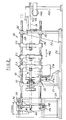
- a cut-off machine 18 embodying the present invention is adapted to receive a continuous moving length of flattened tube stock 19 from a source such as a tube mill, and to sever a plurality of individual lengths from the moving length of the tube stock as the stock moves away from the tube mill.
- Machine 18 comprises a base 20 having uprights 21, 22 (FIGS. 1B and 2) that support a plurality of tube cut-off assemblies 23.
- Assemblies 23 are mounted on a pair of vertically spaced shafts 28, 30 and are spaced from each other longitudinally of the path of tube stock 19.
- Shafts 28, 30 are slidably mounted on uprights 21, 22 by linear bearings 32, and are coupled by a vertical bar 34 and a link 40 to a crank arm 42 (FIG. 1A).
- Crank arm 42 is eccentrically connected to a gear and crank assembly 25 that is driven by an electric servo motor 24.
- shafts 28, 30 and bar 34 form a carriage assembly 41 driven by motor 24, assembly 25 and crank arm 42 to reciprocate longitudinally of the path of tube stock 19 in a direction parallel thereto.
- Rollers 36 (FIGS. 2 and 3) on opposed ends of bar 34 engage tracks 38 mounted by a support 37 on base 20 for guiding link 40 and bar 34.
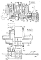
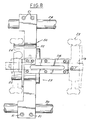
- each cut-off assembly 23 comprises a body 50 having split ends (FIGS. 4 and 7-8) clamped to shafts 28, 30 by suitable bolts 51, and a central hub portion 52 in which a hub 54 is rotatably mounted by bearings 56 (FIG. 6). Hub 54 is keyed to a drive shaft 70 so as to be rotatably driven by the drive shaft.
- a cover 55 (FIGS. 4 and 6-8) is affixed to hub 54 surrounding shaft 70 so as to form a pocket or cavity 64 surrounding a central sleeve 57 on hub 54.
- Knife assembly 58 is affixed to each hub 54 so as to rotate conjointly therewith.
- Knife assembly 58 comprises a knife blade 80 clamped by a screw 86 and a spacer 88 to one end of a knife blade support 60.
- the opposing end 62 of support 60 is enlarged, and has a central opening that encircles sleeve 57 of hub 54 within cavity 64.
- the central opening of 68 of knife holder portion 62 is enlarged radially of shaft 70 so as to accommodate limited sliding motion of holder 60 within a guide slot 66 that extends radially through hub 54.
- Knife blade 80 is fastened to the outer end of support 60. Radially outwardly of support 60, blade 80 includes a severing cavity 81 with arcuate cutting edges 84 forming a cusp or apex 82 that engages the tube stock. A slot 83 in knife blade 80 provides for lengthwise adjustment of the knife blade on the end of holder 58.
- a pair of rollers 92 (FIGS. 4-7) are mounted on a shaft 91 at the end of knife blade holder 60 on longitudinally opposed sides thereof (with respect to direction 93 of motion of stock 19).
- a severing die and cam assembly 90 is mounted on each cut-off assembly body 50 radially outwardly of hub 54 and in radial alignment with drive shaft 70.
- Each die and cam assembly 90 comprises an entrance die 102 and an exit die 104 clamped to each other by a screw 107 and a spacer 108 (FIG. 6).
- a guide opening 100 extends through the die assembly for receiving and guiding flattened tube stock.
- Entry die 102 includes an outwardly flared mouth 104 leading to its associated portion of guide 100.
- exit die 106 has an enlarged exit opening 112 communicating with its associated guide 100.
- the lower portion of each die element 102, 106 is angulated outwardly at 120 to form an entry to a blade-receiving slot between the die elements.
- a raised portion 110, 111 surrounds each guide portion 100 at the opposing faces of die elements 102, 106 to form bearing surfaces for passage of the knife blade therebetween.
- An entry guide 114 (FIGS. 7-8) is mounted on body 50 in upstream alignment with die guide opening 100, and has a slot 124 aligned with the die guide opening for receiving and guiding tube stock 19 to and through the guide opening. Each guide 114 extends upstream to a position adjacent to the upstream cutter assembly 23, as best seen in FIG. 8.
- Each die segment has a cam surface 95 in radially opposed alignment with shaft 70.
- Surface 95 has an arcuate entry portion 94 (FIG. 10), with respect to direction 97 of rotation of knife blade 80, that decreases in radius with respect to the axis of shaft 70.
- An exit surface portion 96 is complementary to surface portion 94.
- the portion 98 between surface portions 94, 96 is substantially flat and has a transverse dimension substantially equal to the transverse dimension of guide opening 100.
- the surface 95 of dies 102, 106 are aligned longitudinally of axis 70 and are at a position for opposing engagement with rollers 92.
- a servo motor 26 (FIGS. 1B-3) is mounted on upright 21 and is connected by a belt 126 and associated pulleys to a secondary shaft 122 (FIG. 3). Shaft 122 is connected in turn by a drive belt 128 and associated pulleys to drive shaft 70.
- Drive shaft 70 has opposed ends rotatably mounted on uprights 21, 22, and interconnects all of the cut-off assemblies 23 to as to drive the associated knife blades in synchronism, preferably so as to sever the tube stock at the associated cut-off assemblies substantially simultaneously.
- FIG. 13 is a functional block diagram of the machine operating mechanism and control electronics.
- Carriage-drive servo motor 24 is driven by an associate carriage controller 130 and provides a feedback signal to the carriage controller through a position encoder 132 coupled to the motor.
- blade-drive servo motor 26 is driven by an associated controller 134 and provides feedback to the controller through a position encoder 136.
- Controllers 130, 134 receive control signals from, and provide associated feedback signals to, an overall machine controller 138.
- a wheel 140 (FIGS. 1B, 2 and 13) is carried by a support 142 at a position adjacent to the path of tube stock 19 and is resiliently urged into rotating engagement with tube stock.
- Wheel 140 is coupled to an associated encoder 144 (FIGS. 1B and 13) for providing an electronic signal to machine controller 138 indicative of motion of stock 19 in direction 93 for synchronizing operation of controllers 130, 134, and of the associated motors and drive mechanisms, to longitudinal motion of tube stock 19 in the direction of its length.
- tube stock 19 is propelled in the direction 93 of its length in a continuous uninterrupted motion.
- Wheel 140 (FIGS. 2 and 13) and encoder 144 provide a corresponding control signal to machine control 138.
- tube stock 19 is propelled at substantially constant velocity, although velocity variations can be tolerated and accommodated because of wheel 140 and encoder 144 that synchronize machine operation to stock motion.
- Carriage 41 is continually reciprocated by motor 24, crank assembly 25 and crank arm 42 in the direction 146 (FIGS. 1B, 2 and 13) parallel to direction 93 of stock motion. During at least the central portion of such motion in either direction, and most importantly in the direction 93 of stock motion, the velocity of carriage motion, determined by controller 130, is equal to the velocity of stock motion.
- the knife blades 80 of the several cutter assemblies 23 are continuously driven by shaft 70 around the axis of shaft 70.
- the cutter blades intersect the path of tube stock 19 within the respective die assemblies 90, with cutting edge cusp 82 being aligned with guide 100 as shown in Fig. 4.
- rollers 92 engage entry portions 94 of cam surfaces 95. As rollers 92 traverse surfaces 94, the knife assemblies are urged radially inwardly against the associated springs 72. The rollers then engage the substantially flat portions 98 of cam surfaces 95, during traversal of which the effective knife blade radii decrease to the central position illustrated in Fig. 5, and thereafter begin increasing.
- cam surface 95 and rollers 91 on the knife assemblies is such that the knife blades traverse guides 100 with the knife cutting edges travelling in a straight line co-linear with guides 100 tangential to the axis of drive shaft 70, or chordal to the normal circular path of rotation of the knife blades, and transverse to the longitudinal dimension of the tube stock.
- the tube stock is severed by the knife blades while the knife blades travel in a straight line transverse to the stock axis, and while the knife blades are carried by the carriage longitudinally of the stock axis at the same velocity as the stock.
- the tube lengths are severed so that the tube length ends are perpendicular to the tube axis.
Landscapes
- Engineering & Computer Science (AREA)
- Mechanical Engineering (AREA)
- Shearing Machines (AREA)
- Sawing (AREA)
Claims (19)
- Maschine zum Aufnehmen eines fortlaufenden Materialstücks, wie eines Rohrmaterials (19), und Schneiden des Materials in einzelne Längen oder Stücke, umfassend:
eine Schlitteneinheit (41) mit mindestens einer Schneideanordnung (23) in Position zum Aufnehmen des fortlaufenden Materialstücks, das sich auf einer vorbestimmten Bahn in der Richtung seiner Länge bewegt,
eine Einrichtung (25) zum Hin- und Herbewegen der Schlitteneinheit längs der genannten Bahn synchron mit der Bewegung des Materialstücks,
einen an der Schlitteneinheit montierten Träger (50),
ein Schneidblatt (80) und
eine Einrichtung (60), welche das Schneidblatt am Träger für Drehung um eine Achse parallel zur genannten Bahn lagert, so daß das Schneidblatt diese Bahn schneidet bzw. kreuzt,
dadurch gekennzeichnet, daß die Vorrichtung (Maschine) ferner umfaßt:
eine Einrichtung (90, 92) zum Bewegen des Schneidblatts (80) radial einwärts von der (zur) Achse, während das Schneidblatt um diese Achse rotiert und die genannte Bahn schneidet, so daß sich das Schneidblatt, während es diese Bahn schneidet, auf einer geraden Linie quer zur genannten Bahn bewegt. - Schneidemaschine nach Anspruch 1, wobei die Radialbewegungseinrichtung eine Steuer-Kurveneinheit (90), die am Träger (50) in fester Position radial von der (zur) Achse montiert ist, und eine Kurvenfühlereinheit (92), die am Schneidblatt (80) in einer mit der Kurveneinheit in Berührung bringbaren Position gehaltert ist, aufweist.
- Schneidemaschine nach Anspruch 2, wobei die Kurveneinheit eine Formstückanordnung (die assembly) (102, 104) mit einer Führung (100) zum Aufnehmen des Materialstücks, einen quer zur Führung verlaufenden Schlitz (121) zum Aufnehmen des Schneidblatts und eine Steuerkurve mit einer der genannten Achse gegenüberstehenden Kurvenfläche (95) aufweist.
- Schneidemaschine nach Anspruch 3, wobei die Kurvenfühlereinheit ein Mittel (72), um das Schneidblatt (80) radial auswärts von der genannten Achse vorzubelasten, und ein am Schneidblatt vorgesehenes Mittel (92) aufweist, das mit der Kurvenfläche (95) in Berührung oder Anlage gelangt, wenn das Schneidblatt den Schlitz (121) durchläuft, um das Schneidblatt gegen das elastisch vorbelastende Mittel radial einwärts zu drängen.
- Schneidemaschine nach Anspruch 3 oder 4, wobei die Kurvenfläche (95) einen zwischen der genannten Bahn und der genannten Achse angeordneten flachen Flächenabschnitt aufweist.
- Schneidemaschine nach einem der Ansprüche 2 bis 5, mit einer dem Kurvenfühler (92) zugeordneten reibungsarmen Einrichtung.
- Schneidemaschine nach einem der Ansprüche 2 bis 6, wobei die Steuerkurve beabstandete Kurvenelemente (102, 106) mit miteinander fluchtenden Durchgängen (100, 104; 100, 112) für den Durchtritt des Rohrmaterials (19) umfaßt.
- Schneidemaschine nach Anspruch 7, wobei die beabstandeten Elemente axial beabstandete Kontaktelemente (110, 111) aufweisen, die mit dem Schneidblatt (80) in Berührung oder Anlage bringbar sind, wenn dieses zum Abschneiden eines Stücks des Rohrmaterials (19) bewegt wird.
- Schneidemaschine nach einem der Ansprüche 2 bis 8, wobei der Kurvenfühler beabstandete Rollen (92) am Träger (60) aufweist.
- Schneidemaschine nach einem der vorangehenden Ansprüche, wobei die Schneidblattlagereinrichtung eine Schneidblatt-Antriebswelle (70), eine für Drehung mit der Welle gekoppelte Lagernabe (54) und Mittel (62) zum Montieren des Schneidblatts an der Nabe umfaßt.
- Schneidemaschine nach einem der vorangehenden Ansprüche, wobei die Einrichtung zum Tragen oder Lagern des Schneidblatts eine rotierende Nabe (54) aufweist, das Schneidblatt (80) einen Schneidblattträger (60) mit einem in der Nabe montierten erweiterten Abschnitt (62) aufweist, die Nabe mit einer Bohrung (64) zum Aufnehmen des erweiterten Abschnitts versehen ist und die Bohrung größer ist als der erweiterte Abschnitt, so daß letzterer radial relativ zur Nabe bewegbar oder verschiebbar ist.
- Schneidemaschine nach Anspruch 11, soweit von Anspruch 4 abhängig, wobei das elastisch vorbelastende Mittel eine Feder (72) ist, die unter Druckspannung zwischen dem erweiterten Abschnitt (62) und der Nabe (54) diametral quer über die genannte Achse vom Schneidblatt (80) (aus) festgelegt ist.
- Schneidemaschine nach einem der vorangehenden Ansprüche, umfassend eine Anzahl von an der Schlitteneinheit (41) getragenen, in Längsrichtung der genannten Bahn voneinander beabstandeten Schneideanordnungen (23), wobei die Welle (70) die mehreren Schneideanordnungen miteinander verbindet und alle zugeordneten Schneidblätter antreibt.
- Schneidemaschine nach einem der vorangehenden Ansprüche, wobei die Hin- und Herbewegungseinrichtung einen ersten Elektromotor (24) umfaßt, wobei die Schneidblattlagereinrichtung einen zweiten Elektromotor (26) umfaßt und wobei die Maschine ferner eine Einrichtung (138, 140) zum Betreiben bzw. Ansteuern der ersten und zweiten Elektromotoren synchron mit der Bewegung des Materials längs der genannten Bahn aufweist.
- Schneidemaschine nach Anspruch 14, wobei die Motoransteuereinrichtung einen neben der genannten Bahn stromauf der Schneideanordnung positionierten Sensor (140) zum Erfassen der Bewegung des Materials längs der genannten Bahn und eine elektronische Steuereinheit (138) zum Betreiben bzw. Ansteuern der ersten und zweiten Motoren (24, 26) als synchrone Funktionen des Ausgangssignals vom Sensor umfaßt.
- Verfahren zum Schneiden eines fortlaufenden Rohrmaterialstücks oder -strangs (19) in einzelne Rohrmaterialstücke, umfassend die folgenden Schritte:(a) Vortreiben des Rohrmaterials mit einer kontinuierlichen, ununterbrochenen Bewegung in der Richtung seiner Länge längs einer vordefinierten Bahn,(b) ständiges Hin- und Herbewegen eines Schlittens (41) in einer Richtung parallel zu dieser Bahn synchron mit der Bewegung des Rohrmaterials längs dieser Bahn, derart, daß die Geschwindigkeit des Schlittens während eines Teils seiner Bewegung der Geschwindigkeit des Rohrmaterials in bzw. auf der genannten Bahn gleich ist, und(c) ständiges Rotierenlassen eines Schneidblatts (80) am Schlitten um eine parallel zur genannten Bahn liegende Achse und synchron mit der Bewegung des Rohrmaterials längs dieser Bahn, derart, daß das Schneidblatt während des genannten Teils eines jeden Bewegungszyklus die genannte Bahn schneidet oder kreuzt,
dadurch gekennzeichnet, daß das Verfahren die folgenden weiteren Schritte umfaßt:(d) Bewegen des Schneidblatts (80), während es die genannte Bahn schneidet, radial einwärts von der oder zur genannten Achse, so daß sich das Schneidblatt als Gesamtergebnis der Rotation und der Radialbewegung in bezug auf die genannte Achse auf einer geraden Linie quer zur genannten Bahn bewegt, während das Schneidblatt diese Bahn schneidet oder kreuzt. - Verfahren nach Anspruch 16, wobei Schritt (d) die folgenden Schritte umfaßt:(d1) Positionieren einer Rolle (92) am Schneidblatt (80),(d2) elastisches Drängen oder Vorbelasten des Schneidblatts radial auswärts von der genannten Achse und(d3) Rotierenlassen des Schneidblatts im Schritt (c), um die Rolle in Anlage gegen eine Kurvenfläche (95) neben der genannten Bahn zu bringen und damit das Schneidblatt radial einwärts zur genannten Achse hin zu drängen.
- Verfahren nach Anspruch 16 oder 17 zum Schneiden einer Anzahl von Stücken vom Streifen- bzw. Rohrmaterial, wobei Schritt (c) die Schritte eines ständigen Rotierenlassens einer Anzahl von Schneidblättern (80), derart, daß die Schneidblätter die genannte Bahn praktisch gleichzeitig schneiden oder kreuzen, umfaßt.
- Verfahren nach einem der Ansprüche 16 bis 18, umfassend die folgenden weiteren Schritte:(e) Erfassen einer Linearbewegung des Rohrmaterials (19) längs der genannten Bahn im Schritt (a) und(f) elektronisches Synchronisieren der Schritte (b) und (c) mit dieser erfaßten Linearbewegung.
Applications Claiming Priority (2)
| Application Number | Priority Date | Filing Date | Title |
|---|---|---|---|
| US07/462,049 US5063801A (en) | 1989-01-23 | 1990-01-08 | Cut-off machine and method for tubing |
| US462049 | 1990-01-08 |
Publications (3)
| Publication Number | Publication Date |
|---|---|
| EP0440327A2 EP0440327A2 (de) | 1991-08-07 |
| EP0440327A3 EP0440327A3 (en) | 1991-12-27 |
| EP0440327B1 true EP0440327B1 (de) | 1994-07-27 |
Family
ID=23834995
Family Applications (1)
| Application Number | Title | Priority Date | Filing Date |
|---|---|---|---|
| EP91300019A Expired - Lifetime EP0440327B1 (de) | 1990-01-08 | 1991-01-02 | Verfahren und Vorrichtung zum Schneiden von Rohren |
Country Status (5)
| Country | Link |
|---|---|
| US (1) | US5063801A (de) |
| EP (1) | EP0440327B1 (de) |
| JP (1) | JPH04275820A (de) |
| CA (1) | CA2033466A1 (de) |
| DE (1) | DE69103033T2 (de) |
Families Citing this family (14)
| Publication number | Priority date | Publication date | Assignee | Title |
|---|---|---|---|---|
| US5243889A (en) * | 1991-04-09 | 1993-09-14 | Wallis Bernard J | Tube cut off machine |
| US5301584A (en) * | 1993-03-15 | 1994-04-12 | Touchstone, Inc. | Zero clearance high speed welded seam tube cut-off die |
| JP2737609B2 (ja) * | 1993-08-03 | 1998-04-08 | 株式会社デンソー | 切断機 |
| US5777879A (en) * | 1995-09-05 | 1998-07-07 | Minnesota Mining And Manufacturing Company | Process-to-mark control system |
| EP0932469B1 (de) * | 1996-09-23 | 2002-10-30 | Ahti Niemelä | Sägemaschine |
| US5967010A (en) * | 1998-04-10 | 1999-10-19 | Cambridge Industries, Inc. | Cutting apparatus and cutting process for hollow plastic molded articles |
| AU2341900A (en) | 1998-09-03 | 2000-04-10 | Lockheed Martin Corporation | Automated fuel tank assembly system and method |
| DE102005062860A1 (de) * | 2005-12-29 | 2007-07-12 | Robert Bosch Gmbh | Verfahren und Vorrichtung zum Herstellen gebogener Federelemente |
| JP4880356B2 (ja) * | 2006-05-17 | 2012-02-22 | モリマシナリー株式会社 | 熱交換器用チューブの製造ラインに用いる切断装置 |
| DE102007007061A1 (de) * | 2007-02-08 | 2008-08-14 | Schumag Ag | Trenneinrichtung für im Wesentlichen lineare Werkstücke und Verfahren zum Trennen von im Wesentlichen linearen Werkstücken |
| DE102014117618B3 (de) | 2014-12-01 | 2016-03-31 | Rattunde & Co Gmbh | Senkrechte Sägenut |
| CN108746824A (zh) * | 2018-08-16 | 2018-11-06 | 大连立达工业设备有限公司 | 在线连续切割薄壁铝管切断机 |
| CN108927567B (zh) * | 2018-08-20 | 2024-06-25 | 镇江裕太防爆电加热器有限公司 | 一种用于三角形镁管烧结设备的切断结构 |
| CN119658756B (zh) * | 2023-09-20 | 2026-01-16 | 南通年盛机械配件有限公司 | 一种核电管道金属保温层切割装置 |
Family Cites Families (10)
| Publication number | Priority date | Publication date | Assignee | Title |
|---|---|---|---|---|
| US2416652A (en) * | 1941-02-05 | 1947-02-25 | Bethlebem Steel Company | Automatic cutting apparatus |
| US2575417A (en) * | 1947-01-24 | 1951-11-20 | Joseph Shapiro | Straw cutting mechanism for straw manufacturing machines |
| US3082655A (en) * | 1956-06-05 | 1963-03-26 | Voigt Alfred | Wire straightening and cut-off machines |
| US3254549A (en) * | 1960-09-21 | 1966-06-07 | Ronai Ernest Winston | Tube cutting means for tube winding machines |
| DE6801078U (de) * | 1968-10-04 | 1969-02-27 | Conduco Ag | Vorrichtung zur herstellung von schlauch- oder rohrstuecken aus einem warmplastischen kunststoff |
| DE3231825C1 (de) * | 1982-08-24 | 1984-01-26 | Justus Technik GmbH Industrie-Anlagen, 2000 Hamburg | Vorrichtung zum Zerschneiden von strang- oder stabfoermigem Gut |
| US4462290A (en) * | 1982-10-27 | 1984-07-31 | Wallis Bernard J | Tube cut-off machine |
| EP0195677A3 (de) * | 1985-03-01 | 1989-08-02 | Hokkai Can Co., Ltd. | Vorrichtung zum Schneiden von langen Produkten |
| US4643063A (en) * | 1985-08-01 | 1987-02-17 | Mckenica Inc. | Tube cutoff machine |
| US4919025A (en) * | 1988-10-24 | 1990-04-24 | General Motors Corporation | Method and apparatus for processing continuously manufactured tubing |
-
1990
- 1990-01-08 US US07/462,049 patent/US5063801A/en not_active Expired - Lifetime
- 1990-12-28 JP JP2418078A patent/JPH04275820A/ja not_active Withdrawn
- 1990-12-31 CA CA002033466A patent/CA2033466A1/en not_active Abandoned
-
1991
- 1991-01-02 DE DE69103033T patent/DE69103033T2/de not_active Expired - Fee Related
- 1991-01-02 EP EP91300019A patent/EP0440327B1/de not_active Expired - Lifetime
Also Published As
| Publication number | Publication date |
|---|---|
| JPH04275820A (ja) | 1992-10-01 |
| US5063801A (en) | 1991-11-12 |
| DE69103033T2 (de) | 1994-12-08 |
| EP0440327A3 (en) | 1991-12-27 |
| CA2033466A1 (en) | 1991-07-09 |
| EP0440327A2 (de) | 1991-08-07 |
| DE69103033D1 (de) | 1994-09-01 |
Similar Documents
| Publication | Publication Date | Title |
|---|---|---|
| EP0440327B1 (de) | Verfahren und Vorrichtung zum Schneiden von Rohren | |
| EP0507750B1 (de) | Maschine zum Schneiden von Materialbahnrollen | |
| US4922775A (en) | Device for cutting contoured labels | |
| US5243889A (en) | Tube cut off machine | |
| US4956987A (en) | Rotary cutter for cutting a continuous corrugated strip | |
| US5454286A (en) | Cutter for cutting a continuous corrugated strip | |
| KR20010095070A (ko) | 절단선의 2 에지를 연결하는 닉을 파단하기 위한 장치 | |
| US4919025A (en) | Method and apparatus for processing continuously manufactured tubing | |
| US4939967A (en) | Cut-off machine | |
| US4462290A (en) | Tube cut-off machine | |
| CN107344292B (zh) | 一种铜管包装用铜扣加工设备及铜扣加工方法 | |
| EP1034861A2 (de) | Maschine zum Schneiden und Formen von Draht | |
| US2768692A (en) | Cut-off mechanism | |
| MY141482A (en) | Rotary apparatus and method | |
| US3901114A (en) | Saw assembly | |
| EP2090535B1 (de) | Vorrichtung zum Querschneiden von Bahnmaterialen | |
| US3808861A (en) | Apparatus for continuously forming a tube and continually cutting the tube into substantially uniform lengths | |
| EP4065322B1 (de) | System zur positionierung eines werkzeugs auf einer welle und eine bahnschneidevorrichtung, die dieses system zur positionierung eines werkzeugs auf einer welle umfasst | |
| CN213381709U (zh) | 烘培纸平切机 | |
| EP0066744B1 (de) | Vorrichtung zum Zuführen einer Kunststoffolienbahn für eine Trennpresse | |
| JPH11151611A (ja) | コルゲートフィンの切断装置 | |
| JPH0478407B2 (de) | ||
| JP2869626B2 (ja) | 直線切断機及び走間切断方法 | |
| US3487738A (en) | Apparatus for cutting a continuously moving strip of material | |
| CN113414444B (zh) | 一种钢带裁剪装置及方法 |
Legal Events
| Date | Code | Title | Description |
|---|---|---|---|
| PUAI | Public reference made under article 153(3) epc to a published international application that has entered the european phase |
Free format text: ORIGINAL CODE: 0009012 |
|
| AK | Designated contracting states |
Kind code of ref document: A2 Designated state(s): DE FR GB IT |
|
| PUAL | Search report despatched |
Free format text: ORIGINAL CODE: 0009013 |
|
| AK | Designated contracting states |
Kind code of ref document: A3 Designated state(s): DE FR GB IT |
|
| 17P | Request for examination filed |
Effective date: 19920611 |
|
| 17Q | First examination report despatched |
Effective date: 19930427 |
|
| GRAA | (expected) grant |
Free format text: ORIGINAL CODE: 0009210 |
|
| AK | Designated contracting states |
Kind code of ref document: B1 Designated state(s): DE FR GB IT |
|
| ITF | It: translation for a ep patent filed | ||
| REF | Corresponds to: |
Ref document number: 69103033 Country of ref document: DE Date of ref document: 19940901 |
|
| ET | Fr: translation filed | ||
| PG25 | Lapsed in a contracting state [announced via postgrant information from national office to epo] |
Ref country code: GB Effective date: 19950102 |
|
| PLBE | No opposition filed within time limit |
Free format text: ORIGINAL CODE: 0009261 |
|
| STAA | Information on the status of an ep patent application or granted ep patent |
Free format text: STATUS: NO OPPOSITION FILED WITHIN TIME LIMIT |
|
| 26N | No opposition filed | ||
| GBPC | Gb: european patent ceased through non-payment of renewal fee |
Effective date: 19950102 |
|
| PG25 | Lapsed in a contracting state [announced via postgrant information from national office to epo] |
Ref country code: FR Effective date: 19950929 |
|
| PG25 | Lapsed in a contracting state [announced via postgrant information from national office to epo] |
Ref country code: DE Effective date: 19951003 |
|
| REG | Reference to a national code |
Ref country code: FR Ref legal event code: ST |
|
| PG25 | Lapsed in a contracting state [announced via postgrant information from national office to epo] |
Ref country code: IT Free format text: LAPSE BECAUSE OF NON-PAYMENT OF DUE FEES;WARNING: LAPSES OF ITALIAN PATENTS WITH EFFECTIVE DATE BEFORE 2007 MAY HAVE OCCURRED AT ANY TIME BEFORE 2007. THE CORRECT EFFECTIVE DATE MAY BE DIFFERENT FROM THE ONE RECORDED. Effective date: 20050102 |