EP0440330B1 - Connecteur - Google Patents
Connecteur Download PDFInfo
- Publication number
- EP0440330B1 EP0440330B1 EP91300069A EP91300069A EP0440330B1 EP 0440330 B1 EP0440330 B1 EP 0440330B1 EP 91300069 A EP91300069 A EP 91300069A EP 91300069 A EP91300069 A EP 91300069A EP 0440330 B1 EP0440330 B1 EP 0440330B1
- Authority
- EP
- European Patent Office
- Prior art keywords
- detecting
- electricity conducting
- locking
- connector
- elastic beam
- Prior art date
- Legal status (The legal status is an assumption and is not a legal conclusion. Google has not performed a legal analysis and makes no representation as to the accuracy of the status listed.)
- Expired - Lifetime
Links
- 230000005611 electricity Effects 0.000 claims description 62
- 230000004308 accommodation Effects 0.000 description 3
- 239000002184 metal Substances 0.000 description 3
- 230000004888 barrier function Effects 0.000 description 2
- 238000003780 insertion Methods 0.000 description 2
- 230000037431 insertion Effects 0.000 description 2
- 238000001514 detection method Methods 0.000 description 1
- 230000006866 deterioration Effects 0.000 description 1
- 230000001627 detrimental effect Effects 0.000 description 1
- 238000006073 displacement reaction Methods 0.000 description 1
- 230000000694 effects Effects 0.000 description 1
- 230000007257 malfunction Effects 0.000 description 1
- 239000000758 substrate Substances 0.000 description 1
Images




Classifications
-
- H—ELECTRICITY
- H01—ELECTRIC ELEMENTS
- H01R—ELECTRICALLY-CONDUCTIVE CONNECTIONS; STRUCTURAL ASSOCIATIONS OF A PLURALITY OF MUTUALLY-INSULATED ELECTRICAL CONNECTING ELEMENTS; COUPLING DEVICES; CURRENT COLLECTORS
- H01R13/00—Details of coupling devices of the kinds covered by groups H01R12/70 or H01R24/00 - H01R33/00
- H01R13/64—Means for preventing incorrect coupling
- H01R13/641—Means for preventing incorrect coupling by indicating incorrect coupling; by indicating correct or full engagement
-
- H—ELECTRICITY
- H01—ELECTRIC ELEMENTS
- H01R—ELECTRICALLY-CONDUCTIVE CONNECTIONS; STRUCTURAL ASSOCIATIONS OF A PLURALITY OF MUTUALLY-INSULATED ELECTRICAL CONNECTING ELEMENTS; COUPLING DEVICES; CURRENT COLLECTORS
- H01R13/00—Details of coupling devices of the kinds covered by groups H01R12/70 or H01R24/00 - H01R33/00
- H01R13/62—Means for facilitating engagement or disengagement of coupling parts or for holding them in engagement
- H01R13/629—Additional means for facilitating engagement or disengagement of coupling parts, e.g. aligning or guiding means, levers, gas pressure electrical locking indicators, manufacturing tolerances
-
- H—ELECTRICITY
- H01—ELECTRIC ELEMENTS
- H01R—ELECTRICALLY-CONDUCTIVE CONNECTIONS; STRUCTURAL ASSOCIATIONS OF A PLURALITY OF MUTUALLY-INSULATED ELECTRICAL CONNECTING ELEMENTS; COUPLING DEVICES; CURRENT COLLECTORS
- H01R13/00—Details of coupling devices of the kinds covered by groups H01R12/70 or H01R24/00 - H01R33/00
- H01R13/66—Structural association with built-in electrical component
- H01R13/70—Structural association with built-in electrical component with built-in switch
- H01R13/701—Structural association with built-in electrical component with built-in switch the switch being actuated by an accessory, e.g. cover, locking member
-
- H—ELECTRICITY
- H01—ELECTRIC ELEMENTS
- H01R—ELECTRICALLY-CONDUCTIVE CONNECTIONS; STRUCTURAL ASSOCIATIONS OF A PLURALITY OF MUTUALLY-INSULATED ELECTRICAL CONNECTING ELEMENTS; COUPLING DEVICES; CURRENT COLLECTORS
- H01R13/00—Details of coupling devices of the kinds covered by groups H01R12/70 or H01R24/00 - H01R33/00
- H01R13/66—Structural association with built-in electrical component
- H01R13/70—Structural association with built-in electrical component with built-in switch
- H01R13/703—Structural association with built-in electrical component with built-in switch operated by engagement or disengagement of coupling parts, e.g. dual-continuity coupling part
Definitions
- the present invention relates to a connector according to the preamble of Claim 1.
- a fitted-posture locking mechanism is provided on a pair of female and male connector housings that are fitted together for connection for locking the two connector housings properly fitted together in such a proper fitted posture.
- two connector housings are brought into use while they are in a semi-fitted state in which the connector housings are not fully fitted together or in a state in which a locking operation is not being properly performed, thereby causing electrical failures while in use.
- This is due to the facts that a certain magnitude of insertion force is required to fit the connector housings together and that the locking mechanism is subject to deformation and/or breakage.
- the official gazette of Japanese Utility Model Laid-Open No. 16080/1989 discloses a connector provided with an electrical detecting mechanism for detecting the above-mentioned semi-fitted state or state in which a locking operation is not being properly performed in a simple fashion.
- a "metal contact plate extending from a substrate in a cantilever-like fashion and having bifurcated contact portions at a free end thereof" is provided on one of connector housings, and one of the contact portions at the free end is press held by the leading end of a lock arm of the other connector housing that is properly fitted in the one of connector housings onto a detecting electricity conducting terminal provided therebelow, while the other contact portion at the free end is always kept in contact with another detecting electricity conducting terminal, thereby making it possible to detect a proper operation of the lock arm through the relative electricity conduction between these two electricity conducting terminals.
- EP-A-0 300 767 discloses a connector having a fitted posture locking mechanism comprising a lock arm provided on one of connector housings and a locking portion provided on the other connector housing so as to be brought into engagement with said lock arm, in which a fittingly locked state detecting mechanism comprises: a detecting electricity conducting body having a pressure sensing switch element portion and a pair of electricity conducting plates extending rearwardly such that said pressure sensing switch element portion is arranged so as to face the underside of said lock arm in a fitted posture; a pair of detecting terminals connected to electrically conducting cords; and an operating portion provided on said lock arm, whereby said pressure sensing switch element portion is pressed down by said operating portion when said operating portion is put in a proper fittingly locked state, thereby making it possible to establish a relative electrical communication between said electricity conducting cords via said detecting terminals.
- the locking portion is provided on a locking elastic beam of the other connector housing, and the detecting terminals have biasing spring contact portions intended not only to be brought into elastic contact with said pair of electricity conducting plates but also to lift up said locking elastic beam and mounted between said locking elastic beam and a side wall of a connector housing main body of said other connector housing.
- the pressure sensing switch element acting as a section where a detection takes place has extremely good durability and the quality enabling the continuity of a precise switching operation.
- the position of the detecting terminals that are provided downstream of the pressure sensing switch element to relay and transfer the switching operation of the same switching element is not subject to external influences such as external pressing. Due to this, a stable transfer operation can be attained. Therefore, an electric signal indicating a fittingly locked state sent from the lock arm is extremely accurately transferred to the electricity conducting cords, and this serves to highly improved and stabilize the accuracy with which whether or not the connector housings are in a proper fittingly locked state is detected. Moreover, this also serves to enable the detecting performance of the detecting terminals to continue with good durability.
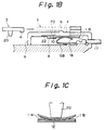
- a connector with a fitted-posture locking mechanism in a connector with a fitted-posture locking mechanism, the front half portion of a female connector housing 1 accommodating therein female terminals (not shown) and a male connector housing 2 accommodating therein male terminals (not shown) are fitted together for connection, and this time a locking projection 4 formed on the leading end of a lock arm 3 provided front-ward of the male connector housing 2 is brought into engagement with locking portions 5 provided on a locking elastic arm 6 bridged longitudinal of the female connector housing 1 at an intermediate position along the length thereof in such a manner as to project therefrom so that the female and male connector housings are locked in a proper fitted posture.
- An electricity conducting body receiving portion 8 formed as an integral part of the locking elastic beam 6 is provided on the female connector housing in a gap provided between the locking elastic beam 6 and the top side of a connector housing main body 7.
- a detecting electricity conducting body 9 having a pressure sensing switch element 10 at a front end thereof is mounted on the electricity conducting body 8 from the rear thereof.
- a pair of electricity conducting terminals 16A, 16B to which electricity cords 17 are connected, respectively, are inserted beneath the rear half portion of the detecting electricity conducting body 9 and secured in place therein such that the contact portions 18 of the respective electricity conducting terminals 16A, 16B are brought into contact with a pair of electricity conducting plates 11A, 11B for electricity conduction.
- a projecting operating portion 20 is provided on the lock arm 3 of the male connector housing 2 at an intermediate position along the length thereof in such a manner as to project downwardly therefrom.
- the operating portion 20 enters an insertion gap 19 formed at an intermediate position along the width of the locking elastic bridge 6 on the associated connector housing, and presses down the pressure sensing switch element portion 10 of the detecting electricity conducting body 9 to switch on the same, whereby the electricity conducting plates 11A, 11B are electrically conducted to each other.
- This establishes an electrical communication between the electricity conducting terminals 16A, 16B that are in electrical contact with the electricity conducting plates 11A, 11B, thereby making it possible to detect that the female and male connector housings 1, 2 are in a proper fittingly locked state.
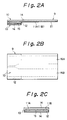
- the detecting electricity conducting body 9 has the pressure sensing switch element portion 10 comprising a known pressure sensing switch element structure constituted by a combination of the pair of electricity conducting plates 11A, 11B arranged in parallel and a single communicating plate 12 arranged so as to face the electricity conducting plates 11A, 11B via a clearance 15 in a transverse direction.
- the pressure sensing switch element portion 10 when the pressure sensing switch element portion 10 is forcibly pressed down by the operating portion 20, the electricity conducting plates 11A, 11B are brought into contact with the communicating plate 12 so as to generate an electricity conduction therebetween, while the electricity conducting plates 11A, 11B and the communicating plate 12 separate from each other when the operating portion 20 is not pressed down, remaining in a free state.
- These electricity conducting plates 11A, 11B extend rearwardly from the pressure sensing switch element portion 10 so as to be formed into the plate-like detecting electricity conducting body 9 that forms an associated contact portion 21 to which the detecting terminals 16A, 16B are brought into contact.
- reference numeral 13 denotes a liner for the clearance 15, reference numeral 14 a protection film for the electricity conducting plates 11A, 11B and the communicating plate 12.
- the connector according to the embodiment shown in Figs. 1 and 2 functions as follows.
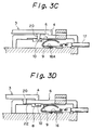
- FIG. 3 showing a state in which the connector in operation, when the female and male connector housings 1, 2 start to be fitted together, as shown in Figs. 3(A), (B), the locking projection 4 of the lock arm 3 comes into a physical collision with the locking portion 5 of the locking elastic beam 6 so as to elastically flex the locking elastic beam 6, and this allows the locking projection 4 to pass over the locking portion 5.
- the operating portion 20 does not come into a physical collision with the pressure sensing switch element portion 10 being lowered together with the locking elastic beam 6.
- the locking elastic beam 6 is not at all displaced downwardly or is displaced insufficiently, and the lower most end of the operating portion 20 comes into a physical collision with the barrier portion 22 to thereby check the advance of the lock arm 3, thereby making it possible to accurately detect the failure of the locking elastic beam 6.
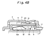
- the detecting electricity conducting body 9 having the pressure sensing switch element portion 10 and the detecting terminals 16A, 16B in tended to be brought into contact with the pair of electricity conducting plates 11A, 11B of the detecting electricity conducting body 9 for electricity conduction are provided on one of connector housings, but the detecting electricity conducting body 9 is folded into a U shape at an intermediate position along the length thereof and is inserted from the rear of a locking elastic beam 6 so as to be secured in place such that a contact portion 18 of the electricity conducting terminals 16A, 16B is brought into press contact with the electricity conducting plates 11A, 11B exposed on the lower outside of the detecting electricity conducting body 9.
- This contact portion 18 is formed into a spring contact portion 18′ having a biasing force for upwardly biasing the locking elastic beam 6 from below as well as a elastically pressing force required to press contact the contact portion 18 against the electricity conducting plates 11A, 11B.
- the lock arm 3 of this second embodiment has a configuration defined by a locking projection 4 provided at the leading end thereof and an operating portion 20 provided at the center of the locking projection 4 in such a manner as to project therefrom, and this operating portion 20 is constructed so as to press down the pressure sensing switch element portion 10 when the locking projection 4 is properly locked.
- Fig. 5 shows a third embodiment of the present invention, in which the biasing means for lifting up the locking elastic beam 6 of the second embodiment is formed as an independent member with a view to further improving the function thereof.
- a detecting terminal accommodation chamber 23 is provided on the locking elastic beam 6, and the detecting terminals 16A, 16B are mounted therein such that the contact portion 18 faces downwardly.
- the detecting electricity conducting body 9 is laid out in the detecting terminal accommodation chamber 23 with the rear half of the electricity conducting plates 11A, 11B being exposed upwardly, and the pressure sensing switch element portion 10 is laid out between the locking portion 5 of the locking elastic beam 6 and the front edge of the detecting terminal accommodation chamber 23 so as to be pressed down by the operating portion 20 of the lock arm 3 of the associated connector housing.
- a biasing spring body 25 having a biasing force for lifting up the locking elastic beam 6 from below is mounted in a gap 24 formed beneath the locking elastic beam 6.
- this biasing spring body 25 functions exclusively to prevent the plastic deformation of the locking elastic beam 6, the function and effectiveness of preventing such deformation can be further improved.
- the connector according to the present invention has superior detecting accuracy with which whether connector housings are in a proper fittingly locked state or in a semi-fitted state in which the connector housings fail to be properly fitted together is detected in a precise manner, as well as the detecting performance enabling such detecting accuracy to continue with good durability, whereby the reliability in detecting a fittingly locked state of a connector is improved, while the structure of the fitted-posture locking mechanism is stabilized.
Landscapes
- Details Of Connecting Devices For Male And Female Coupling (AREA)
Claims (4)
- Un connecteur ayant un dispositif de verrouillage en position assemblée ou ajustée, comprenant un bras verrouilleur (3) prévu sur l'un des boîtiers de connecteur (2) et une portion de verrouillage (5) prévue sur l'autre boîtier de connecteur (1) de façon à être mise en engagement avec ledit bras verrouilleur, dans lequel un dispositif de détection de l'état verrouillé de l'assemblage ou d'ajustage comprend :
un corps détecteur et électriquement conducteur (9) comprenant une portion d'élément commutateur de détection de pression (10) et une paire de plaques électriquement conductrices (11A, 11B) s'étendant vers l'arrière de façon que la portion d'élément commutateur de détection de pression soient disposés de façon à être en regard de la face inférieure dudit bras verrouilleur dans une position assemblée;
une paire de bornes détectrice (16A, 16B) reliées à des câbles électriquement conducteurs (17); et
une portion de manoeuvre (20) prévue sur le bras verrouilleur, de façon que la portion d'élément commutateur de détection de pression soit pressée vers le bas par ladite portion de manoeuvre lorsque ladite portion de manoeuvre est mise dans un état verrouillée de l'assemblage approprié, en rendant ainsi possible d'établir une communication électrique relative entre lesdits câbles électriquement conducteurs par l'intermédiaire desdites bornes de détection,
caractérisé en ce que la portion de verrouillage (5) est prévue sur une poutre élastique de verrouillage (6) de l'autre boîtier de connecteur (1), et les bornes détectrices (16A, 16B) comportent des portions de contact élastique de polarisation ou de précontrainte 18′ destinées non seulement à être mises en contact élastique avec ladite paire de plaques électriquement conductrices mais également à soulever ladite poutre élastique de verrouillage et être montée entre ladite poutre élastique de verrouillage et une paroi latérale d'un corps principal de boîtier de connecteur dudit autre boîtier de connecteur. - Un connecteur selon la revendication 1, dans lequel la paire précitée de bornes détectrices (16A, 16B) comprend des câbles électriquement conducteurs et des portions de contact mises en contact avec les plaques électriquement conductrices précitées du corps électriquement conducteur de détection et sont logés dans une chambre de logement de bornes de détection (23) recouvrant la portion de la moitié arrière dudit corps électriquement conducteur et de détection; et dans lequel
le dispositif précité comprend en outre un corps élastique ou à ressort de précontrainte ou de polarisation (25) prévu dans un espace en dessous de ladite poutre élastique de verrouillage pour soulever ladite poutre élastique de verrouillage. - Connecteur selon l'une des revendications 1 ou 2, dans lequel le corps électriquement conducteur et détecteur (9) est réalisé de façon à avoir la forme d'un U.
- Un connecteur selon la revendication 1 ou 2, dans lequel le corps détecteur électriquement conducteur (9) est réalisé sous forme d'une plaque.
Applications Claiming Priority (2)
| Application Number | Priority Date | Filing Date | Title |
|---|---|---|---|
| JP2002140A JPH03208275A (ja) | 1990-01-08 | 1990-01-08 | コネクタの嵌合ロックの検知方法と、それを用いたコネクタ |
| JP2140/90 | 1990-01-08 |
Publications (2)
| Publication Number | Publication Date |
|---|---|
| EP0440330A1 EP0440330A1 (fr) | 1991-08-07 |
| EP0440330B1 true EP0440330B1 (fr) | 1995-12-13 |
Family
ID=11521036
Family Applications (1)
| Application Number | Title | Priority Date | Filing Date |
|---|---|---|---|
| EP91300069A Expired - Lifetime EP0440330B1 (fr) | 1990-01-08 | 1991-01-04 | Connecteur |
Country Status (4)
| Country | Link |
|---|---|
| US (1) | US5112246A (fr) |
| EP (1) | EP0440330B1 (fr) |
| JP (1) | JPH03208275A (fr) |
| DE (1) | DE69115301T2 (fr) |
Families Citing this family (26)
| Publication number | Priority date | Publication date | Assignee | Title |
|---|---|---|---|---|
| JP3196968B2 (ja) * | 1992-04-16 | 2001-08-06 | タイコエレクトロニクスアンプ株式会社 | 電気コネクタ |
| US5417586A (en) * | 1993-04-14 | 1995-05-23 | Yazaki Corporation | Fitting detection connector |
| US5464353A (en) * | 1993-04-21 | 1995-11-07 | Sumitomo Wiring Systems, Ltd. | Lock connector |
| US5562486A (en) * | 1993-04-21 | 1996-10-08 | Sumitomo Wiring Systems, Ltd. | Lock detection connector |
| JP2939851B2 (ja) * | 1993-09-24 | 1999-08-25 | モレックス インコーポレーテッド | 嵌合接続検知機能を有する電気コネクタ |
| JP3264297B2 (ja) * | 1993-09-30 | 2002-03-11 | 矢崎総業株式会社 | コネクタの結合検知装置 |
| JPH07272794A (ja) * | 1994-03-31 | 1995-10-20 | Mitsubishi Electric Corp | コネクタ装置 |
| US5616039A (en) * | 1995-01-23 | 1997-04-01 | Paragon Electric Company, Inc. | System for selectively effecting electrical connection among a plurality of loci in a housing |
| US5984705A (en) * | 1996-12-02 | 1999-11-16 | Sumitomo Wiring Systems, Ltd. | Connector |
| JP3405954B2 (ja) * | 2000-03-13 | 2003-05-12 | 日本圧着端子製造株式会社 | コネクタのロック構造 |
| DE10261016A1 (de) * | 2002-12-24 | 2004-07-08 | Robert Bosch Gmbh | Steckkontrolle zur Detektion einer korrekt ausgeführten elektrischen Steckverbindung |
| JP4508888B2 (ja) * | 2005-01-21 | 2010-07-21 | 国産電機株式会社 | エンジン駆動電源装置 |
| WO2008142490A1 (fr) * | 2007-05-24 | 2008-11-27 | Fci | Dispositif de détection d'accouplement, connecteur et ensemble connecteur associés |
| DE102008035193A1 (de) * | 2008-07-28 | 2010-02-11 | Tyco Electronics Amp Gmbh | Kontrollierbare Steckverbindung und Verfahren zur Kontrolle des Steckzustandes einer Steckverbindung |
| US9007206B2 (en) * | 2010-01-29 | 2015-04-14 | Surtec Industries, Inc. | Patch panel and intelligent structured cabling system |
| DE102011017324A1 (de) * | 2011-04-16 | 2012-10-18 | Daimler Ag | On-Board-Diagnoseeinheit für ein Kraftfahrzeug |
| CN103513144B (zh) * | 2012-06-29 | 2016-12-21 | 联想企业解决方案(新加坡)有限公司 | 电子系统、连接故障报告系统及相关方法 |
| JP5889432B2 (ja) * | 2012-10-22 | 2016-03-22 | 古河電気工業株式会社 | 給電コネクタ |
| US9703741B2 (en) | 2013-10-31 | 2017-07-11 | Commscope Technologies Llc | Connector with a termination module |
| US10103488B2 (en) | 2016-12-20 | 2018-10-16 | Ford Global Technologies, Llc | Vehicle connectors for monitoring connection with trailer connectors |
| JP6799518B2 (ja) * | 2017-10-12 | 2020-12-16 | 株式会社オートネットワーク技術研究所 | センサユニット |
| DE102018215574A1 (de) | 2018-09-13 | 2020-03-19 | Bayerische Motoren Werke Aktiengesellschaft | Stecker-Steckeraufnahme-Vorrichtung |
| CN110118524B (zh) * | 2019-05-15 | 2022-02-25 | 胡天旭 | 一种附着式电阻应变传感器总成及其安装工艺 |
| CN110466354B (zh) * | 2019-08-29 | 2024-11-22 | 珠海广通汽车有限公司 | 连接器状态确定方法及相关装置 |
| KR102843254B1 (ko) * | 2020-05-04 | 2025-08-05 | 주식회사 엘지에너지솔루션 | 커넥터 모듈 |
| US12413026B2 (en) * | 2022-12-19 | 2025-09-09 | GM Global Technology Operations LLC | Monitoring the position of an electrical connector |
Family Cites Families (11)
| Publication number | Priority date | Publication date | Assignee | Title |
|---|---|---|---|---|
| US2824183A (en) * | 1955-10-31 | 1958-02-18 | Nottingham & Co Inc J B | Cable connectors or couplers embodying novel circuit making and breaking devices |
| US3851946A (en) * | 1971-11-05 | 1974-12-03 | R Piaget | Cable connecting assembly |
| DE2843247A1 (de) * | 1978-10-04 | 1980-04-17 | Dornier Gmbh | Elektrische steckvorrichtung |
| US4386818A (en) * | 1981-04-27 | 1983-06-07 | Amp Incorporated | Polarity indicating connector for battery jumper cables |
| US4602135A (en) * | 1985-05-30 | 1986-07-22 | Phalen Robert F | Membrane switch |
| DE8700010U1 (de) * | 1986-03-08 | 1987-03-05 | Manfred Fladung GmbH, 8752 Mömbris | Steckvorrichtung |
| JPH0636384B2 (ja) * | 1987-04-02 | 1994-05-11 | アンプ インコーポレーテッド | 電気コネクタ組立体 |
| US4786258A (en) * | 1987-05-13 | 1988-11-22 | Amp Incorporated | Electrical connector with shunt |
| JPH043419Y2 (fr) * | 1987-07-21 | 1992-02-03 | ||
| JPH01137572A (ja) * | 1987-11-25 | 1989-05-30 | Yazaki Corp | コネクタのロック機構 |
| JPH01132076U (fr) * | 1988-03-04 | 1989-09-07 |
-
1990
- 1990-01-08 JP JP2002140A patent/JPH03208275A/ja active Pending
-
1991
- 1991-01-04 EP EP91300069A patent/EP0440330B1/fr not_active Expired - Lifetime
- 1991-01-04 DE DE69115301T patent/DE69115301T2/de not_active Expired - Fee Related
- 1991-01-08 US US07/638,532 patent/US5112246A/en not_active Expired - Fee Related
Also Published As
| Publication number | Publication date |
|---|---|
| JPH03208275A (ja) | 1991-09-11 |
| EP0440330A1 (fr) | 1991-08-07 |
| DE69115301T2 (de) | 1996-05-09 |
| DE69115301D1 (de) | 1996-01-25 |
| US5112246A (en) | 1992-05-12 |
Similar Documents
| Publication | Publication Date | Title |
|---|---|---|
| EP0440330B1 (fr) | Connecteur | |
| US5131865A (en) | Connector apparatus with coupling detecting function | |
| EP0645848B1 (fr) | Système de détection pour un connecteur enfichable | |
| EP0448084B1 (fr) | Appareil de détection d'engagement d'un connecteur | |
| US5651693A (en) | Connection sensor and short-circuiting contact for connector | |
| US6371796B2 (en) | Waterproof half-fitting detection connector with waterproof cap | |
| JP2874151B2 (ja) | コネクタの結合検知装置 | |
| JP2907373B2 (ja) | コネクタのロック結合検知構造 | |
| JPH088542Y2 (ja) | 完全嵌合検出機構付コネクタ | |
| JP3264305B2 (ja) | 結合検知装置を備えたコネクタ | |
| EP0448083B1 (fr) | Dispositif détectant l'engagement d'un connecteur | |
| JP3552192B2 (ja) | コネクタロック構造 | |
| US5509817A (en) | Connector having short circuit terminal | |
| EP0657968B1 (fr) | Connecteur à détection de verrouillage | |
| KR20040034532A (ko) | 전기 커넥터 | |
| EP0471994B1 (fr) | Connecteur électrique avec sécurité contre défaillances | |
| EP1065757B1 (fr) | Connecteur ayant des moyens de détection d'engagement | |
| JP3596702B2 (ja) | コネクタ嵌合検知構造 | |
| JP3264297B2 (ja) | コネクタの結合検知装置 | |
| JP2727367B2 (ja) | コネクタ | |
| JP3613374B2 (ja) | コネクタ | |
| JP3189202B2 (ja) | コネクタの結合検知装置 | |
| JP3619300B2 (ja) | コネクタの結合検知装置 | |
| JPH0770339B2 (ja) | コネクタの結合検知装置 | |
| JP3296961B2 (ja) | 半嵌合検知コネクタ |
Legal Events
| Date | Code | Title | Description |
|---|---|---|---|
| PUAI | Public reference made under article 153(3) epc to a published international application that has entered the european phase |
Free format text: ORIGINAL CODE: 0009012 |
|
| 17P | Request for examination filed |
Effective date: 19910125 |
|
| AK | Designated contracting states |
Kind code of ref document: A1 Designated state(s): DE FR GB |
|
| RAP1 | Party data changed (applicant data changed or rights of an application transferred) |
Owner name: SUMITOMO WIRING SYSTEMS, LTD. |
|
| 17Q | First examination report despatched |
Effective date: 19940623 |
|
| GRAA | (expected) grant |
Free format text: ORIGINAL CODE: 0009210 |
|
| AK | Designated contracting states |
Kind code of ref document: B1 Designated state(s): DE FR GB |
|
| REF | Corresponds to: |
Ref document number: 69115301 Country of ref document: DE Date of ref document: 19960125 |
|
| ET | Fr: translation filed | ||
| PLBE | No opposition filed within time limit |
Free format text: ORIGINAL CODE: 0009261 |
|
| STAA | Information on the status of an ep patent application or granted ep patent |
Free format text: STATUS: NO OPPOSITION FILED WITHIN TIME LIMIT |
|
| 26N | No opposition filed | ||
| REG | Reference to a national code |
Ref country code: GB Ref legal event code: IF02 |
|
| PGFP | Annual fee paid to national office [announced via postgrant information from national office to epo] |
Ref country code: GB Payment date: 20020102 Year of fee payment: 12 |
|
| PGFP | Annual fee paid to national office [announced via postgrant information from national office to epo] |
Ref country code: FR Payment date: 20020110 Year of fee payment: 12 |
|
| PGFP | Annual fee paid to national office [announced via postgrant information from national office to epo] |
Ref country code: DE Payment date: 20020212 Year of fee payment: 12 |
|
| PG25 | Lapsed in a contracting state [announced via postgrant information from national office to epo] |
Ref country code: GB Free format text: LAPSE BECAUSE OF NON-PAYMENT OF DUE FEES Effective date: 20030104 |
|
| PG25 | Lapsed in a contracting state [announced via postgrant information from national office to epo] |
Ref country code: DE Free format text: LAPSE BECAUSE OF NON-PAYMENT OF DUE FEES Effective date: 20030801 |
|
| GBPC | Gb: european patent ceased through non-payment of renewal fee |
Effective date: 20030104 |
|
| PG25 | Lapsed in a contracting state [announced via postgrant information from national office to epo] |
Ref country code: FR Free format text: LAPSE BECAUSE OF NON-PAYMENT OF DUE FEES Effective date: 20030930 |
|
| REG | Reference to a national code |
Ref country code: FR Ref legal event code: ST |