EP0440408A1 - Verfahren und Gerät zur Aufzeichnung und Wiedergabe - Google Patents
Verfahren und Gerät zur Aufzeichnung und Wiedergabe Download PDFInfo
- Publication number
- EP0440408A1 EP0440408A1 EP91300646A EP91300646A EP0440408A1 EP 0440408 A1 EP0440408 A1 EP 0440408A1 EP 91300646 A EP91300646 A EP 91300646A EP 91300646 A EP91300646 A EP 91300646A EP 0440408 A1 EP0440408 A1 EP 0440408A1
- Authority
- EP
- European Patent Office
- Prior art keywords
- signal
- video signal
- graphics
- channel
- modulation
- Prior art date
- Legal status (The legal status is an assumption and is not a legal conclusion. Google has not performed a legal analysis and makes no representation as to the accuracy of the status listed.)
- Withdrawn
Links
- 238000000034 method Methods 0.000 title claims description 16
- 239000002131 composite material Substances 0.000 claims abstract description 21
- 230000005236 sound signal Effects 0.000 claims description 17
- 238000006467 substitution reaction Methods 0.000 claims 1
- 230000006835 compression Effects 0.000 description 8
- 238000007906 compression Methods 0.000 description 8
- 239000000203 mixture Substances 0.000 description 7
- 238000010586 diagram Methods 0.000 description 6
- 230000003287 optical effect Effects 0.000 description 3
- 238000005070 sampling Methods 0.000 description 3
- 230000006870 function Effects 0.000 description 2
- 230000004044 response Effects 0.000 description 2
- 230000001360 synchronised effect Effects 0.000 description 2
- 230000000903 blocking effect Effects 0.000 description 1
- 230000008034 disappearance Effects 0.000 description 1
- 230000000873 masking effect Effects 0.000 description 1
Images


Classifications
-
- H—ELECTRICITY
- H04—ELECTRIC COMMUNICATION TECHNIQUE
- H04N—PICTORIAL COMMUNICATION, e.g. TELEVISION
- H04N5/00—Details of television systems
- H04N5/76—Television signal recording
- H04N5/91—Television signal processing therefor
- H04N5/92—Transformation of the television signal for recording, e.g. modulation, frequency changing; Inverse transformation for playback
- H04N5/9201—Transformation of the television signal for recording, e.g. modulation, frequency changing; Inverse transformation for playback involving the multiplexing of an additional signal and the video signal
- H04N5/9202—Transformation of the television signal for recording, e.g. modulation, frequency changing; Inverse transformation for playback involving the multiplexing of an additional signal and the video signal the additional signal being a sound signal
-
- H—ELECTRICITY
- H04—ELECTRIC COMMUNICATION TECHNIQUE
- H04N—PICTORIAL COMMUNICATION, e.g. TELEVISION
- H04N5/00—Details of television systems
- H04N5/76—Television signal recording
- H04N5/91—Television signal processing therefor
- H04N5/92—Transformation of the television signal for recording, e.g. modulation, frequency changing; Inverse transformation for playback
- H04N5/9201—Transformation of the television signal for recording, e.g. modulation, frequency changing; Inverse transformation for playback involving the multiplexing of an additional signal and the video signal
- H04N5/9205—Transformation of the television signal for recording, e.g. modulation, frequency changing; Inverse transformation for playback involving the multiplexing of an additional signal and the video signal the additional signal being at least another television signal
-
- H—ELECTRICITY
- H04—ELECTRIC COMMUNICATION TECHNIQUE
- H04N—PICTORIAL COMMUNICATION, e.g. TELEVISION
- H04N5/00—Details of television systems
- H04N5/76—Television signal recording
- H04N5/91—Television signal processing therefor
- H04N5/92—Transformation of the television signal for recording, e.g. modulation, frequency changing; Inverse transformation for playback
- H04N5/9201—Transformation of the television signal for recording, e.g. modulation, frequency changing; Inverse transformation for playback involving the multiplexing of an additional signal and the video signal
- H04N5/9206—Transformation of the television signal for recording, e.g. modulation, frequency changing; Inverse transformation for playback involving the multiplexing of an additional signal and the video signal the additional signal being a character code signal
-
- H—ELECTRICITY
- H04—ELECTRIC COMMUNICATION TECHNIQUE
- H04N—PICTORIAL COMMUNICATION, e.g. TELEVISION
- H04N9/00—Details of colour television systems
- H04N9/79—Processing of colour television signals in connection with recording
- H04N9/80—Transformation of the television signal for recording, e.g. modulation, frequency changing; Inverse transformation for playback
- H04N9/802—Transformation of the television signal for recording, e.g. modulation, frequency changing; Inverse transformation for playback involving processing of the sound signal
Definitions
- the present invention relates to a recording and reproduction method and apparatus, wherein video information is recorded on and reproduced from a record medium such as a video disk or a magnetic tape.
- an analog video signal outputted from a disk player as a video reproduction device has added thereto a digital video signal (hereinafter referred to as "graphics signal") whereby a special reproduced image is obtained.
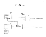
- graphics signal and an audio signal are previously stored by an external storage device 41 such as a floppy disk device, and an audio signal from a video disk player 42 and the graphics signal and audio signal from the external storage device 41 are supplied to a microcomputer 43 and processed, and the video signal from the video disk player 42 is mixed with the graphics signal in a MIX circuit 44 and outputted whereas the audio signal is mixed in the microcomputer 43 and outputted.
- the storage medium such as a floppy disk in the external storage device is small in its storage capacity, in order to increase the information content such as graphics image or audio, a plurality of record media are required.
- the maximum recording time of the video disk in the prior art is about one hour for a single side.
- the method of applying compression processing to the video signal and the audio signal regarding frequency band or time and then recording the processed signal and the method of improving the recording density of the record medium without the processing.
- a circuit of complicated constitution is required for the compression processing of the video signal, and particularly it cannot be easily realized from the aspect of the cost that the compression processing is performed while the quality of the video signal such as the NTSC system is maintained.
- the technical level to realize this method in practice has not yet been attained at present. Accordingly, it is not easy that the video signal and the audio signal in a plurality of channels are recorded on and reproduced from a single record medium without reducing the recording time.
- an object of the invention is to provide a recording and reproduction method and a reproduction apparatus, wherein video signals of a plurality of channels can be recorded on and reproduced from a single record medium easily without reducing the recording time, and graphics images can be added without using an external storage device exclusively.
- a recording method comprises the step of forming a first modulation signal carrying a composite video signal representing a composite screen image composed of reduced frames and corresponding to a plurality of channels, the step of forming a second modulation signal carrying a digital graphics signal and forming a frequency division multiplex signal by superimposing the first and second modulation signals onto each other and recording the multiplex signal on a record medium.
- a reproduction method comprises the step of designating at least one channel among the plurality of channels during reproduction, the step of extracting and demodulating the composite video signal and the graphics signal from the multiplex signal read from the record medium, and the step of substituting the obtained graphics signal for a portion of the display frame other than a reduced frame contained in the obtained composite video signal and corresponding to the designated channel.
- a reproduction apparatus of the invention for playing a record medium recorded as mentioned above comprises means for designating at least one channel among a plurality of channels, means for extracting and demodulating a composite video signal and a graphics signal from a multiplex signal read from the record medium, and means for substituting the obtained graphics signal for a portion of the display frame other than the reduced frame corresponding to the designated channel of the obtained composite video signal.
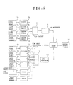
- video signals of channels A through D are outputted from video signal sources 1a through 1d such as video tape recorders.
- Each of the video signal sources 1a through 1d is constituted to output a composite video signal in synchronization with a synchronization signal outputted, for example, from a sync signal generator (not shown).
- Video signals of the channels A through D outputted from the video signal sources 1a through 1d are supplied to editing circuits 2a through 2d.
- Each of the editing circuits 2a through 2d reduces the supplied video signal into the size of 1/4 of one frame.
- a MIX circuit 3 is connected to the outputs of the editing circuits 2a through 2d.
- the MIX circuit 3 selectively inputs the output video signal of each of the editing circuits 2a through 2d in synchrony with output synchronization signals outputted, for example, from a sync signal generator (not shown) corresponding to a position on the 1H line, and prepares a composite video signal so as to form one frame.
- a single H-Line of the composite video signal issued from the MIX circuit 3 contains the video or picture signal from the circuit 1a at the first half portion thereof and the video signal from the circuit 1c at the second half portion thereof as long as the H-Line exists within an upper portion of a frame or field.
- the H-Line exists within a lower portion of a frame or field, it contains video signals from 1b and 1d at the first and second portions thereof.
- the composite video signal is formed so that portions "A" through "D" in one frame shown in Fig. 4 can be displayed at reduced areas of one screen of a displayer when the composite video signal is reproduced on the particular screen.
- the output of the MIX circuit 3 is supplied to an FM modulator 4.
- the FM modulator 4 the frequency of a carrier signal having a prescribed frequency is modulated and a video FM signal as a first modulation signal is formed.
- the video FM signal is supplied to an adder 5.
- audio signals of the channels A through D are outputted from audio signal sources 6a through 6d such as a tape recorder or the like.
- the audio signals of the channels A through D outputted from the audio signal sources 6a through 6d are supplied to audio time base compression and coding circuits 7a through 7d.
- the audio time base compression and coding circuits 7a through 7d generate digital data in response to sample values obtained, for example, by sampling the audio signal at a prescribed sampling frequency, and divide the digital data by using a reference timing signal outputted from a timing signal generator (not shown). They also perform blocking while adding a block code to each block, and output the data per each block at a transfer speed being four times that corresponding to the sampling frequency, and thus perform the time base compression per each block.
- the data blocks from circuit 7a through 7d are, for example, disposed within the subcode area of the so-called CD-I format.
- a graphic signal is outputted from a graphic data generating source 8 such as a microcomputer.
- an audio signal source 9 generates an audio signal having no direct relation to the channels A through D but including, for example, the operation explanation for users as its content.
- Each of the graphic signal and the audio signal is coded in the so-called CD-ROM or CD-I format in coders 10 and 11.
- the data issued from the coder 10 are graphic data disposed within the sub-code data.
- the data issued from the coder 11 are disposed within either one of the main-code and sub-code areas.
- Each data block of the audio time base compression and coding circuits 7a through 7d and the coders 10, 11 is supplied to an audio multiplexing circuit 12.
- the audio multiplexing circuit 12 selectively outputs each block of blocked data outputted from the audio time base compression circuits 7a through 7d, for example, by using the reference timing signal outputted from the timing signal generator (not shown) corresponding to the video block, or outputs the output data of either of the coders 10, 11.
- the output of the audio multiplexing circuit 12 is supplied to an EFM modulator 13 and converted into an EFM (Eight to Fourteen Modulation) signal as second and third modulation signals.
- the second modulation digital signal corresponds to output data issued from the coding circuit 10 and formulated into the sub-code data of the CD-ROM or CD-I format.
- the third modulation digital signal corresponds to output data issued from one of the circuits 7a through 7d and the coder 11 which are, for example, data blocks each having a sub-header formulated in the sub-code of the CD-I format.
- one "frame" in the CD-ROM or CD-I format signal includes a synchronous symbol (FS) of 24 bits, a sub-code symbol of 8 bits and 32 main code symbols of 256 bits, in sequence.
- FS synchronous symbol
- the FM video signal falls in the higher frequency region of 7.6 to 9.3 MHz and the EFM signal within a lower frequency region up to about 2 MHz.
- the output of the EFM modulator 13 is supplied to the adder 5 and added to the output of the FM modulator 4.
- the output of the adder 5 is supplied to a recording device 14.
- the recording device 14 is, for example, an optical video disk recorder as known well.
- the output of the adder 5 is supplied to an optical modulator, and a record track constituted by pits is formed, for example, on a recording surface of an original disk rotating at the frame period (e.g. 1/30 sec).
- Fig. 3 shows a reproduction apparatus for reproducing the video signal and the audio signal from a reproduction disk reproduced from the original disk obtained as above described.
- a disk 21 is driven for rotation by a motor (not shown) and a servo loop (not shown) in the frame period.
- the record information of the disk 21 is read by an optical pickup 22.
- the pickup 22 is provided with a laser diode, an actuator for focusing the light beam projected from the laser diode onto the recording surface of the disk, and an actuator for controlling the position of the focal point of the light beam in the radial direction of the disk.
- a servo loop is installed in the apparatus to control to drive the various sorts of actuators of the pickup 22. However, such a servo loop is not particularly required for the description and therefore omitted in the figure.
- control of the action of starting or stopping the pickup by a key operation is performed in an operation section such as a keyboard (not shown).
- the read output of the pickup 22 is supplied to a video signal demodulator 23 and a graphics data demodulator 24.
- the video signal demodulator 23 is constituted, for example, by a band pass filter for extracting the video FM signal component from the read output of the pickup 22 and an FM demodulator performing the demodulating processing of the output of the band pass filter.
- the data demodulator 24 is constituted, for example, by a low pass filter for extracting the audio EFM signal component from the read output of the pickup 22 and an EFM demodulator performing the demodulation processing of the output of the low pass filter.
- the video signal is demodulated by the video signal demodulator 23 and supplied to one input terminal of a signal changer 25.
- the output of an image memory 26 is connected to the other input terminal of the signal changer 25.
- a channel assignment code outputted from a channel assignment code generator 29 is supplied to an image processing control circuit 28.
- the channel assignment code generator 29 generates a code indicating the channel assigned or designated for example, by key operation of the operation section.
- the image processing control circuit 28 discriminates the channel area in 1H where the video signal of the channel assigned by the channel assignment code and the horizontal synchronous signal in the video signal is inserted, and performs the address control of the image memory 26 so that a video signal indicating a masking pattern carried by the digital graphic signal is written in the image memory 26 and then read out repeatedly at the disappearance of the particular channel area, and generates a changing command signal at starting of reading of the image memory 26.
- the video signal read from the image memory 26 is supplied to the other input terminal of the signal changer 25.
- the signal changer 25 selectively outputs one of the video signal outputted from the video signal demodulator 23 and the video signal read from the image memory 26 by the changing command signal outputted from the image processing control circuit 28.
- the output of the signal changer 25 is supplied to a video output terminal 30.
- the blocked data is demodulated by the data demodulator 24 and supplied to a buffer memory 31 and a block code reading circuit 32.
- the block code reading circuit 32 reads the block code in sequence, for example, in the blocked audio data and the graphic data.
- the block code outputted from the block code reading circuit 32 is supplied to a block processing control circuit 33.
- the channel assignment code outputted from the channel assignment code generator 29 is supplied to the block processing control circuit 33.
- the block processing control circuit 33 discriminates the block where the audio data or the graphic data of the channel assigned by the block code and the channel assignment code is inserted, and performs the address control of the buffer memory 31 so that the audio data or the graphic data of the corresponding block is written in the buffer memory 31 and then read out.
- the audio data read from the buffer memory 31 is that of the channel assigned by the channel assignment code
- the audio data is supplied to a time base expansion circuit 34.
- the time base expansion circuit 34 performs the time base expansion of the audio data four times for example.
- the audio data read from the buffer memory 31 is the coded data
- the audio data is supplied to an audio decoder 35 and decoded into an audio signal.
- the outputs of the time base expansion circuit 34 and the audio decoder 35 are mixed in a MIX circuit 36 and supplied to an audio output terminal 37.
- the graphic data is supplied to a graphic decoder 38.
- the coded graphic data is decoded into a graphics signal, which is supplied to the image memory 26.
- the signal changer 25 supplies the video signal from the video signal demodulator 23 to the video output terminal 30 only during the period that the video signal of the assigned channel among 1H is supplied. Consequently, when the assigned channel is the channel A, the image of the channel A is displayed to the left upward portion in the frame as shown in Fig. 5(A), and when the assigned channel is the channel B, the image of the channel B is displayed to the left downward portion in the frame as shown in Fig. 5(B), and when the assigned channel is the channel C, the image of the channel C is displayed to the right upward portion in the frame as shown in Fig. 5(C), and further when the assigned channel is the channel D, the image of the channel D is displayed to the right downward portion in the frame as shown in Fig. 5(D).
- the video signal including the graphic signal read from the image memory 26 is substituted for a portion other than the image portion (hatched portion in Fig. 5).
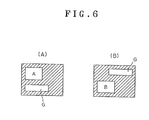
- the data of the image memory 26 is rewritten so that the graphic portion is not overlapped with the image portion of the assigned channel.
- the assigned channel is changed from the state of the channel A to the state of the channel B, if the graphics portion G in the frame in the state of the channel A shown in Fig. 6(A) is positioned to the left downward portion, at the changing to the state of the channel B, the graphics portion G in the frame in the state of the channel B shown in Fig. 6(B) is positioned to the right upward portion.
- a first modulation signal carrying a composite video signal representing a multiple frame constituted by small frames corresponding to a plurality of channels is formed, and a second modulation signal carrying the digital graphics signal is formed and the second modulation signal is frequency multiplexed to the first modulation signal so a multiplex signal is thereby formed and recorded to a record medium.
- a multiplex signal is thereby formed and recorded to a record medium.
- at least one channel among a plurality of channels is assigned, and the composite video signal and the graphics signal are extracted and demodulated from the multiplex signal read from the record medium, and the obtained graphics signal is substituted for a portion other than that corresponding to the assigned channel of the obtained composite video signal.
- the video information of the plurality of channels can be included in one video signal, i.e., track.
- the capacity of the record medium can be utilized effectively.
Landscapes
- Engineering & Computer Science (AREA)
- Multimedia (AREA)
- Signal Processing (AREA)
- Television Signal Processing For Recording (AREA)
- Signal Processing For Digital Recording And Reproducing (AREA)
Applications Claiming Priority (2)
| Application Number | Priority Date | Filing Date | Title |
|---|---|---|---|
| JP20039/90 | 1990-01-29 | ||
| JP2020039A JPH03224379A (ja) | 1990-01-29 | 1990-01-29 | 記録再生方法及び再生装置 |
Publications (1)
| Publication Number | Publication Date |
|---|---|
| EP0440408A1 true EP0440408A1 (de) | 1991-08-07 |
Family
ID=12015920
Family Applications (1)
| Application Number | Title | Priority Date | Filing Date |
|---|---|---|---|
| EP91300646A Withdrawn EP0440408A1 (de) | 1990-01-29 | 1991-01-29 | Verfahren und Gerät zur Aufzeichnung und Wiedergabe |
Country Status (3)
| Country | Link |
|---|---|
| US (1) | US5237426A (de) |
| EP (1) | EP0440408A1 (de) |
| JP (1) | JPH03224379A (de) |
Cited By (8)
| Publication number | Priority date | Publication date | Assignee | Title |
|---|---|---|---|---|
| EP0599607A1 (de) * | 1992-11-27 | 1994-06-01 | Matsushita Electric Industrial Co., Ltd. | System für die Zusammenstellung von Videodaten |
| EP0738078A3 (de) * | 1995-04-14 | 1996-12-11 | Toshiba Kk | Aufzeichnungsmedium, Datenaufzeichnungsverfahren und -vorrichtung sowie Datenwiedergabeverfahren und -vorrichtung dafür |
| EP0813344A3 (de) * | 1996-06-12 | 1998-01-07 | Kabushiki Kaisha Toshiba | Vielkanal-Aufnahme/Wiedergabevorrichtung |
| EP0836192A1 (de) * | 1993-10-29 | 1998-04-15 | Kabushiki Kaisha Toshiba | Aufzeichnungsmedium für Mehrfachszenen, und Verfahren und Vorrichtung zur Wiedergabe von Daten davon |
| US5835670A (en) | 1993-10-29 | 1998-11-10 | Kabushiki Kaisha Toshiba | Multilingual recording medium and reproduction apparatus |
| US5835669A (en) | 1995-06-28 | 1998-11-10 | Kabushiki Kaisha Toshiba | Multilingual recording medium which comprises frequency of use data/history data and a plurality of menus which are stored in a still picture format |
| CN1068450C (zh) * | 1995-04-14 | 2001-07-11 | 株式会社东芝 | 再生装置和再生方法 |
| US6357047B1 (en) | 1997-06-30 | 2002-03-12 | Avid Technology, Inc. | Media pipeline with multichannel video processing and playback |
Families Citing this family (8)
| Publication number | Priority date | Publication date | Assignee | Title |
|---|---|---|---|---|
| JPH0698291A (ja) * | 1992-09-11 | 1994-04-08 | Pioneer Electron Corp | アスペクト比情報を担うビデオディスク及びアスペクト比変換機能を有するビデオディスクプレーヤ |
| JPH0964770A (ja) | 1995-08-18 | 1997-03-07 | Matsushita Electric Ind Co Ltd | 地上放送及び衛星放送一体チューナ |
| EP0762756B1 (de) * | 1995-09-11 | 2002-03-06 | Matsushita Electric Industrial Co., Ltd. | Fernsehsignalaufnahme- und -wiedergabeanlage |
| US6430363B2 (en) * | 1995-09-11 | 2002-08-06 | Matsushita Electric Industrial Co., Ltd. | Video signal recording and reproducing apparatus |
| TW411451B (en) * | 1996-05-14 | 2000-11-11 | Toshiba Corp | Recording medium storing video data which can forcibly reproduce sub-video in accordance with reproducing state and its reproducing system |
| KR100238136B1 (ko) | 1996-11-28 | 2000-01-15 | 윤종용 | 디지털 비디오 재생장치 |
| KR100238668B1 (ko) * | 1996-11-28 | 2000-01-15 | 윤종용 | 디지털 비디오 재생장치 |
| US8326133B2 (en) | 2005-03-29 | 2012-12-04 | Koninklijke Philips Electronics N.V. | Method and device for providing multiple video pictures |
Citations (5)
| Publication number | Priority date | Publication date | Assignee | Title |
|---|---|---|---|---|
| GB1234439A (de) * | 1967-11-13 | 1971-06-03 | ||
| GB2096868A (en) * | 1981-04-09 | 1982-10-20 | Ampex | Audio/video editing system having touch responsive function display screen |
| DE3619799A1 (de) * | 1986-06-12 | 1987-12-17 | Gen Service Electronics Gmbh | Verfahren und vorrichtung zum mischen von videosignalen |
| EP0268270A2 (de) * | 1986-11-20 | 1988-05-25 | Matsushita Electric Industrial Co., Ltd. | Informationsschnittgerät |
| EP0339675A2 (de) * | 1988-04-28 | 1989-11-02 | Matsushita Electric Industrial Co., Ltd. | Fernsehempfänger und Verfahren zur Anzeige von Videoinformation |
Family Cites Families (4)
| Publication number | Priority date | Publication date | Assignee | Title |
|---|---|---|---|---|
| JPS58188307A (ja) * | 1982-04-27 | 1983-11-02 | Matsushita Electric Ind Co Ltd | 記録再生装置 |
| US5047868A (en) * | 1986-09-12 | 1991-09-10 | Hitachi, Ltd. | Image data processing method for selective partial image display |
| JP2620600B2 (ja) * | 1987-02-10 | 1997-06-18 | パイオニア株式会社 | マルチ画面表示方法 |
| US5016113A (en) * | 1988-04-04 | 1991-05-14 | Pioneer Electronic Corporation | Apparatus for reproducing and processing picture information including graphic codes from a recording medium |
-
1990
- 1990-01-29 JP JP2020039A patent/JPH03224379A/ja active Pending
-
1991
- 1991-01-29 US US07/648,318 patent/US5237426A/en not_active Expired - Fee Related
- 1991-01-29 EP EP91300646A patent/EP0440408A1/de not_active Withdrawn
Patent Citations (5)
| Publication number | Priority date | Publication date | Assignee | Title |
|---|---|---|---|---|
| GB1234439A (de) * | 1967-11-13 | 1971-06-03 | ||
| GB2096868A (en) * | 1981-04-09 | 1982-10-20 | Ampex | Audio/video editing system having touch responsive function display screen |
| DE3619799A1 (de) * | 1986-06-12 | 1987-12-17 | Gen Service Electronics Gmbh | Verfahren und vorrichtung zum mischen von videosignalen |
| EP0268270A2 (de) * | 1986-11-20 | 1988-05-25 | Matsushita Electric Industrial Co., Ltd. | Informationsschnittgerät |
| EP0339675A2 (de) * | 1988-04-28 | 1989-11-02 | Matsushita Electric Industrial Co., Ltd. | Fernsehempfänger und Verfahren zur Anzeige von Videoinformation |
Cited By (17)
| Publication number | Priority date | Publication date | Assignee | Title |
|---|---|---|---|---|
| EP0599607A1 (de) * | 1992-11-27 | 1994-06-01 | Matsushita Electric Industrial Co., Ltd. | System für die Zusammenstellung von Videodaten |
| US5526132A (en) * | 1992-11-27 | 1996-06-11 | Matsushita Electric Industrial Co., Ltd. | Image editing device with special effects using a recording medium in which two-channel reproduction and single-channel recording are simultaneously possible |
| US6128434A (en) | 1993-10-29 | 2000-10-03 | Kabushiki Kaisha Toshiba | Multilingual recording medium and reproduction apparatus |
| US5999695A (en) | 1993-10-29 | 1999-12-07 | Kabushiki Kaisha Toshiba | Multilingual recording medium and reproduction apparatus |
| EP0836192A1 (de) * | 1993-10-29 | 1998-04-15 | Kabushiki Kaisha Toshiba | Aufzeichnungsmedium für Mehrfachszenen, und Verfahren und Vorrichtung zur Wiedergabe von Daten davon |
| EP0836191A1 (de) * | 1993-10-29 | 1998-04-15 | Kabushiki Kaisha Toshiba | Verfahren und Vorrichtung zur Datenwiedergabe von einem Aufzeichnungsmedium |
| US5835670A (en) | 1993-10-29 | 1998-11-10 | Kabushiki Kaisha Toshiba | Multilingual recording medium and reproduction apparatus |
| US5963704A (en) * | 1995-04-14 | 1999-10-05 | Kabushiki Kaisha Toshiba | Recording medium, apparatus and method for recording data on the recording medium, apparatus and method for reproducing data from the recording medium |
| EP0738078A3 (de) * | 1995-04-14 | 1996-12-11 | Toshiba Kk | Aufzeichnungsmedium, Datenaufzeichnungsverfahren und -vorrichtung sowie Datenwiedergabeverfahren und -vorrichtung dafür |
| US6160952A (en) * | 1995-04-14 | 2000-12-12 | Kabushiki Kaisha Toshiba | Recording medium, apparatus and method for recording data on the recording medium, apparatus and method for reproducing data from the recording medium |
| CN1068450C (zh) * | 1995-04-14 | 2001-07-11 | 株式会社东芝 | 再生装置和再生方法 |
| CN1114212C (zh) * | 1995-04-14 | 2003-07-09 | 株式会社东芝 | 记录媒体的数据记录装置和方法以及数据再生装置和方法 |
| US5850500A (en) | 1995-06-28 | 1998-12-15 | Kabushiki Kaisha Toshiba | Recording medium comprising a plurality of different languages which are selectable independently of each other |
| US5835669A (en) | 1995-06-28 | 1998-11-10 | Kabushiki Kaisha Toshiba | Multilingual recording medium which comprises frequency of use data/history data and a plurality of menus which are stored in a still picture format |
| US6028979A (en) | 1995-06-28 | 2000-02-22 | Kabushiki Kaisha Toshiba | Multilingual recording medium and reproduction apparatus |
| EP0813344A3 (de) * | 1996-06-12 | 1998-01-07 | Kabushiki Kaisha Toshiba | Vielkanal-Aufnahme/Wiedergabevorrichtung |
| US6357047B1 (en) | 1997-06-30 | 2002-03-12 | Avid Technology, Inc. | Media pipeline with multichannel video processing and playback |
Also Published As
| Publication number | Publication date |
|---|---|
| US5237426A (en) | 1993-08-17 |
| JPH03224379A (ja) | 1991-10-03 |
Similar Documents
| Publication | Publication Date | Title |
|---|---|---|
| US5237426A (en) | Record regenerative method and regenerative apparatus | |
| US5130816A (en) | Method and apparatus for recording and reproducing information including plural channel audio signals | |
| JP4443578B2 (ja) | 情報担体 | |
| EP0330732A2 (de) | Verfahren und Gerät zur Aufzeichnung und Wiedergabe von Bildinformation mit Zusatzinformation zur Veränderung der wiedergegebenen Bildinformation | |
| US4920424A (en) | Method of recording and reproducing multi-channel information on and from recording medium | |
| EP0689364A3 (de) | Aufnahme und Wiedergabe von Bildsignalen | |
| ATE239295T1 (de) | Datenaufzeichnungsverfahren, -gerät und -medien sowie datenwiedergabeverfahren und -gerät | |
| CN1822173B (zh) | 信息记录装置和方法及录有记录控制程序的信息记录介质 | |
| EP0327751A2 (de) | Plattenspieler | |
| JP2003503811A (ja) | Dvd記録におけるデータ割り振り | |
| GB2233489A (en) | Digital video signal recording method and apparatus | |
| US5128775A (en) | Method for playing analog and digital video signals in a predetermined order from a composite disk | |
| US4970608A (en) | Editing system for rearranging allocation of information units on an information recording medium | |
| JPH05101541A (ja) | 再生専用記録媒体 | |
| US5177619A (en) | Apparatus for minimizing signal degradation during the copying of video signals from one recording medium to another recording medium | |
| EP0435289B1 (de) | Gerät zur Aufzeichnung von Videoplatten | |
| US5115323A (en) | Video disc apparatus recording time-expanded luminance signals and time-compressed chrominance signals | |
| JP2558474B2 (ja) | ダビング装置 | |
| JPH11134814A (ja) | 音声記録媒体および音声再生装置 | |
| JP3710525B2 (ja) | 画像装置 | |
| JPH0261860A (ja) | ビデオディスク再生装置 | |
| JPS61288580A (ja) | 静止画付音声信号記録再生方式 | |
| JPH04367178A (ja) | 磁気記録再生システム | |
| JP2689981B2 (ja) | 再生装置 | |
| JPS605472A (ja) | 情報記録再生装置 |
Legal Events
| Date | Code | Title | Description |
|---|---|---|---|
| PUAI | Public reference made under article 153(3) epc to a published international application that has entered the european phase |
Free format text: ORIGINAL CODE: 0009012 |
|
| AK | Designated contracting states |
Kind code of ref document: A1 Designated state(s): DE FR GB |
|
| 17P | Request for examination filed |
Effective date: 19911004 |
|
| 17Q | First examination report despatched |
Effective date: 19930820 |
|
| STAA | Information on the status of an ep patent application or granted ep patent |
Free format text: STATUS: THE APPLICATION IS DEEMED TO BE WITHDRAWN |
|
| 18D | Application deemed to be withdrawn |
Effective date: 19931231 |