EP0440812B1 - System und Vorrichtung für handschriftlich eingegebene Information - Google Patents
System und Vorrichtung für handschriftlich eingegebene Information Download PDFInfo
- Publication number
- EP0440812B1 EP0440812B1 EP90912462A EP90912462A EP0440812B1 EP 0440812 B1 EP0440812 B1 EP 0440812B1 EP 90912462 A EP90912462 A EP 90912462A EP 90912462 A EP90912462 A EP 90912462A EP 0440812 B1 EP0440812 B1 EP 0440812B1
- Authority
- EP
- European Patent Office
- Prior art keywords
- stroke
- handwritten
- unit
- area
- input
- Prior art date
- Legal status (The legal status is an assumption and is not a legal conclusion. Google has not performed a legal analysis and makes no representation as to the accuracy of the status listed.)
- Expired - Lifetime
Links
Images
















Classifications
-
- G—PHYSICS
- G06—COMPUTING OR CALCULATING; COUNTING
- G06F—ELECTRIC DIGITAL DATA PROCESSING
- G06F3/00—Input arrangements for transferring data to be processed into a form capable of being handled by the computer; Output arrangements for transferring data from processing unit to output unit, e.g. interface arrangements
- G06F3/01—Input arrangements or combined input and output arrangements for interaction between user and computer
- G06F3/048—Interaction techniques based on graphical user interfaces [GUI]
- G06F3/0487—Interaction techniques based on graphical user interfaces [GUI] using specific features provided by the input device, e.g. functions controlled by the rotation of a mouse with dual sensing arrangements, or of the nature of the input device, e.g. tap gestures based on pressure sensed by a digitiser
- G06F3/0488—Interaction techniques based on graphical user interfaces [GUI] using specific features provided by the input device, e.g. functions controlled by the rotation of a mouse with dual sensing arrangements, or of the nature of the input device, e.g. tap gestures based on pressure sensed by a digitiser using a touch-screen or digitiser, e.g. input of commands through traced gestures
- G06F3/04883—Interaction techniques based on graphical user interfaces [GUI] using specific features provided by the input device, e.g. functions controlled by the rotation of a mouse with dual sensing arrangements, or of the nature of the input device, e.g. tap gestures based on pressure sensed by a digitiser using a touch-screen or digitiser, e.g. input of commands through traced gestures for inputting data by handwriting, e.g. gesture or text
Definitions
- the invention relates to a handwritten input information processing apparatus and to a handwritten input information system.
- a handwritten input information processing apparatus and to a handwritten input information system.
- Such known apparatus and system are described in US-4 656 317.
- System and apparatus are capable of realizing a realistic sense of writing data on a paper with a pen, and are suitable for making a formatted document.
- a conventional handwritten input information processing apparatus realizing a realistic sense of writing data on a paper with a pen is disclosed, for example, in British Patent Laid-open Publication No. GB2193827A, Germany Patent Laid-open Publication Number DE3511353A1, Japanese Patent Laid-open Publication JP-A-63-184130, and SIG CHI, Volume 18, Number 2, (1989), pp. 73 to 74.
- a further conventional apparatus of the type that an operation description is designated at a particular area (icon, menu) on a CRT screen and the operation description is executed upon a click (switch-on or off) of a mouse, is disclosed in the Complete Hyper Card Handbook, Bantom Books Inc., Good man. D(1987).
- a formatted mail document shown in Fig. 2 is processed with a computer.
- the formatted mail document G100 shown in Fig. 2 is divided into areas G110 to G210. It is necessary for a computer to understand the contents entered in the receiver input area G130, transmitter input area G150, item input area G170, and contents input area G190, hence it is necessary to recognize a handwritten character stroke.
- An input to the receiver input area G130 is used as the information on a receiver to which this document is mailed.
- the information entered in the comment input area G210 is not necessary for the computer to process it, and it is sufficient if the contents written by the receiver is sent back to the transmitter. Therefore, a handwritten input stroke is not transformed into a clear form but it is used directly as a handwritten image comment.
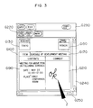
- a formatted mail document is to be formed by a computer using a conventional method, it is necessary as shown in Fig. 3 to enter a handwritting after designating the areas G220 and G230. For example, it is assumed that data is first handwritten in the transmitter area G150 and the comment area G210, and then this mail document is transferred. In this case, a user operates in the following manner.
- a conventional touch screen type format input apparatus has a hierarchic menu structure. Therefore, it has on one hand an advantage that data can be inputted by sequentially designating menus. However, on the other hand, it is associated with a problem that a form is limited to a particular one and data is required to be selected from menus so that it is difficult to deal with a variety of forms.
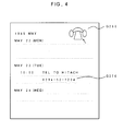
- Fig. 4 With an X windows tool kit or a HyperCard, as shown in Fig. 4, data is input through an interactive manner with a CRT screen upon a click of a mouse as a pointing input device. It is not possible to operate by contacting a pen directly with the screen, or to enter a character or graphics through handwriting. Thus, there is a problem of inability of interacting with the processing apparatus with a realistic sense of writing data on a paper with a pen.
- a conventional information processing apparatus has a size of a desk top or lap top apparatus so that it is not portable like a note book and cannot be used anywhere.
- Prior art document US-4 656 317 discloses a handwritten character input device. It comprises an input device for detecting handwritten information in specific areas on a tablet and a memory for storing such information according to the categories. Input areas are classified to be either name areas, date areas or price areas. Upon coordinate input there is checked whether the coordinates fall within one of these areas. If yes, certain measures are taken.
- a handwriting input unit made of an integral structure of a handwriting coordinate input device and a plane display is provided with a form defining unit for defining in advance the process operation for each area of the screen of the handwriting input unit, and a stroke interpretation executing unit for executing the process operation previously defined by the form defining unit when a handwritten stroke is entered in the area. Therefore, it is possible to realize a handwriting environment allowing to enter data with a realistic sense of writing data on a paper with a pen while understanding and executing an intent of a user.
- the characteristic features are that there are provided an operation description and its process environment capable of recognizing a handwritten stroke and converting it into a code of a character, graphics, line, or edit symbol, and that the screen of the handwriting input unit is divided into a plurality of areas to be recognized and not recognized, and an inputted handwritten stroke is converted into a predetermined code data or image data in correspondence with the data inputted area.
- the handwriting coordinate input device, a plane display, and their logic circuits constituting the information processing apparatus are mounted on a glass to form an integral structure thereof, thereby making the apparatus to have a size of a note or sheet having the thickness of the glass. Furthermore, a memory card is used as a file, and a battery and a wireless interface are used to make the apparatus motor-less and cord-less. Still further, the handwriting input unit, form defining unit, and stroke interpretation executing unit are configured on the assumption that a network is used.
- the handwriting input unit has an integral structure of its input and display sections so that the screen operation also represents an input operation, thereby realizing a realistic sense of writing data on a paper with a pen.
- the form defining unit first defines the layout of the screen of the handwriting input unit for a bill, mail document or the like. Next, basing upon this screen layout, an area is automatically set or changed to generate a plurality of significant areas. Then, an opration description is defined for each area as to what type of process operation is to be executed upon an input of a stroke.
- an inputted handwritten stroke is recognized as a character and it is displayed as a clear character in the one area, and in another area, the same character is displayed at a predetermined position.
- the handwritten stroke is also recognized as an edit symbol to edit a character under the edit symbol.
- a handwritten stroke is recognized as an image data of a handwritten comment.
- the operation description is defined by a dedicated handwriting descriptive language suitable for a handwriting process operation.
- the stroke interpretation executing unit calls a predetermined operation description in the corresponding area, to thereby interpret the handwritten stroke and execute the operation in accordance with the operation description.
- the form definition is defined only once unless the contents and layout thereof do not change. Therefore, a user only calls a necessary formatted document and directly enters a handwriting in a necessary position (area). Then, the processing unit interprets the meaning of the area and executes the operation, thereby realizing an environment which allows to understand an intent of the user and execute the operation.
- the input/output device and logic circuits are formed in an integral structure and mounted on a glass, and a file is stored in a removable memory card. Further, a battery and a wireless interface are provided to enable an access to a network whenever a user is located.
- the apparatus can thus be used freely at offices, during business trips, in trains, or at homes.
- a handwritten input information processing apparatus having a handwriting input unit made of an integral structure of a handwriting coordinate input device and a plane display, what type of a process operation is carried out for each area of the handwriting input unit is defined in advance.
- a handwriting is inputted, this is interpreted and the operation is carried out. Therefore, data can be entered with a realistic sense of writing data on a paper with a pen without intercepting human thinking processes, thereby considerably improving man-machine interface.
- the logic circuits of the handwritten input information processing apparatus are mounted on the glass of the handwriting input unit to make the apparatus as thin as a note or a sheet, and a battery and radio waves are used to make the apparatus cord-less. Therefore, the apparatus can be transported anywhere.
- a mechanism allowing to describe a recognition function to convert a hanwritten stroke into a code and a process function to use a network. Therefore, it is possible to configure an electronic secretary system supporting most of office transactions such as making documents, mails, telephones, FAXes, and electronic conferences.
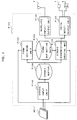
- Fig. 1 shows an system arrangement of the handwritten input information processing apparatus according to an embodiment of this invention.
- Fig. 2 is a diagram used for explaining the conventional operation of processing a formatted mail document by a computer.
- Fig. 3 is a diagram explaining the operation of making a formatted mail document using a computer by a conventional method.
- Fig. 4 illustrates a conventional HyperCard.
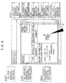
- Fig. 5 is a diagram used for explaining the operation of the embodiment of this invention shown in Fig. 1.
- Fig. 6 shows the structure of the overall system using the handwritten input information processing apparatus shown in Fig. 1.
- Fig. 7 is a cross section showing the hardware arrangement of the handwritten input information processing apparatus shown in Fig. 1.
- Fig. 8 is a cross section shwoing the hardware of the handwritten input information processing apparatus of Fig. 1 when it is configured for the purpose of presentation.
- Fig. 9 is a diagram in block form showing the logic circuits of the handwritten input information processing apparatus shown in Fig. 1.
- Fig. 10 shows an arrangement of the form defining unit shown in Fig. 1.
- Fig. 11 shows an arrangement of the stroke interpretation executing unit shown in Fig. 1.
- Figs. 12 and 13 are diagrams used for explaining the operation and function of the units shown in Figs. 10 and 11.
- Figs. 14 to 36 are flow charts, programs, and their operation illustrations of the system shown in Fig. 1.
- Figs. 37 to 38 show system arrangements of another embodiment of this invention wherein processing units including the handwriting input unit, form defining unit, and stroke interpretation executing unit are distributed over a network.
- Fig. 39 shows a system arrangement of another embodiment of this invention wherein a plurality of stroke input units are provided.
- Fig. 40 is a diagram used for explaining the stroke input unit shown in Fig. 39.
- Figs. 41 to 42 show an example of an operation description of the embodiment shown in Fig. 39, and an input area event map.
- Fig. 1 shows the system structure of a handwritten input information processing apparatus according to an embodiment of this invention.
- P100 represents the block diagram showing the system structure of this invention, the system being constructed of a processing apparatus such as a microcomputer.
- H211 represents a handwriting input hardware made of an integral structure of a handwriting coordiante input device and a plane display.
- P100 represents a stroke input unit for reading a coordinate data at the handwritten input hardware H211.
- T100 represents a stroke buffer for buffering the data read by the stroke input unit.
- P120 represents a format defining unit
- T200 represents generated format defining data
- P140 represents a stroke interpretation executing unit
- P130 represents a wireless input/output unit for realizing a cord-less system
- 9 represents an antenna
- P150 represents a sound input/output unit connected to a mcirophone 7 and a speaker 6 for realizing a telephone set.
- Coordiante data from the handwritten input hardware H211 is inputted to the stroke input unit P110 and temporarily stored in the stroke buffer T100.
- the stroke input unit P110 causes the handwritten input hardware H211 to display the handwritten data, thus providing a user with a realistic sense of writing data on a paper with a pen.
- the coordiante data in the stroke buffer T100 is sequentially read and processed by the format defining unit P120 and the stroke interpretation executing unit P140.
- the format defining unit is activated.
- the format defining unit P120 prepares for forming a formatted document using the editor function and cuts out and sets areas for the formatted document.
- UI/HAND-TALK a dedicated handwriting descriptive language
- the results of operation definition are filed as a format definition data T200. This format definition data can be accessed and used by the stroke interpretation executing unit P140 as many times as desired unless the format is changed.
- the stroke interpretation executing unit P140 is activated.
- the coordinate data in the stroke buffer T100 and the format definition data T200 defined for each area are read to analyze and execute a handwriting stroke.
- the results of the interpretation and execution can be displayed on the handwritten input hardware H211, can be used for information exchange with another processing apparatus via the wireless input/output unit P130, or can be used for telephone communication via the voice input/output unit P150.
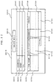
- Fig. 5 shows an example of a screen image of the embodiment of this invention, taking as an example the mail formatted document shown in Fig. 2 G110 to G250 represent the contents of operation description which are not usually displayed on the screen.
- "OBJ. Menu" at G220 indicates the name of program of operation description. The contents of each program operation description will be later detailed.
- the handwriting stroke is processed in accordance with the programmed description for that area. For example, in the item area at G170 and the contents area at G190, handwritten characters are recognized and clean characters thereof are displayed.
- the comment area at G210 a memo handwritten with a pen 2 is entered and the handwriting itself is displayed.
- data can be directly entered in an area with a realistic sense of writing data on a paper with a pen.
- Fig. 6 shows the overall system arrangement.
- Reference numerals 1 and 10 represent handwritten input information processing apparatuses
- reference numeral 2 represents a pen
- reference numeral 3 represents a screen of the handwritten input hardware H211 made of an integral combination of a handwriting coordiante input apparatus and a plane display
- reference numerals 4 and 5 represent memory cards
- reference numeral 6 represents a speaker
- reference numeral 7 represent a microphone
- reference nuemral 8 represents a handwritten data written with a pen
- reference numeral 9 represents an antenna built in the handwritten input information processing apparatus 1 for communication with a wireless terminal (WT) 12 using radio waves 20.
- WT wireless terminal
- Reference numerals 11 and 15 represent networks, reference numeral 11 represents a network connected to an ISDN (Integrated Services Digital Network) terminal 19, reference numeral 15 represents a LAN (Local Area Network) such as an Ethernet and a Token Ring connected to a workstation (WS) 16, a print server (PS) 17, and a file server (FS) 18.
- WS workstation
- PS print server
- FS file server
- the wireless terminals (WTs) 12 and 13 are connected to both the networks 11 and 15 which are accessible by the handwritten input information processing apparatuses 1 and 10.
- a facsimile (FAX) 14 is connected to the ISDN network.
- the handwritten input information processing apparatus 1 can operate by itself, or data may be shared with or distributed and processed by another information processing apparatus.
- the apparatuses 1 and 10 can be connected via radio waves with the wireless terminals (WTs) 12 and 13, thereby improving their operability. Further, since they can be connected to FAX, it is possible to send data inputted from the handwritten input information processing apparatus 1 on-line to another FAX via the ISDN network 22, or to have a mail exchange or an electronic conference between handwritten input information processing apparatuses via networks. It is possible to have an on-line electronic conference using voice and handwritten data, which is particularly useful for remote communication partners.
- WTs wireless terminals
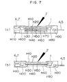
- Fig. 7 shows cross sections of hardware of handwritten input information processing apparatuses, wherein Fig. 7(a) is a cross section of an ordinary type handwritten input information processing apparatus, and Fig. 7(b) is a cross section of a presentation type handwritten input information processing apparatus.
- H10 represents a coordinate input glass on which a transparent electrode H20 for X-axis coordinate detection is coated.
- a transparent electrode H60 for Y-axis coordinate detection is coated on the bottom surface of a glass H50 which is also used for a liquid crystal display (LCD).
- Glasses for liquid crystal display are therefore glasses H30 and H50 between which liquid crystal H40 is provided.
- H80 and H100 represent logic circuits for processing a coordinate input and other operation for the processing apparatus 1, the logic circuits being implemented on the bottom surface of the coordinate input glass H10.
- This implementation is realized using the COG (Chip On Glass) technique whereby a bare chip is directly bonded on the glass at the position where there is no coordinate detection and display segment.
- COG Chip On Glass
- This technique is applied to mounting a driver IC for a liquid crystal display. Since an LSI bare chip is directly bonded on a glass, it is possible to realize a smaller and thinner device than using the surface mounting technique mainly used at present.
- the logic circuits H80 and H100 are bonded on the coordinate input glass H10. They may be bonded on the liquid crystal display glass H30 or H50.
- H70 represents an EL (ElectroLuminescence) for back light.
- H90 represents connectors of the memory cards 4 and 5
- H110 represents a battery of the processing apparatus 1.
- Reference numerals 6 and 7 represent a speaker and a microphone, respectively of a very thin type, which are used as a hand-free telephone set.
- the characteristic features of the processing apparatus reside in that the coordinate input device, display device, and logic devices are made of an integral structure, and that the processing apparatus is made thin.
- Fig. 7(b) shows a transparent type processing apparatus wherein a part of the bottom of the housing of this processing apparatus is cut off and the back light EL H70 is removed.
- light 27 from a light source lamp 25 of an OHP (Over Head Projector) indicated at 23 to 27 passes via a lens 24 through the processing apparatus so that an image on the processing apparatus is displayed via a mirror 26 on a screen.
- This processing apparatus is a so-called LCDOHP which is manufactured nowadays as a display device for a personal computer.
- the processing apparatus of this embodiment is suitable for the presentation purpose because it can be used as an LCDOHP and data can be handwritten with a pen 2 with a realistic sense of writing data on a transparent sheet with a felt pen. If a color LCD is used, a more effective presentation is possible.
- FIGs. 7(a) and 7(b) show discrete processing apparatuses, they may be constructed as a single processing apparatus having a structure selectable between Figs. 7(a) and 79b).
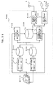
- Fig. 9 shows the hardware structure in block form of the logic circuits constituting the handwritten input information processing apparatus.
- H200 represents the overall structure in block form.
- H201 represents a microprocessor MPU
- H202 represents the bus line of MPU
- H203 represents a main memory
- H204 represents an LCD display memory
- H205 represents a card interface (I/F) for the memory cards 4 and 5
- H206 represents a wireless I/F
- H207 represents a coordinate input (TB) TB I/F
- H208 represents a drawing processor for developing an image on the display memory H204 and displaying it on LCD
- H209 represents a voice I/F for interface with the speaker 6 and the mcirophone 7
- H210 represents a KB I/F for an optional keyboard (KB) H212.
- the keyboard H212 is not required in an ordinary case, but it is connected to the processing apparatus when it becomes necessary for data input and program development.
- the antenna 9 is built in the housing 1 of the processing apparatus as described with Fig. 6. As particularly shown in Fig. 6, the antenna 9 is disposed at the upper area of the processing apparatus so as not to be influenced by a hand holding the pen 2 during handwriting or by other reasons.
- Fig. 10 shows the detailed system arrangement of the format defining unit 120 of the system shown in Fig. 1
- Fig. 11 is the detailed system arrangement of the stroke interpretation executing unit P140.
- P121 represents a stroke management unit
- P122 represents a screen defining unit
- P123 represents an operation defining unit
- P124 represents a UI/HAND-TALK language translator for translating source data T120 of the dedicated handwriting descriptive language UI/HAND-TALK.
- T110 represents a screen data processed by the screen defining unit P122
- T130 represents a module file of programs used by P122, P123, and P124, including a UI/HAND-TALK fundamental function, other application (AP) functions.
- AP application
- P141 represents a stroke management unit similar to P121.
- P142 represents a UI/HAND-TALK interpreter for reading the UI/HAND-TALK definition data T200 and interpreting and executing it.
- the embodiment of this invention relies on the assumption that there is used the dedicated handwriting descriptive language (UI/HAND-TALK).
- UI/HAND-TALK the dedicated handwriting descriptive language
- this language is a dedicated handwriting interpreter using the concept of object-oriented programming recently highlighted as a man-machine interface, which is characterized particularly in management and recognition of handwritten strokes.
- the form defining unit P120 shown in Fig. 10 will first be described.
- the form defining unit P120 is broadly divided into a screen definition and an operation definition the programs of which are selectively activated in accordance with the mode in a menu area MENU 2 shown in Figs. 12(a) and 12(b).
- Fig. 12(a) shows a screen of the screen defining mode.
- a submenu MENU 3 is displayed for defining the formatted document screen G100.
- a character input sheet G320 is displayed.
- the stroke is recognized as a character so that characters can be sequentially displayed at cursor positions on the sheet G100 as clear characters.
- This operation may be carried out by connecting an optional keyboard (KB) and using a kana-kanji conversion software.
- a "template” menu is used for improving the efficiency of screen definition by calling and pasting such a screen as a transmitter and a receiver, which screen is often used and stored along with its operation description.
- the screen defining unit 120 has the same function as a so-called screen editor.
- the operation defining unit P123 shown in Fig. 10 is activated by the stroke management unit P121 when an "operation definition" at the menu MENU 2 is designated as shown in Fig. 12(b).
- an operation description sheet G410 is displayed as shown in Fig. 12(b). The operation at the associated area is then described on this sheet.
- the operation description for entering a character is defined by using a "character input” or a "descriptive language" at the menu MENU 3.
- the descriptive data defined in the above manner is stored in the UI/HAND-TALK source file T120 shown in Fig. 10.
- the UI/HAND-TALK language translator P124 shown in Fig. 10 is activated to generate the UI/HAND-TALK definition data (intermediate data) T200 while referring to the files T120 and T130.
- each area of the screen G100 to be defined is automatically derived while referring to the screen data T110 when the screen defining unit P122 detects the "completion" at the menu MENU 3 shown in Fig. 12(a). If areas are to be edited, including re-setting an area and grouping areas (combining two or more areas as a single area), an "area" at the menu MENU 3 shown in Fig. 12(b) is designated.
- a "operation" at the menu MENU 2 is designated as shown in Fig. 12(c) after the screen definition and the operation definition have been completed, it becomes possible to enter an actual formatted document.
- a handwritten stroke directly entered on the item area G170.
- the stroke management unit P141 shown in Fig. 11 causes an "Object Item" defined at G410 in Fig. 12(b) to be activated. Since this program has the operation definition to recognize a handwritten input stroke as a character as described previously, handwritten strokes are sequentially recognized as characters and displayed as shown in Fig. 12(c).
- This process is carried out by the UI/HAND-TALK interpreter shown in Fig. 11 while referring to the files T200 and T130.
- the types of definition displays are illustrated in Fig. 33.
- the recognition function includes a "graphics recognition” for the recognition of a circle, rectangle, and the like, a “line recognition” for the recognition of an under line and the like, and an “edit symbol recognition” for the recognition of a red character edited with a red pen.
- a function using the network shown in Fig. 6 there are a “telephone” function, a “tele-writing” fucntion for use with electronic conference, and a "FAX" function.
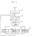
- Fig. 14 shows a main program of the processing apparatus.
- initialization is executed at step F100.
- the tables, UI/HAND-TALK interpreter, and screen are initialized.
- a data input process for the stroke buffer T100 is executed (step F200) to discriminate (step F300) between process modes of the menu MENU 2 described with Fig. 12.
- step F400 a screen definition process
- step F500 an operation definition process
- step F600 an operating process
- Fig. 15 is the detailed flow chart of the screen definition process (step F400).
- a suitable process is activated in accordance with the submenu MENU 3 (Fig. 12(a)).
- step F410 data is fetched from the stroke buffer (step F410) to discriminate the mode of the submenu (step F420) and activate one of a character input process (step F430), a drawing process (step F440), and a template process (step F450). If the "completion" is discriminated at the discrimination step (step F420) at the screen definition mode, this screen definition process is terminated after filing screen data (step F460).
- Fig. 16 is the detailed flow chart of the operation definition process (step F500).
- an automatic area deriving process is executed (step F510).
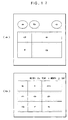
- Areas of a formatted document written on a paper are divided by boarder lines which are mainly straight lines. However, all areas are not necessarily divided according to this criterion. Examples of such a case and the area partitioning method will be explained next with reference to Fig. 17.
- FIG. 17(a) An example shown in Fig. 17(a) includes areas a to g , and an example shown in Fig. 17(b) includes areas h to s .
- Solid lines are those lines written on the document formats, and broken lines define derived areas. The area partitioning method will be described below.
- Areas a to c shown in Fig. 17(a) are closed areas of an ellipsoid frequently used for a destination name area.
- the closed areas are defined by a rectangular frame surroudning the ellipsoid.
- Areas d to g in Fig. 17(a) are also closed areas.
- the areas of the format can be partitioned.
- the method of searching a closed area there are a method of searching a closed area by scanning line data stored in the display memory shown in Fig. 9 one line after another, and a method of searching a closed area by sequentially tracing lines to find a smallest loop which is then separated as one closed area.
- Each area k , n , g , m, p , and s shown in Fig. 17(b) is called a U-character-shaped rectangular area having one side of the rectangle being removed. Such a form is often used for a table.
- the objects to be searched are blank character areas h , i , and j for year, month and day in Fig. 17(b).
- This blank character area can be separated by storing mapping coordinates of a character string when defining a character screen, and by searching the mapping coordinates and a blank code in the character string.
- a stroke buffer data input process is executed (step F520) to discriminate (step F530) between the operation definition modes at the submenu MENU 3 shown in Fig. 12(b).
- a proper process is activated (steps F540 and F570).
- the area process (F560) executes deletion or change of areas derived at step F510, addition of a new area, and a grouping process for a plurality of areas.
- the grouping process is a process for combining, e.g., two areas n and q shown in Fig. 17(b) into a single area.
- a set area is highlighted as necessary, e.g., by painting it out, coloring it, or displaying it with a dotted line, the described definition can be easily recognized.
- a UI/HAND-TALK language process (step F570) is executed to generate the UI/HAND-TANK definition data T200.
- This data is an intermediate code and interpreted and executed by the interpreter shown in Fig. 11.
- step F600 the working process shown in Fig. 14 will be described below with reference to Figs. 18 to 36.
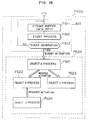
- Fig. 18 is a flow chart illustrating the operating process when actually using the already defined formatted document. This process is executed by using the above-described object-oriented programming scheme. The fundamental concept of this scheme will first be described, and then the contents of each operation description will be explained.
- step F610 concerns about an event process constituted by a stroke buffer input process (step F611), an event process (step F612), and an event occurrence judgment process (step F613).
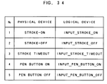
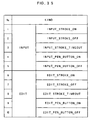
- a physical device may be arrnaged to be extended to a plurality of logical devices.
- a physical device is extended to two logical devices for an input device and for an edit device.
- Fig. 34 shows a correspondence of five physical devices and input logical devices. It is obvious that only the pen buttons may be assigned as edit pen buttons.
- a parameter of an event is described within the parentheses. If no parameter is described, a default is used.
- a feature number of coordinates when an event occurs is described.
- a feature number includes a start point, end point, gravity center point, and middle point, respectively of a stroke. For example, if the gravity center is selected, it is suitable for the input of a check mark. As the default, the stroke-on takes the start point, whereas the stroke-off takes the end point.
- a time at the timeout is described.
- the default is 2 seconds.
- the type number of a pen button is described. This button is usually mounted at the pen tip and corresponds to a mouse button. The number of buttons is one (left) or two (right and left). The default is (left).
- step F610 when an occurrence of an event described with Fig. 34 is detected, the coordinates at the time of the occurrence of the event are checked (the coordinates at the previous time for the stroke timeout and pen button) to activate an object at the area corresponding to the coordinates.
- the activated object checks the type of the event, and if there is any description in the object, the process is executed according to the description. If there is no description, the process is passed to an object at the lower area containing and superposing upon the activated object, i.e., in the example shown in Fig. 5, the sheet object G110.
- FIG. 18 it is assumed that an object A (object A ( )) has been activated.
- the object A executes the event process defined for its own, and wishes to request another object to execute some process. This request is conducted through message activation of the object-oriented programming.
- a message activation has the following format. SEND object name message name (parameter)
- the object name is the destination name
- the message name is a message name assigned to the destination object.
- objects are sequentially processed by means of event activation and message activation.
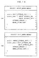
- Fig. 19 shows examples of an operation description of the menu object G220, wherein Fig. 19(a) illustrates an input menu object and Fig. 19(b) illustrates an edit menu object.
- Fig. 19(a) illustrates an input menu object
- Fig. 19(b) illustrates an edit menu object.
- Object is a reserved word representative of an object
- input-menu represents the name of an object
- (menu) represents a prototype of the object, namely, it means that the function and data structure of the object menu are inherited. It is advantageous in that if this inheritance function is used, a module structure having a new object or the like can be realized by generating a fundamental object and by adding a function thereto, " ⁇ " at the first line and “ ⁇ ” at the eighth line indicate the start and end of the object.
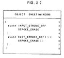
- Fig. 20 illustrates an operation description for a "sheet" object G110 shown in Fig. 5.
- the prototype of this object is a window.
- the operation description is used only for providing a blank sheet so that it describes to erase a handwritten stroke if inputted.
- Fig. 21 shows an example of an operation description of a receiver area object G130 shown in Fig. 5.
- a handwritten stroke is first recognized as a character, and a document is transferred to a mail destination represented by this recognized character code.
- Fig. 36 shows the kinds of handwritten stroke types which are broadly grouped into the following five kinds.
- Each stroke type is further classified into subtypes.
- the character stroke type in particular has as many as ten subtypes.
- handwritten strokes are used for various purposes.
- the kinds of strokes are limited in many cases, depending upon an area of a formatted document. For example, at the areas h, i, and j in the formatted document shown in Fig. 17(b), only numerals are permitted to use.
- the receiver area G130 shown in Fig. 5 only kanji of 1st standards, kanji of 2nd standards, hiragana, and katakana are permitted to use.
- Such a definition scheme for a stroke type and its recognition range designation is suitable for use in inputting data in a sales bill shown in Fig. 32.
- a specification area G720 often uses characters specific to the entered item name. If particular codes for that item name are declared in advance, it is possible to give an alarm display to a user when a character other than the declared characters is entered, thereby preventing possible erroneous character input.
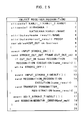
- Fig. 21 An example shown in Fig. 21 declares a parameter name_result as a NAME stroke type, and a parameter proof_result as a PROOF stroke type.
- the event (iii) is used for the description of correcting a receiver name using edit symbols.
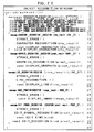
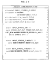
- Fig. 22 shows the operation description for a "recognition" object, including six messages.
- This object does not correspond to an area, but it is activated by a message from another object.
- the first message description at lines 3 to 11 message recognition execution (result:SSTYPE) ⁇ ⁇ is a program for this object.
- "STTYPE" at line 3 is a dummy stroke type.
- the stroke type is considered rather as an attribute data belonging to a parameter.
- STTYPE means that it is a dummy stroke type having no attribute and that the attribute of a real argument is inherited during execution.
- name_result stroke type is defined in advance as "NAME" at line 4 in Fig. 21, if the descriptions at lines 10 and 14 in Fig. 21 send recogniton recognition execution (name_result) are executed, "STTYPE" becomes the same stroke type as "NAME" because of type inheritance during execution.
- Fig. 23 illustrates a description of a "display" object activated by the object shown in Fig. 22.
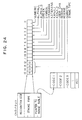
- send range check results are (cha_result, ok)
- cha_result is constructed, as shown in Fig. 24, of a recognition code (2 bytes), stroke type attribute (3 bytes), and range table pointer (2 bytes).
- the data structure of each of other stroke types is the same as above.
- the character range defined by the operation description is stored in the range table, so that the range can be checked from the code and the recognition code.
- Fig. 25 shows a description of a "transmitter" object at the area G150 shown in Fig. 5.
- Fig. 26 shows a description of an "item" object at the area G170 of Fig. 5.
- This object is used for entering a title of the item, and provides a description of recognizing a handwritten stroke as a character and displaying it or editing a character.
- the description contents can be easily inferred from the explanation given to the "receiver" object, so the explanation of the contents is omitted.
- Fig. 27 shows a description of a "contents" object at the area G190 of Fig. 5.
- This object provides a description for entering the particular contents of an item, the description including the character recognition and edit similar to the "item" object.
- the stroke type of the static parameter c_result is declared so as to allow an input of almost all types of characters shown in Fig. 36 (lines 1 to 5 in Fig. 27).
- Fig. 28 shows a description of the "comment" object at the area G210 in Fig. 5.
- a handwritten stroke is not recognized as a code, but is is used directly as an image. Therefore, in this object, the static parameter image_result is declared as a DOT stroke type so as to form a handwritten stroke as an image (line 1). This declaration is reflected to the description at line 5 to actually allow an input of a handwritten comment. A description for an image edit is also provided (lines 8 to 10).
- Fig. 29 shows a description of the "vertical scroll” object at the area G240 in Fig. 5.
- This "vertical scroll” object designates a prototype of "screen operation” to use this function for an actual scroll process. Specifically, upon input of a scroll in this area, an up- or scroll process is executed until the scroll is made off.
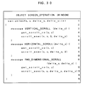
- the "screen operation" object is shown in Fig. 30.
- the description at line 4 get_scroll_co (x, y) is a function to check the current scroll position coordinates (x, y), and the description at line 5 scroll_exec (x, y, o, delta_y) is a function to execute an actual scroll.
- the delta_Y can be obtained from a function at line 4 in Fig. 29 get_delta_co (delta_x, delta_y).
- the "vertical scroll” object is defined to receive an event both in the input and edit modes.
- Fig. 31 shows an example of another description of the "receiver" object at the area G130 in Fig. 5. This description example is for dynamically changing the attribute of a particular area when a mail document is transferred to the receiver.
- attributes c_result:DOT.
- the handwriting input unit made of an integral structure of the handwriting coordinate input device and a plane display (LCD) is provided with a form defining unit for defining in advance the operation description for a handwritten stroke on the area unit basis, and a stroke interpretation executing unit for interpreting and executing the operation description defined for an area for which a handwritten stroke was entered. Therefore, the meaning of an entered handwritten stroke can be automatically interpreted by the apparatus, thereby providing a realistic sense of writing data on a paper with a pen, without intercepting human thinking processes and with a greatly improved man-machine interface capability.
- LCD plane display
- the second effect is as follows, it is possible to provide a description of a handwriting recognition function to recognize a handwritten stroke for each area and convert it into a code. Therefore, a system function of a network using mails, telephones, FAXes, electronic conferences, can be realized by means of handwritten strokes. As compared with a conventional point-to-point designation, office transactions can be easily simulated, and the embodiment handwritten input information system can support the roll of a secretary.
- the third effect is as follows.
- the form defining unit and the stroke interpretation executing unit can define the kind and recognition range of a handwritten stroke. Therefore, it becomes possible to improve the performance of recognition factor and prevent erroneous input. It is particularly suitable therefore for an input of a formatted bill document.
- the fourth effect is as follows.
- the processing apparatus automatically derives an area for the operation definition at the stage after the screen of a form has been defined. Therefore, a user is not required to set areas for the form, thereby improving the efficiency of form definition.
- the fifth effect is as follows. There is provided a mechanism capable of readily changing the process operation contents for a handwritten stroke at an area by changing only an attribute at the area concerned or at another area. Therefore, the flexibility and operability of form definition can be improved.
- the sixth effect is as follows.
- the input system of the handwriting input unit is interfaced via a stroke buffer with a function system of the stroke interpretation executing unit, separating the input system from the function system. Therefore, handwritten strokes can be sequentially entered without influence of the operation speed of the function system, alleviating a nervous temper of a user due to a delay of response.
- This processing apparatus is portable in nature because it is interfaced with a network via radio waves and contains a battery. Therefore, it can be used freely at offices, during business trips, or at homes.
- the eighth effect is as follows.
- the logic circuits of the processing apparatus are mounted on the glass of the handwriting input unit. Therefore, it can be thinned like a note or sheet.
- the ninth effect is as follows.
- the logic circuits of the processing apparatus are mounted at the periphery of the handwriting input unit. Therefore, it can be placed on an OHP to use it for presentations.
- Figs. 37 and 38 show system arrangements wherein the processing units of the system including a handwriting input unit, form defining unit, and stroke interpretation executing unit are distributed over a network.
- Fig. 37 shows a system arrangement wherein two processing units including a form defining unit P120 and a stroke interpretation executing unit P140 are connected to a workstation WS on a network to execute distributed processing, and only a processing unit of a handwriting input unit P110 is connected to the processing apparatus.
- the handwritten input information processing apparatus can be advantageously made compact and inexpensive since it has only the handwriting input unit and a man-machine interface unit for voices and the like.
- Fig. 38 shows a distributed system arrangement wherein processing units including a handwriting input unit P110-1 and a form defining unit P120 are connected to a handwritten input information processing unit P300, and processing units including a handwriting input unit P110-2 and an interpretation executing unit P140 are connected to another handwritten input information processing unit P400.
- processing units including a handwriting input unit P110-1 and a form defining unit P120 are connected to a handwritten input information processing unit P300
- processing units including a handwriting input unit P110-2 and an interpretation executing unit P140 are connected to another handwritten input information processing unit P400.
- a unit for defining a form and a unit for operating the defined from is separated, and they are operated by exchanging UI/HAND-TALK definition data.
- This definition data may be exchanged not via the network but by means of a memory card.
- the definition data of formatted documents can be managed at one place, thereby providing a simple management of documents. Furthermore, at the stage when meanaging the defined document, it is not necessary to provide an editor for use in defining handwritten forms, thereby reducing the system scale and making the apparatus inexpensive.
- Fig. 39 shows a system arrangement wherein a plurality of stroke input units are provided.
- the handwriting input unit is provided with first and second stroke input units P110 and P115.
- the first stroke input unit is used for an input of a stroke with one hand in the first embodiment of this invention
- the second stroke input unit is used for an input of a screen operation stroke with the other hand or a foot.
- a right-handed person having a pen with the right hand has a free left hand. Therefore, if the left hand is used for scroll operation or other basic menu operations, a more proper man-machine interface can be realized. For example, as shown in Fig. 40, if the left hand is pulled lower right on the second stroke input area, the screen G100 can be scrolled lower right.
- Fig. 41 shows an example of an operation description of a "scroll" object for the second stroke input area
- Fig. 42 is an event map for this input area.
- the operation description shown in Fig. 41 when an event of a screen operation stroke-on occurs, two-dimensional scroll continues to be executed until the screen operation stroke turns off.
- the description at line 5 send screen operation two-dimensional scroll (delta_x, (delta-y) is the message described in the "screen operation" object shown in Fig. 30.
- the second stroke input area is arranged so as not to overlap with the first stroke input area. These areas may be so arranged to overlap with each other. In such a case, the screen is caused to scroll right and left or up and down, with a hand moving along corresponding positions, thereby providing a more realistic sense of pulling a paper with a hand.
- both hands can be used for operating the handwritten input information apparatus, thereby considerably improving the man-machine performance.
- a change between an input mode and an edit mode has been designated with a menu.
- methods of changing a mode there are a method of changing a mode by means of a pen button, and a method of changing a mode in accordance with a stroke length which is characteristic information of a handwritten stroke.
- P120 and P140 shown in Fig. 1 have been assumed as an interpreter. This may be constructed of a compiler same as in the case of an ordinary programming language. However, a program is required to be compiled every time an operation description is changed.
- a physical device for a handwritten stroke has been extended to two input and edit logical devices. If a color display is used, colors may be changed with the kind of a logical device, further improving the operability. For example, if black is assigned to an input mode, and a read is assigned to an edit mode, a more realistic image of real paper and pen can be realized.
- Use of a color display can discriminate between areas to be recognized and not recognized, in accordance with colors, thereby making easier for a user to enter data.
- the handwriting coordiante input device and the plane display has been formed in an integrated structure. They may be formed separately. In this case, there is an inconvenience that both a hand and screen surface are to be observed repeatedly.
- the battery in the embodiment of this invention shown in Fig. 9 may be replaced with a solar battery.
- the coordinate input and display glass in the embodiment of this invention shown in Fig. 7 may be made of plastics material.
- a more realistic image of paper can be attained like a sheet computer or a paper computer, with further paper-less office environment.
Landscapes
- Engineering & Computer Science (AREA)
- General Engineering & Computer Science (AREA)
- Theoretical Computer Science (AREA)
- Human Computer Interaction (AREA)
- Physics & Mathematics (AREA)
- General Physics & Mathematics (AREA)
- Character Discrimination (AREA)
Claims (21)
- Vorrichtung (1, 10) zur Verarbeitung handschriftlich eingegebener Information miteiner Handschrifteneingabeeinheit (H211), die einen einheitlichen Aufbau aus einer Handschriftenkoordinateneingabeeinrichtung und einer ebenen Anzeige mit einem Bildschirm (3) mit zwei oder mehr Bereichen aufweist,einer Formdefinitionseinheit (P120), um vorab für jeden Bereich des Bildschirms eine Prozeßvorgangsbeschreibung so zu definieren, daß unterschiedliche Prozeßvorgangsbeschreibungen unterschiedlichen Bildschirmbereichen entsprechen, undeiner Zuginterpretationsausführungseinheit (P140), um dann, wenn ein Handschriftenzug in einen der Bildschirmbereiche eingegeben wird, die dem gewählten Zugeingabebereich entsprechende Prozeßvorgangsbeschreibung aufzurufen, um dadurch den eingegebenen Handschriftenzug zu interpretieren, und um einen Prozeßvorgang nach Maßgabe der aufgerufenen Prozeßvorgangsbeschreibung auszuführen.
- Vorrichtung nach Anspruch 1, bei der die Formdefinitionseinheit (P120) und die Zuginterpretationsausführungseinheit (P140) jeweils einen Handschriftenerkennungsprozeßvorgang beschreiben, um einen oder mehrere Handschriftenzüge in der Handschrifteneingabeeinheit (H211) als vorbestimmten Code zu erkennen, und den beschriebenen Prozeßvorgang ausführen.
- Vorrichtung nach Anspruch 1, bei der die Formdefinitionseinheit (P120) und die Zuginterpretationsausführungseinheit (P140) Merkmalsdaten für einen oder mehrere Handschriftenzüge in der Handschrifteneingabeeinheit (H211) herleiten und diese Merkmalsdaten als Information für die Prozeßvorgangsbeschreibung verwenden.
- Vorrichtung nach einem der Ansprüche 1 bis 3, bei der die Formdefinitionseinheit (P120) eine einen Bildschirm definierende Einheit aufweist, um eine Gestaltung des Bildschirms zu definieren, sowie eine Maßnahmendefinitionseinheit, um für einen Handschriftenzug für jeden durch die einen Bildschirm definierende Einheit beschriebenen Bereich einen Prozeßvorgang zu beschreiben.
- Vorrichtung nach Anspruch 4, bei der ein Gegenstandsbereich für die Vorgangsbeschreibung der Maßnahmendefinitionseinheit nach Maßgabe von Bildschirmdefinitionsdaten hergeleitet wird, die durch die Bildschirmdefinitionseinheit definiert wurden.
- Vorrichtung nach Anspruch 5, bei der nach Maßgabe von Linieninformation der Bildschirmdefinitionsdaten der Bereich hergeleitet wird als geschlossene Fläche oder als U-förmiger, rechtwinkliger Bereich, bei dem eine Seite eines geschlossenen Rechtecks entfernt wurde, oder ein Freizeichenbereich in einer Buchstabenfolge.
- Vorrichtung nach einem der Ansprüche 1 bis 3, bei dem die Formdefinitionseinheit (P120) und die Zuginterpretationseinheit (P140) jeweils eine Vorgangsbeschreibung aufweisen, um einen bestimmten Bereich dazu zu veranlassen, die Prozeßvorgangsinhalte eines Handschriftenzugs in einen bestimmten Bereich oder in mehreren bestimmten Bereichen zu ändern, und einen Ausführungsprozeß für die Vorgangsbeschreibung.
- Vorrichtung nach einem der Ansprüche 1 bis 3, bei der die Formdefinitionseinheit (P120) und die Zuginterpretationsausführungseinheit (P140) die Typen der Handschriftenzüge zumindest in Buchstabenzugtypen, Graphikzugtypen, Linienzugtypen, Bildzugtypen und Editierungszugtypen klassifizieren und eine Beschreibung zur Definition eines oder mehrerer der Typen sowie einen Ausführungsprozeß für die Beschreibungen aufweisen.
- Vorrichtung nach Anspruch 8, bei der der Buchstabenzugtyp, der Graphikzugtyp, der Linienzugtyp und der Editierungszugtyp jeweils eine Beschreibung zur Bestimmung eines Bereichs aufweisen, der für die Bestimmung eines oder mehrerer der Erkennungsgegenstandscodes zulässig ist, sowie einen Ausführungsprozeß für die Beschreibung.
- Vorrichtung nach Anspruch 9, bei der eine Alarmanzeige ausgeführt wird, wenn außerhalb des durch die Beschreibung angegebenen Bereichs ein Zug eingegeben wird.
- Vorrichtung nach einem der Ansprüche 1 bis 3, bei der die Zuginterpretationsausführungseinheit (P140) eine Einrichtung aufweist zum Anzeigen eines Umrisses der Vorgangsbeschreibungsinhalte, die für jeden Bereich durch einen bestimmten Vorgang definiert sind und Verwendung eines bildlichen Symbols.
- Vorrichtung nach Anspruch 8, bei der dann, wenn ein Zug vom Editierungszugtyp eingegeben wird, ein Code, der unter den Koordinaten des Zugs zu bearbeiten ist, unterschieden wird, wobei ein Bearbeitungsvorgang nach Maßgabe des Typs des Codes ausgeführt wird.
- Vorrichtung nach einem der Ansprüche 1 bis 3, bei der ein Handschrifteneingabeglas und ein Anzeigeglas als einheitliche Struktur gebildet sind, wobei eine Logikschaltung zumindest zum Erfassen der Koordinaten einer Handschrift und zum Verarbeiten eines eingegebenen Zuges direkt mit dem einheitlichen Glas verbunden ist.
- Vorrichtung nach Anspruch 13, bei der die Logikschaltung mit dem Rand des Glases verbunden ist, ohne ein Koordinatenerfassungssegment und ein Anzeigesegment zu überdekken.
- Vorrichtung nach einem der Ansprüche 1 bis 3, bei der das Vorgangssystem der Handschrifteneingabeeinheit (H211) unabhängig vom Vorgangssystem der Formdefinitionseinheit oder der Zuginterpretationsausführungseinheit (P140) arbeitet, wobei bevorzugt das Vorgangssystem der Handschrifteneingabeeinheit ausgeführt wird und beide Prozeßsysteme mit einem Zugpuffer verbunden sind.
- Vorrichtung nach einem der Ansprüche 1 bis 3, bei der die Handschrifteneingabeeinheit (F211) mehrere Koordinateneingabevorrichtungen aufweist.
- Vorrichtung nach Anspruch 16, bei der die Koordinateneingabevorrichtungen solche sind, die einen Eingabestift verwenden, und Vorrichtungen zum Eingeben eines Zugs auf direkte Berührung mit der Hand oder dem Fuß hin.
- System für handschriftlich eingegebene Information mit einer Informationsverarbeitungsvorrichtung (12) und einer Vorrichtung (1 - 9) zur Verarbeitung handschriftlich eingegebener Information, die eine Handschrifteneingabeeinheit (H211) hat, die einen einheitlichen Aufbau einer Handschriftenkoordinateneingabeeinheit und einer ebenen Anzeige mit einem Bildschirm (3) mit zwei oder mehr Bereichen hat, wobei die Informationsverarbeitungsvorrichtung (12, 13) und die Vorrichtung (1 - 9) zur Verarbeitung handschriftlich eingegebener Information über ein Netzwerk (11, 15) miteinander verbunden sind,wobei die Vorrichtung (1 - 9) zur Verarbeitung handschriftlich eingegebener Information zumindest die Handschrifteneingabeeinheit (H211) zum Eingeben eines Handschriftenzugs aufweist und eine Übertragungseinheit (9) zum Übertragen des Handschriftenzugs, der über die Handschrifteneingabeeinheit eingegeben wurde, über das Netzwerk an eine der Informationsverarbeitungsvorrichtungen, undwobei die Informationsverarbeitungsvorrichtung (12) zumindest eine Formdefinitionseinheit (P120) aufweist zum vorherigen Definieren einer Prozeßvorgangsbeschreibung für jeden Bereich des Bildschirms der Handschrifteneingabeeinheit, eine Zuginterpretationsausführungseinheit (P140), die dann, wenn in einen Bildschirmbereich ein Handschriftenzug eingegeben wird, die dem ausgewählten Zugeingabebereich entsprechende Prozeßvorgangsbeschreibung aufruft, um dadurch den eingegebenen Handschriftenzug zu interpretieren und einen Prozeßvorgang nach Maßgabe der aufgerufenen Prozeßvorgangsbeschreibung auszuführen, und eine Übertragungseinrichtung zum Übertragen von Daten über das Netzwerk an die Vorrichtung zum Verarbeiten handschriftlich eingegebener Informationen.
- System nach Anspruch 18, bei der die Handschrifteneingabeeinheit mehrere Koordinateneingabevorrichtungen aufweist.
- System nach Anspruch 19, bei der die Koordinateneingabevorrichtungen solche sind, die einen Eingabestift verwenden, und Vorrichtungen zum Eingeben eines Zuges auf die direkte Berührung mit einer Hand oder dem Fuß hin.
- System nach Anspruch 18, bei dem die Informationsverarbeitungsvorrichtung mit der Handschrifteneingabeeinheit mit einer anderen Informationsverarbeitungsvorrichtung über ein Local-Area-Network oder über ISDN verbunden ist und Vorgangsbeschreibungen aufweist, die Netzwerkquellen verwenden, und einen Ausführungsprozeß für die Vorgangsbeschreibung.
Applications Claiming Priority (4)
| Application Number | Priority Date | Filing Date | Title |
|---|---|---|---|
| JP1217360A JPH0381817A (ja) | 1989-08-25 | 1989-08-25 | 手書入力情報処理装置およびこの手書入力情報処理装置を用いた手書入力情報システム |
| JP21736089 | 1989-08-25 | ||
| JP217360/89 | 1989-08-25 | ||
| PCT/JP1990/001078 WO1991003013A1 (en) | 1989-08-25 | 1990-08-24 | Handwritten input data processor and handwritten input data system using the same |
Publications (3)
| Publication Number | Publication Date |
|---|---|
| EP0440812A1 EP0440812A1 (de) | 1991-08-14 |
| EP0440812A4 EP0440812A4 (en) | 1995-09-06 |
| EP0440812B1 true EP0440812B1 (de) | 1999-12-15 |
Family
ID=16702955
Family Applications (1)
| Application Number | Title | Priority Date | Filing Date |
|---|---|---|---|
| EP90912462A Expired - Lifetime EP0440812B1 (de) | 1989-08-25 | 1990-08-24 | System und Vorrichtung für handschriftlich eingegebene Information |
Country Status (6)
| Country | Link |
|---|---|
| US (1) | US5903667A (de) |
| EP (1) | EP0440812B1 (de) |
| JP (1) | JPH0381817A (de) |
| CA (1) | CA2039725C (de) |
| DE (1) | DE69033397T2 (de) |
| WO (1) | WO1991003013A1 (de) |
Families Citing this family (52)
| Publication number | Priority date | Publication date | Assignee | Title |
|---|---|---|---|---|
| US4856116A (en) * | 1988-07-07 | 1989-08-15 | Sullivan Lloyd S | Sweatbands |
| US5991440A (en) * | 1991-06-21 | 1999-11-23 | Canon Kabushiki Kaisha | Method and apparatus for recognizing input handwritten characters associated with title information |
| JP2986047B2 (ja) * | 1993-04-29 | 1999-12-06 | インターナショナル・ビジネス・マシーンズ・コーポレイション | ディジタル入力用表示装置並びに入力処理装置および方法 |
| AU684872B2 (en) * | 1994-03-10 | 1998-01-08 | Cable And Wireless Plc | Communication system |
| DE19534242A1 (de) * | 1995-09-17 | 1997-03-20 | Wolfgang Glaesker | Verfahren zum anwendungsoptimierten Betreiben eines tastaturlosen Personal-Computers |
| US6924790B1 (en) | 1995-10-16 | 2005-08-02 | Nec Corporation | Mode switching for pen-based computer systems |
| US6664982B1 (en) * | 1995-10-16 | 2003-12-16 | Nec Corporation | Multi-user on-screen keyboard |
| US6055333A (en) * | 1995-12-28 | 2000-04-25 | Motorola, Inc. | Handwriting recognition method and apparatus having multiple selectable dictionaries |
| US5970455A (en) * | 1997-03-20 | 1999-10-19 | Xerox Corporation | System for capturing and retrieving audio data and corresponding hand-written notes |
| US6292857B1 (en) * | 1997-06-05 | 2001-09-18 | Microsoft Corporation | Method and mechanism for coordinating input of asynchronous data |
| US6144764A (en) * | 1997-07-02 | 2000-11-07 | Mitsui High-Tec, Inc. | Method and apparatus for on-line handwritten input character recognition and recording medium for executing the method |
| JP2000284895A (ja) | 1999-03-31 | 2000-10-13 | Hitachi Software Eng Co Ltd | 座標入力ペン並びにそれを用いた電子ボード、座標入力システム及び電子ボードシステム |
| US6333994B1 (en) * | 1999-03-31 | 2001-12-25 | International Business Machines Corporation | Spatial sorting and formatting for handwriting recognition |
| US7721948B1 (en) * | 1999-05-25 | 2010-05-25 | Silverbrook Research Pty Ltd | Method and system for online payments |
| US20010033293A1 (en) * | 2000-02-16 | 2001-10-25 | Magnus Hollstrom | Electronic pen help feedback and information retrieval |
| US6813396B1 (en) | 2000-02-16 | 2004-11-02 | Telefonatiebolaget L.M. Ericsson (Publ) | Method for sharing information between electronic reading devices |
| US6839623B1 (en) | 2000-02-16 | 2005-01-04 | Telefonaktiebolaget Lm Ericsson (Publ) | Positioning applications for an electronic reading device |
| US6832116B1 (en) | 2000-02-16 | 2004-12-14 | Telefonaktiebolaget L M Ericsson (Publ) | Method and system for controlling an electronic utility device using an electronic reading device |
| US6885878B1 (en) * | 2000-02-16 | 2005-04-26 | Telefonaktiebolaget L M Ericsson (Publ) | Method and system for using an electronic reading device as a general application input and navigation interface |
| US6952497B1 (en) | 2000-02-16 | 2005-10-04 | Telefonaktiebolaget L M Ericsson (Publ) | Method and system for electronically recording transactions and performing security function |
| ATE265716T1 (de) * | 2000-02-16 | 2004-05-15 | Ericsson Telefon Ab L M | Stiftdrucker |
| US6864880B2 (en) * | 2000-03-21 | 2005-03-08 | Anoto Ab | Device and method for communication |
| KR100503167B1 (ko) * | 2000-08-04 | 2005-07-25 | 에이치. 김 리차드 | 다목적으로 조절할 수 있는 단일 시트 상자 |
| US6724936B1 (en) | 2000-08-23 | 2004-04-20 | Art-Advanced Recognition Technologies, Ltd. | Handwriting input device and method using a single character set |
| DE10043538B4 (de) * | 2000-09-05 | 2004-10-14 | Grundig Ag | Zusatzgerät zur Darstellung von Fernsehrundfunksignalen und Internetsignalen unter optimierten Benutzungsbedingungen |
| KR100417774B1 (ko) * | 2001-02-23 | 2004-02-14 | 박주현 | 컴퓨터내로 문자를 입력하는 장치 및 문자 인식방법 |
| US7571384B1 (en) * | 2001-05-31 | 2009-08-04 | Palmsource, Inc. | Method and system for handwriting recognition with scrolling input history and in-place editing |
| EP1302891A1 (de) * | 2001-10-12 | 2003-04-16 | Siemens Aktiengesellschaft | Vorrichtung zum Erfassen und Darstellen von Bewegungen |
| JP2003162687A (ja) * | 2001-11-28 | 2003-06-06 | Toshiba Corp | 手書き文字入力装置、手書き文字認識プログラム |
| US7343042B2 (en) * | 2002-09-30 | 2008-03-11 | Pitney Bowes Inc. | Method and system for identifying a paper form using a digital pen |
| US7167586B2 (en) * | 2002-09-30 | 2007-01-23 | Pitney Bowes Inc. | Method and system for remote form completion |
| US7417773B2 (en) * | 2002-09-30 | 2008-08-26 | Pitney Bowes Inc. | Method and system for creating and sending a facsimile using a digital pen |
| US7284200B2 (en) * | 2002-11-10 | 2007-10-16 | Microsoft Corporation | Organization of handwritten notes using handwritten titles |
| US7634729B2 (en) * | 2002-11-10 | 2009-12-15 | Microsoft Corporation | Handwritten file names |
| SE0401647D0 (sv) * | 2004-06-28 | 2004-06-28 | Anoto Ab | Coding and decoding of data |
| US8787706B2 (en) | 2005-03-18 | 2014-07-22 | The Invention Science Fund I, Llc | Acquisition of a user expression and an environment of the expression |
| US8340476B2 (en) * | 2005-03-18 | 2012-12-25 | The Invention Science Fund I, Llc | Electronic acquisition of a hand formed expression and a context of the expression |
| US8290313B2 (en) * | 2005-03-18 | 2012-10-16 | The Invention Science Fund I, Llc | Electronic acquisition of a hand formed expression and a context of the expression |
| US7809215B2 (en) | 2006-10-11 | 2010-10-05 | The Invention Science Fund I, Llc | Contextual information encoded in a formed expression |
| US7791593B2 (en) | 2005-03-18 | 2010-09-07 | The Invention Science Fund I, Llc | Machine-differentiatable identifiers having a commonly accepted meaning |
| US8102383B2 (en) | 2005-03-18 | 2012-01-24 | The Invention Science Fund I, Llc | Performing an action with respect to a hand-formed expression |
| US7873243B2 (en) | 2005-03-18 | 2011-01-18 | The Invention Science Fund I, Llc | Decoding digital information included in a hand-formed expression |
| US8599174B2 (en) | 2005-03-18 | 2013-12-03 | The Invention Science Fund I, Llc | Verifying a written expression |
| CN101198968B (zh) * | 2005-06-17 | 2010-05-19 | 阿诺托股份公司 | 用于组合位置和信息码的方法和系统 |
| JP2007080076A (ja) * | 2005-09-15 | 2007-03-29 | Fuji Xerox Co Ltd | 筆記内容記録システム及び筆記内容記録方法 |
| CA2633535A1 (en) * | 2005-10-25 | 2007-05-03 | Charactell Ltd. | Form data extraction without customization |
| US9648287B2 (en) * | 2007-02-15 | 2017-05-09 | Stewart Carl | Note capture device |
| WO2010086991A1 (ja) * | 2009-01-30 | 2010-08-05 | 富士通株式会社 | 画像表示装置、画像表示方法及びコンピュータプログラム |
| KR101658239B1 (ko) * | 2010-04-15 | 2016-09-30 | 삼성전자주식회사 | 애니메이션 메시지 생성 방법 및 장치 |
| FR2986459B1 (fr) | 2012-02-08 | 2015-12-18 | B Equipment | Procede et machine pour reduire la hauteur de boite a section carree ou rectangulaire |
| CN104350459B (zh) * | 2012-03-30 | 2017-08-04 | 诺基亚技术有限公司 | 用户接口、关联装置和方法 |
| US10546052B2 (en) * | 2015-10-12 | 2020-01-28 | Sugarcrm Inc. | Structured touch screen interface for mobile forms generation for customer relationship management (CRM) |
Family Cites Families (11)
| Publication number | Priority date | Publication date | Assignee | Title |
|---|---|---|---|---|
| EP0109581A3 (de) * | 1982-11-22 | 1985-04-24 | Allied Corporation | System zur Informationsfeld-Ortung auf einem Anzeigegerät und zur Feldbeschreibererzeugung mit Information, die mit jedem der Anzeigefelder verwandt ist |
| JPS60131041U (ja) * | 1984-02-08 | 1985-09-02 | シャープ株式会社 | 手書き入力情報の処理装置 |
| JPS6120120A (ja) * | 1984-07-06 | 1986-01-28 | Nippon Telegr & Teleph Corp <Ntt> | タツチパネル制御方式 |
| JPS61183730A (ja) * | 1985-02-08 | 1986-08-16 | Fujitsu Ltd | 複合通信端末装置 |
| JPH0785254B2 (ja) * | 1985-09-27 | 1995-09-13 | 株式会社東芝 | 文字画像読取装置 |
| US4972496A (en) * | 1986-07-25 | 1990-11-20 | Grid Systems Corporation | Handwritten keyboardless entry computer system |
| JPS6349822A (ja) * | 1986-08-20 | 1988-03-02 | Canon Inc | 会議用情報処理装置 |
| US4763356A (en) * | 1986-12-11 | 1988-08-09 | AT&T Information Systems, Inc. American Telephone and Telegraph Company | Touch screen form entry system |
| JPS63155386A (ja) * | 1986-12-19 | 1988-06-28 | Ricoh Co Ltd | 帳票デ−タ読取装置 |
| US5063600A (en) * | 1990-05-14 | 1991-11-05 | Norwood Donald D | Hybrid information management system for handwriting and text |
| US5134669A (en) * | 1990-06-13 | 1992-07-28 | National Computer Systems | Image processing system for documentary data |
-
1989
- 1989-08-25 JP JP1217360A patent/JPH0381817A/ja active Pending
-
1990
- 1990-08-24 EP EP90912462A patent/EP0440812B1/de not_active Expired - Lifetime
- 1990-08-24 CA CA002039725A patent/CA2039725C/en not_active Expired - Fee Related
- 1990-08-24 WO PCT/JP1990/001078 patent/WO1991003013A1/ja not_active Ceased
- 1990-08-24 DE DE69033397T patent/DE69033397T2/de not_active Expired - Fee Related
-
1993
- 1993-06-25 US US08/082,528 patent/US5903667A/en not_active Expired - Fee Related
Also Published As
| Publication number | Publication date |
|---|---|
| US5903667A (en) | 1999-05-11 |
| DE69033397T2 (de) | 2000-04-13 |
| WO1991003013A1 (en) | 1991-03-07 |
| EP0440812A1 (de) | 1991-08-14 |
| EP0440812A4 (en) | 1995-09-06 |
| CA2039725C (en) | 2001-01-16 |
| JPH0381817A (ja) | 1991-04-08 |
| CA2039725A1 (en) | 1991-02-26 |
| DE69033397D1 (de) | 2000-01-20 |
Similar Documents
| Publication | Publication Date | Title |
|---|---|---|
| US5903667A (en) | Handwritten input information processing apparatus and handwritten input information system using the same | |
| US5157384A (en) | Advanced user interface | |
| US5252951A (en) | Graphical user interface with gesture recognition in a multiapplication environment | |
| US6476834B1 (en) | Dynamic creation of selectable items on surfaces | |
| US11010027B2 (en) | Device, method, and graphical user interface for manipulating framed graphical objects | |
| CN1856796B (zh) | 基于铁笔的计算机系统和其用以接收用户通过铁笔和输入屏幕输入的手写信息的方法 | |
| US7533352B2 (en) | Method and apparatus for providing context menus on a hand-held device | |
| EP0379336B1 (de) | Anzeigegerät und Anzeigesystem mit einem solchen Gerät | |
| US6928619B2 (en) | Method and apparatus for managing input focus and z-order | |
| US6167439A (en) | Data retrieval, manipulation and transmission with facsimile images | |
| KR101424294B1 (ko) | 터치스크린 장치의 사용자로부터 수신된 입력 및 제스쳐에 응답하여 동작을 수행하는 컴퓨터로 구현된 방법 및 컴퓨터판독가능 매체 | |
| EP0150296A2 (de) | Verfahren und Vorrichtung für elektronische Handschrift | |
| US20040257346A1 (en) | Content selection and handling | |
| JP2003303047A (ja) | 画像入力及び表示システム、ユーザインタフェースの利用方法並びにコンピュータで使用可能な媒体を含む製品 | |
| US20100077304A1 (en) | Virtual Magnification with Interactive Panning | |
| US20250348210A1 (en) | Automatic Geometry Change of Graphic Objects in Response to User Indication | |
| Geiβler | Gedrics: the next generation of icons | |
| JP2000172428A (ja) | 情報処理装置及びそれを用いた情報システム | |
| US20060072009A1 (en) | Flexible interaction-based computer interfacing using visible artifacts | |
| WO2023159569A1 (zh) | 显示系统、轨迹点序列的处理方法、存储介质、设备 | |
| User | History of Pen and Gesture Computing: Annotated Bibliography in On-line Character Recognition, Pen Computing, Gesture User Interfaces and Tablet and Touch Computers | |
| HK1061586A1 (en) | Method for overlaying electronic ink on a document | |
| HK1061586B (en) | Method for overlaying electronic ink on a document |
Legal Events
| Date | Code | Title | Description |
|---|---|---|---|
| PUAI | Public reference made under article 153(3) epc to a published international application that has entered the european phase |
Free format text: ORIGINAL CODE: 0009012 |
|
| 17P | Request for examination filed |
Effective date: 19910506 |
|
| AK | Designated contracting states |
Kind code of ref document: A1 Designated state(s): DE FR GB IT NL |
|
| A4 | Supplementary search report drawn up and despatched | ||
| AK | Designated contracting states |
Kind code of ref document: A4 Designated state(s): DE FR GB IT NL |
|
| 17Q | First examination report despatched |
Effective date: 19960423 |
|
| GRAG | Despatch of communication of intention to grant |
Free format text: ORIGINAL CODE: EPIDOS AGRA |
|
| GRAG | Despatch of communication of intention to grant |
Free format text: ORIGINAL CODE: EPIDOS AGRA |
|
| GRAG | Despatch of communication of intention to grant |
Free format text: ORIGINAL CODE: EPIDOS AGRA |
|
| GRAH | Despatch of communication of intention to grant a patent |
Free format text: ORIGINAL CODE: EPIDOS IGRA |
|
| GRAH | Despatch of communication of intention to grant a patent |
Free format text: ORIGINAL CODE: EPIDOS IGRA |
|
| GRAA | (expected) grant |
Free format text: ORIGINAL CODE: 0009210 |
|
| AK | Designated contracting states |
Kind code of ref document: B1 Designated state(s): DE FR GB IT NL |
|
| PG25 | Lapsed in a contracting state [announced via postgrant information from national office to epo] |
Ref country code: NL Free format text: LAPSE BECAUSE OF FAILURE TO SUBMIT A TRANSLATION OF THE DESCRIPTION OR TO PAY THE FEE WITHIN THE PRESCRIBED TIME-LIMIT Effective date: 19991215 Ref country code: FR Free format text: LAPSE BECAUSE OF FAILURE TO SUBMIT A TRANSLATION OF THE DESCRIPTION OR TO PAY THE FEE WITHIN THE PRESCRIBED TIME-LIMIT Effective date: 19991215 |
|
| REF | Corresponds to: |
Ref document number: 69033397 Country of ref document: DE Date of ref document: 20000120 |
|
| ITF | It: translation for a ep patent filed | ||
| EN | Fr: translation not filed | ||
| NLV1 | Nl: lapsed or annulled due to failure to fulfill the requirements of art. 29p and 29m of the patents act | ||
| PG25 | Lapsed in a contracting state [announced via postgrant information from national office to epo] |
Ref country code: GB Free format text: LAPSE BECAUSE OF NON-PAYMENT OF DUE FEES Effective date: 20000824 |
|
| PLBE | No opposition filed within time limit |
Free format text: ORIGINAL CODE: 0009261 |
|
| STAA | Information on the status of an ep patent application or granted ep patent |
Free format text: STATUS: NO OPPOSITION FILED WITHIN TIME LIMIT |
|
| 26N | No opposition filed | ||
| GBPC | Gb: european patent ceased through non-payment of renewal fee |
Effective date: 20000824 |
|
| PG25 | Lapsed in a contracting state [announced via postgrant information from national office to epo] |
Ref country code: DE Free format text: LAPSE BECAUSE OF NON-PAYMENT OF DUE FEES Effective date: 20010501 |
|
| PG25 | Lapsed in a contracting state [announced via postgrant information from national office to epo] |
Ref country code: IT Free format text: LAPSE BECAUSE OF NON-PAYMENT OF DUE FEES;WARNING: LAPSES OF ITALIAN PATENTS WITH EFFECTIVE DATE BEFORE 2007 MAY HAVE OCCURRED AT ANY TIME BEFORE 2007. THE CORRECT EFFECTIVE DATE MAY BE DIFFERENT FROM THE ONE RECORDED. Effective date: 20050824 |