EP0440819B1 - Retroviseur de portiere retractable electriquement - Google Patents
Retroviseur de portiere retractable electriquement Download PDFInfo
- Publication number
- EP0440819B1 EP0440819B1 EP90912938A EP90912938A EP0440819B1 EP 0440819 B1 EP0440819 B1 EP 0440819B1 EP 90912938 A EP90912938 A EP 90912938A EP 90912938 A EP90912938 A EP 90912938A EP 0440819 B1 EP0440819 B1 EP 0440819B1
- Authority
- EP
- European Patent Office
- Prior art keywords
- gear
- stage worm
- shaft
- stage
- worm
- Prior art date
- Legal status (The legal status is an assumption and is not a legal conclusion. Google has not performed a legal analysis and makes no representation as to the accuracy of the status listed.)
- Expired - Lifetime
Links
- 230000007246 mechanism Effects 0.000 claims abstract description 52
- 230000009467 reduction Effects 0.000 claims abstract description 43
- 230000006835 compression Effects 0.000 claims description 5
- 238000007906 compression Methods 0.000 claims description 5
- 230000002452 interceptive effect Effects 0.000 abstract 1
- 238000005299 abrasion Methods 0.000 description 4
- 238000000034 method Methods 0.000 description 3
- 230000008569 process Effects 0.000 description 3
- 230000008901 benefit Effects 0.000 description 2
Images


Classifications
-
- B—PERFORMING OPERATIONS; TRANSPORTING
- B60—VEHICLES IN GENERAL
- B60R—VEHICLES, VEHICLE FITTINGS, OR VEHICLE PARTS, NOT OTHERWISE PROVIDED FOR
- B60R1/00—Optical viewing arrangements; Real-time viewing arrangements for drivers or passengers using optical image capturing systems, e.g. cameras or video systems specially adapted for use in or on vehicles
- B60R1/02—Rear-view mirror arrangements
- B60R1/06—Rear-view mirror arrangements mounted on vehicle exterior
- B60R1/062—Rear-view mirror arrangements mounted on vehicle exterior with remote control for adjusting position
- B60R1/07—Rear-view mirror arrangements mounted on vehicle exterior with remote control for adjusting position by electrically powered actuators
- B60R1/074—Rear-view mirror arrangements mounted on vehicle exterior with remote control for adjusting position by electrically powered actuators for retracting the mirror arrangements to a non-use position alongside the vehicle
-
- Y—GENERAL TAGGING OF NEW TECHNOLOGICAL DEVELOPMENTS; GENERAL TAGGING OF CROSS-SECTIONAL TECHNOLOGIES SPANNING OVER SEVERAL SECTIONS OF THE IPC; TECHNICAL SUBJECTS COVERED BY FORMER USPC CROSS-REFERENCE ART COLLECTIONS [XRACs] AND DIGESTS
- Y10—TECHNICAL SUBJECTS COVERED BY FORMER USPC
- Y10T—TECHNICAL SUBJECTS COVERED BY FORMER US CLASSIFICATION
- Y10T74/00—Machine element or mechanism
- Y10T74/18—Mechanical movements
- Y10T74/18568—Reciprocating or oscillating to or from alternating rotary
- Y10T74/18792—Reciprocating or oscillating to or from alternating rotary including worm
Definitions
- the present invention relates to a motor-driven foldable type door mirror used as mounted on the door of a car, and more particularly to a motor-driven foldable type door mirror of a compact design and a large reduction ratio, according to the preamble of claim 1.
- the motor-driven foldable type door mirror comprises a mirror base fixed to the door of a car, a shaft integrally formed on and extending from the mirror base, a mirror assembly pivotably supported on the shaft, a motor installed in the mirror assembly, and a reduction gear mechanism and clutch mechanism disposed between the motor and shaft.
- the mirror assembly is pivoted in relation to the mirror base from the normal to folded position or vice versa.
- an electrically-driven foldable body or door mirror comprising a mirror base to be fixed to the body or door of a car, a shaft extending from said mirror base, a mirror assembly including a unit bracket pivotably supported on said shaft, a motor provided in said mirror assembly, and a reduction gear mechanism including first-stage and second-stage worm gears disposed between said motor and shaft, each of said first-stage and second-stage worm gears containing a worm and a worm wheel, wherein said first-stage worm wheel is separate from said second-stage worm, said first-stage worm wheel and said second-stage worm are mounted non-rotatably with respect to each other on a rotating shaft of the second-stage worm.
- JP-A-62 52049 A disadvantage of JP-A-62 52049 is that the first-stage worm wheel or second-stage worm is influenced by the thrust load developed at the counterpart, namely, the second-stage worm or first-stage worm wheel, and it is not possible to prevent the speed-reduction efficiency of the reduction gear mechanism from being lowered due to the thrust load.
- the object of the present invention is to overcome the above problem.
- the present invention has the advantage of providing a motor-driven foldable type door mirror with no mutual interference between the reduction gear mechanism and the clutch mechanism and has a larger reduction ratio.
- the present invention provides an electrically-driven foldable body or door mirror which can be manufactured with a reduced quantity of necessary component parts in a reduced number of assembling processes.
- the reduction ratio can be further increased with no interference of the second-stage worm gear with the assembling of the clutch mechanism.
- balls for thrust bearings are preferably disposed between both ends of the rotating shaft of the second-stage worm of the reduction gear mechanism composed of the two stages of worm gears and the thrust gears which support both the ends of the rotating shaft of the second-stage worm, it is possible to minimize the abrasion, caused by the thrust load developed at the second-stage worm, of both the ends of the rotating shaft of the second-stage worm as well as of the thrust bearing bearing both the ends of the rotating shaft.
- the support holding both ends of the rotating shaft of the second-stage worm is preferably split, balls for thrust bearings can be interposed between the thrust bearings and both the ends of the rotating shaft of the second-stage worm.
- any thrust load developed at the first-stage worm wheel or at the second-stage worm has no influence on the counterpart, namely, the second-stage worm or the first-stage worm wheel and it is possible to prevent the speed-reduction efficiency of the reduction gear mechanism from being lowered due to the thrust load caused at the first-stage wheel or the second-stage worm.
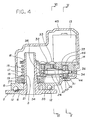
- the reference numeral 1 indicates a mirror base by which the mirror is fixed to the body of a car.
- the reference numeral 2 indicates a shaft holder on which a hollow shaft 3 is integrally formed, extending perpendicularly therefrom.
- the shaft holder 2 is fixed to the mirror base 1.
- the shaft 3 is chamfered at the reference numeral 4 against rotation, and has an engagement recess 5 provided circumferentially at the top end thereof.
- the shaft holder 2 has provided in the top face thereof concavities 6 in which balls 12 which will be described later are fitted, these concavities 6 being laid correspondingly to a normal position where the mirror is laterally projected from the car body and a folded position where the mirror is folded along the car body, respectively.
- the reference numeral 7 indicates a mirror assembly comprising a unit bracket 8 pivotably supported on the shaft 3, a mirror housing 9 and power unit 10 fixed to the unit bracket 8, and a mirror 11 so installed to the power unit 10 that it can be turned vertically and horizontally and which is disposed in the front opening of the mirror housing 9.
- Balls 12 are rotatably disposed at the bottom face of the unit bracket 8 at the positions opposite to the fitting concavities 6 in the mirror housing 9.
- the reference numeral 13 indicates a motor built in the mirror assembly 7 and installed on a plate 14 fixed to the unit bracket 8.
- the reference numeral 15 indicates a clutch mechanism mounted on the shaft 3 and which comprises a push nut 16, compression spring 17, washer 18, clutch gear 19 as input gear, clutch holder 20 and washer 21, as mounted on the shaft 3 sequentially from above.
- the clutch gear 19 is a spur gear and rotatable in relation to the shaft 3, and has an engagement recess 22 formed in the bottom thereof.
- the clutch holder 20 is fixed to the shaft 3, and has engagement pawls 23 provided on the top face thereof.
- the push nut 16 is engaged in the engagement recess 5 in the shaft 3 and compresses the compression spring 17.
- the engagement pawls 23 on the top face of the clutch holder 20 are engaged in the engagement recess 22 in the bottom face of the clutch gear 19 so that the clutch gear 19 is coupled with the clutch holder 20.
- the shaft holder 20 is forced upward by means of the shaft 3 so that the balls 12 on the unit bracket 8 are forced on the top face of the shaft holder 2.
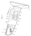
- the reference numeral 24 indicates a reduction gear mechanism disposed between the clutch mechanism 15 and the motor 13 and which comprises a first worm 25 fixed to the output shaft of the motor 13, a first helical gear 26, as first worm wheel, in mesh with the first worm 25, a second worm 27 having a rotating shaft 47 of which a D-cut portion is introduced axially movable but non-rotatably in a central through-hole 46 of the first helical gear 26, and a second helical gear 28, as second worm wheel, in mesh with the second worm 27.
- An output gear 29 of the spur gear is fixed concentrically to the second helical gear 28, and an idle gear 30 of the spur gear is interposed between the output gear 29 and the clutch gear 19 as input gear. Namely, the idle gear 30 is in mesh with the output gear 29 and the clutch gear 19 as input gear, respectively.
- the first worm 25 and first helical gear 26 as first worm wheel form together a first stage of worm gears
- the second worm 27 and second helical gear 28 as second worm wheel form a second stage of worm gears.
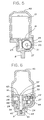
- the reference numeral 32 indicates a support separate from the plate 14. This support 32 is fixed to the plate 14 with a binding screw 33 and further fixed to the unit bracket 8 by means of the plate 14.
- a concavity 34 for thrust bearing is formed, and also a radial bearing 35 are provided, in the plate 14 and support 32. Both ends (one end between the first helical gear 26 and the second worm 26, and other end) of the rotating shaft 47 of the second worm 27 is rotatably born by the radial bearing 35 in the plate 14 and support 14, and balls 36 for thrust bearing are interposed between the concavity 34 for thrust bearing in the plate 14 and support 32 and both the end faces of the rotating shaft 47 of the second worm 27.
- the reference numeral 37 indicates a threaded shaft consisting of a head 38 at one end (top) thereof, a shaft portion 39 at the middle thereof, and a thread 40 at the other end (bottom) thereof.
- a screw hole 41 and head receiving concavity 42 are formed in the unit bracket 8 and plate 14, and there are provided an upper and lower bosses 43 between which the second helical gear 28 and output gear 29 are held.
- the shaft portion 39 of the threaded shaft 37 is inserted in a central hole 48 in the second helical gear 28 and output gear 29, the thread 40 of the threaded shaft 37 is screwed into a screw hole 41 in the unit bracket 8, and the head 38 of the threaded shaft 37 is engaged in the head receiving concavity 42 in the plate 14.
- the second helical gear 28 and output gear 29 are rotatably born on the shaft portion 39 of the threaded shaft 37 and fixed axially (in the thrust direction) between the boss 43 of the unit bracket 8 and the boss 43 of the plate 14, respectively.
- the plate 14 and support 32 are fixed to the unit bracket 8.
- the idle gear 30 is rotatably born on the unit bracket 8 by means of a rotating shaft (not shown). Also, the first worm 25 is rotatably born on the plate 14.
- the reference numeral 44 indicates a gear case provided on the unit bracket 8, and 45 indicates a lid installed as fitted on the top opening of the gear case 44.
- the lid 45 and gear case 44 enclose together the shaft 3, motor 13, clutch mechanism 15, reduction gear mechanism 24, etc.
- the motor-driven foldable type door mirror according to this embodiment is constructed as having been described in the foregoing. It is operated and functions as will be explained below: First, the motor 13 is put into operation. The rotation of the motor 13 is transmitted to the idle gear 30 by means of the two stages of worm gears and output gear 29. Since the clutch gear 19 as input gear is coupled with the clutch holder 20, the clutch holder 19 is stationary. When receiving the rotation from the motor 13, the idle gear 30 rotates itself while going around the clutch gear 19. As the idle gear 30 goes around the clutch gear 19, the mirror assembly 7 is pivoted in relation to the mirror base 1 from the normal position to the folded position or vice versa.
- the ball 12 at the mirror assembly 7 (unit bracket 8) is disengaged from the fitting concavity 6, and when the mirror assembly 7 is turned to the normal position or folded position, the ball 12 is fitted in the predetermined fitting concavity 6.
- the clutch gear 19 is uncoupled from the clutch holder 20 in the clutch mechanism 15 and the clutch gear 19 is rotated in relation to the shaft 3 while the mirror assembly 7 is pivoted from the normal position to the folded position or vice versa.
- the reduction gear mechanism composed of the two stages of worm gears is more compact and larger in reduction ratio than the conventional ones composed of spur gears.
- the output gear 29 is disposed at the worm gears in two stages at the reduction gear mechanism 24 while the clutch gear 19 as input gear is disposed at the clutch mechanism 15, and an idle gear 30 is disposed between, and in mesh with, the output gear 29 and clutch gear 19.
- This arrangement provides a further large reduction ratio.
- the idle gear 30 is interposed between the output gear 29 at the two stages of worm gears of the reduction gear mechanism 24 and the clutch gear 19, as input gear, of the clutch mechanism 15, the two stages of worm gears will not interfere with the assembling of the clutch mechanism 15. Namely, if the output gear 29 is put in direct mesh with the clutch gear 19 without using the idle gear 30, there will occur an interference between the second helical gear 28 of the reduction gear mechanism 24 and the clutch gear 19 of the clutch mechanism 15.
- the torque of the motor 13 is, for example, 365 g ⁇ cm and the reduction ratio of the first-stage worm gears (25 and 26) is 33 while that of the second-stage worm gears (27 and 28) is 30.
- the thrust load developped at the first helical gear 26 will be about 50 kg while that at the second worm 27 will be about 140 kg.
- the ball 36 for thrust bearing is interposed between both ends of the rotating shaft 47 of the second worm 27 in the reduction gear mechanism 24 and the concavity 34 for thrust bearing in the plate 14 and support 32, bearing together, the ends of the shaft 47.
- a thrust load develops at the second worm 27, it is received by the ball 36.
- the ball 36 for thrust bearing can be interposed between both ends of the rotating shaft 47 of the second worm 27 and the concavity 34 for thrust bearing in the plate 14 and support 34, supporting together the ends of the shaft 47.
- the first helical gear 16 is separate from the second worm 27 and the first helical gear 26 and second worm 27 are installed non-rotatably and axially movably (in the thrust direction).
- a thrust load developed at the first helical gear 26 or at the second worm 27 causes no influence-on the counterpart, namely, the second worm 27 or first helical gear 26, so that it is possible to prevent the speed reduction efficiency of the reduction gear mechanism 24 from being lowered due to the thrust load.
- the shaft portion 39 of the threaded shaft 37 is inserted in the central through-hole 48 through the second helical gear 28 and output gear 29, the thread 40 of the threaded shaft 37 is screwed into the screw hole 41 in the unit bracket 8, the head 38 of the threaded shaft 37 is engaged into the head receiving concavity 42 in the plate 14.
- the threaded shaft 37 serves as a rotating shaft for the second helical gear 28 and output gear 29, as a screw for fixing to the unit bracket 8 the plate 14 which supports the motor 13, first worm 25, first helical gear 26 and second worm 27, and as a member to connect the unit bracket 8 and plate 14 which support the thrust load developed at the second helical gear 28 and output gear 29.
- the first worm wheel 26 and second worm wheel 28 of the reduction gear mechanism 24 are a helical gear, but they may be a spur gear.
- the clutch mechanism 15 is disposed at the shaft 3, but it may be disposed at the reduction gear mechanism.
Landscapes
- Engineering & Computer Science (AREA)
- Multimedia (AREA)
- Mechanical Engineering (AREA)
- Rear-View Mirror Devices That Are Mounted On The Exterior Of The Vehicle (AREA)
Abstract
Claims (6)
- Rétroviseur de carrosserie ou de portière repliable entraîné électriquement et comprenant :
un pied de rétroviseur (1) à fixer à la carrosserie ou à une portière d'un véhicule automobile ;
un fût fixe (3) s'étendant à partir du pied (1) ;
un groupe rétroviseur (7) comprenant une console (8) supportée de façon à pouvoir pivoter sur le fût fixe (3) ;
un moteur (13) disposé dans le groupe rétroviseur (7) ; et
un mécanisme à engrenages démultiplicateurs (24) comprenant des engrenages à vis sans fin formant un premier étage et un second étage (25, 26 ; 27, 28) disposés entre le moteur (13) et le fût fixe (3), chacun des engrenages à vis sans fin formant respectivement le premier étage et le second étage contenant une vis sans fin (25 ; 27) et une roue à vis sans fin (26 ; 28),
rétroviseur dans lequel la roue à vis sans fin (26) du premier étage est séparée de la vis sans fin (27) du second étage, la roue à vis sans fin (26) du premier étage et la vis sans fin (27) du second étage sont montées de façon à ne pas pouvoir tourner l'une par rapport à l'autre sur un arbre rotatif (47) de la vis sans fin (27) du second étage,
caractérisé en ce que le fût fixe (3) est creux et est réalisé de façon à faire corps avec un porte-fût (2) et s'étend perpendiculairement à partir de ce dernier, le porte-fût (2) étant fixé au pied (1) du rétroviseur, et en ce que la roue à vis sans fin (26) du premier étage et la vis sans fin (27) du second étage sont montées de façon à être axialement déplaçables l'une par rapport à l'autre sur l'arbre rotatif (47). - Rétroviseur de carrosserie ou de portière repliable entraîné électriquement selon la revendication 1, comprenant en outre :
un pignon (29) fixé concentriquement à la roue à vis sans fin (28) du second étage dans le mécanisme à engrenages démultiplicateurs (24) accouplé au moteur (13) ;
un mécanisme d'embrayage (15) monté sur le fût fixe (3) ;
une roue dentée (19) disposée dans le mécanisme d'embrayage (15) ; et
un pignon fou (30) interposé entre la roue dentée (19) du mécanisme d'embrayage et le pignon (29) du mécanisme à engrenages démultiplicateurs (24). - Rétroviseur de carrosserie ou de portière repliable entraîné électriquement, selon la revendication 2, dans lequel le mécanisme d'embrayage (15) comprend un porte-embrayage (20) fixé au fût fixe (3), une roue dentée d'embrayage (19) montée de façon à pouvoir pivoter sur le fût fixe (3) et s'engrenant dans le pignon fou (30), et un ressort de compression (17) monté sur le fût fixe (3) pour tendre à pousser la roue dentée d'embrayage (19) en direction du porte-embrayage (20).
- Rétroviseur de carrosserie ou de portière repliable entraîné électriquement, selon la revendication 1, comprenant en outre :
un élément (14) pour retenir le mécanisme à engrenages démultiplicateurs (24) ; et
un arbre fileté (37) fixant l'élément de retenue (14) à la console (8) du rétroviseur monté (7), et portant la roue à vis sans fin (28) du second étage du mécanisme à engrenages démultiplicateurs (24) de façon que la roue (28) puisse tourner, et supportant en outre la poussée exercée au niveau de cette roue à vis sans fin (28) du second étage au moyen de l'organe de retenue et de la console (8). - Rétroviseur de carrosserie ou de portière repliable entraîné électriquement, selon la revendication 1, comprenant en outre :
un palier de butée supportant chaque extrémité de l'arbre rotatif (47) de la vis sans fin (27) du second étage du mécanisme à engrenages démultiplicateurs (24) ; et
une bille (36) interposée, pour chaque palier de butée, entre le palier de butée et chaque extrémité de l'arbre rotatif (47) de la vis sans fin (27) du second étage. - Rétroviseur de carrosserie ou de portière repliable entraîné électriquement, selon la revendication 5, dans lequel un support (32) pour les deux extrémités dé l'arbre rotatif (47) de la vis sans fin (27) du second étage est fendu de telle manière que les billes (36) pour les paliers de butée soient interposées entre les paliers de butée et les deux extrémités de l'arbre rotatif (47) de la vis sans fin (27) du second étage.
Applications Claiming Priority (9)
| Application Number | Priority Date | Filing Date | Title |
|---|---|---|---|
| JP101152/89U | 1989-08-31 | ||
| JP10115189U JPH0340251U (fr) | 1989-08-31 | 1989-08-31 | |
| JP10115289U JPH0340252U (fr) | 1989-08-31 | 1989-08-31 | |
| JP101153/89U | 1989-08-31 | ||
| JP10115089U JPH0340250U (fr) | 1989-08-31 | 1989-08-31 | |
| JP101150/89U | 1989-08-31 | ||
| JP101151/89U | 1989-08-31 | ||
| JP1989101153U JP2552109Y2 (ja) | 1989-08-31 | 1989-08-31 | 電動式ドアミラー |
| PCT/JP1990/001103 WO1991003390A1 (fr) | 1989-08-31 | 1990-08-30 | Retroviseur de portiere retractable electriquement |
Publications (3)
| Publication Number | Publication Date |
|---|---|
| EP0440819A1 EP0440819A1 (fr) | 1991-08-14 |
| EP0440819A4 EP0440819A4 (en) | 1992-05-20 |
| EP0440819B1 true EP0440819B1 (fr) | 1995-03-29 |
Family
ID=27468894
Family Applications (1)
| Application Number | Title | Priority Date | Filing Date |
|---|---|---|---|
| EP90912938A Expired - Lifetime EP0440819B1 (fr) | 1989-08-31 | 1990-08-30 | Retroviseur de portiere retractable electriquement |
Country Status (4)
| Country | Link |
|---|---|
| US (1) | US5172884A (fr) |
| EP (1) | EP0440819B1 (fr) |
| DE (1) | DE69018238T2 (fr) |
| WO (1) | WO1991003390A1 (fr) |
Families Citing this family (35)
| Publication number | Priority date | Publication date | Assignee | Title |
|---|---|---|---|---|
| DE4337750A1 (de) * | 1993-11-05 | 1995-05-11 | Bosch Gmbh Robert | Kraftfahrzeug-Außenrückspiegel |
| JP3008334U (ja) * | 1994-08-25 | 1995-03-14 | 株式会社村上開明堂 | 電動格納式ドアミラーの減速機構 |
| FR2723897B1 (fr) * | 1994-08-25 | 1998-04-10 | Murakami Kaimeido Kk | Reducteur de vitesse pour un retroviseur rabattable a commande electrique. |
| US5684646A (en) * | 1995-01-17 | 1997-11-04 | Lowell Engineering Corporation | Exterior mirror with single pivot power fold |
| NL1003144C2 (nl) * | 1996-05-15 | 1997-11-18 | Iku Holding Montfoort Bv | Elektrisch bedienbare scharnieractuator, en buitenspiegel met elektrisch bedienbaar scharniermechanisme. |
| EP0881124B1 (fr) * | 1997-05-29 | 2004-03-31 | Schefenacker Vision Systems Australia Pty Ltd | Mécanisme de commande pour un miroir rétroviseur |
| AUPP861999A0 (en) | 1999-02-09 | 1999-03-04 | Britax Rainsfords Pty Ltd | Mirror parking mechanism |
| JP2001069722A (ja) * | 1999-08-31 | 2001-03-16 | Jidosha Denki Kogyo Co Ltd | 開閉装置用回転検出センサ付モータ |
| CN1098781C (zh) * | 2000-04-07 | 2003-01-15 | 王振惠 | 电动后视镜自动折叠机构 |
| DE10042678C2 (de) * | 2000-08-31 | 2002-09-12 | Buhler Motor Gmbh | Vorrichtung zum Bewegen eines Körpers, insbesondere eines Fahrzeugteils und vorzugsweise eines Fahrzeugspiegels |
| JP3964627B2 (ja) * | 2001-03-19 | 2007-08-22 | 株式会社東海理化電機製作所 | 車両用ドアミラー装置 |
| DE60212745T2 (de) * | 2001-03-19 | 2006-11-02 | Kabushiki Kaisha Tokai Rika Denki Seisakusho | Kraftfahrzeugspiegelanordnung |
| DE10148611B4 (de) | 2001-10-02 | 2005-01-27 | Mekra Lang Gmbh & Co. Kg | Vorrichtung zum schwenkbeweglichen Lagern eines Tragarms für einen Aussenspiegel |
| EP1393974A1 (fr) * | 2002-08-29 | 2004-03-03 | MEKRA Lang GmbH & Co. KG | Rétroviseur extérieur pour véhicules utilitaires |
| JP4054252B2 (ja) * | 2002-12-04 | 2008-02-27 | 株式会社東海理化電機製作所 | 車両用ミラー装置及び車両用アウタミラー装置の格納機構 |
| JP4122993B2 (ja) * | 2003-02-04 | 2008-07-23 | 市光工業株式会社 | 電動格納式ドアミラー |
| JP4193785B2 (ja) | 2003-11-19 | 2008-12-10 | 市光工業株式会社 | 車両用電動格納装置の車両への取付方法及びこれに用いる車両用電動格納装置及びこの車両用電動格納装置が取り付けられた車両 |
| US7779728B2 (en) * | 2004-08-02 | 2010-08-24 | Flexsys, Inc. | Orienting arrangement for mirror or light source |
| CN100356492C (zh) * | 2005-03-23 | 2007-12-19 | 王光顺 | 储能式隔离开关 |
| JP4428340B2 (ja) | 2005-12-09 | 2010-03-10 | 市光工業株式会社 | 車両用ミラー装置 |
| JP2008087707A (ja) | 2006-10-04 | 2008-04-17 | Ichikoh Ind Ltd | 車両用アウトサイドミラー装置 |
| JP2008087706A (ja) * | 2006-10-04 | 2008-04-17 | Ichikoh Ind Ltd | 車両用アウトサイドミラー装置 |
| JP4807213B2 (ja) * | 2006-10-04 | 2011-11-02 | 市光工業株式会社 | 車両用アウトサイドミラー装置 |
| JP2008296719A (ja) * | 2007-05-31 | 2008-12-11 | Ichikoh Ind Ltd | 車両用アウトサイドミラー装置 |
| JP2008296721A (ja) * | 2007-05-31 | 2008-12-11 | Ichikoh Ind Ltd | 車両用アウトサイドミラー装置 |
| US9024581B2 (en) * | 2008-05-21 | 2015-05-05 | James W. McGinley | Charger plug with improved package |
| DE102009047130A1 (de) * | 2009-07-15 | 2011-02-03 | Robert Bosch Gmbh | Antriebseinrichtung eines Fahrzeug-Bauteils, insbesondere einer Karosserieklappe |
| DE102009055412A1 (de) | 2009-12-30 | 2011-07-07 | Robert Bosch GmbH, 70469 | Verstellantrieb mit integrierten Zusatzfunktionen |
| DE102010038596A1 (de) * | 2010-07-29 | 2012-02-02 | Robert Bosch Gmbh | Verstellantrieb mit integriertem Überlastschutz |
| DE102011083518A1 (de) * | 2011-09-27 | 2013-03-28 | Robert Bosch Gmbh | Verstellantrieb mit einem Getriebemotor mit Dauermagneten aus einem Seltenerdmetall |
| CN104590132B (zh) * | 2015-02-13 | 2017-04-26 | 宁波精成车业有限公司 | 汽车后视镜镜面驱动器双离合打滑装置 |
| DE102018108481B3 (de) | 2018-04-10 | 2019-02-28 | Dr. Ing. H.C. F. Porsche Aktiengesellschaft | Stellantrieb für einen Heckspoiler eines Kraftfahrzeugs |
| DE102019115163B3 (de) * | 2019-06-05 | 2020-09-10 | Motherson Innovations Company Limited | Anklappaktuator mit rastenbetätigtem Antrieb, Rückblicksystem und Fahrzeug |
| CN114179897B (zh) * | 2021-12-20 | 2023-03-07 | 延锋国际座椅系统有限公司 | 一种折叠方向盘 |
| EP4238827B1 (fr) * | 2022-03-04 | 2025-01-22 | Ficomirrors, S.A. | Ensemble couvercle d'actionneur pliable |
Citations (1)
| Publication number | Priority date | Publication date | Assignee | Title |
|---|---|---|---|---|
| DE3013009A1 (de) * | 1980-04-03 | 1981-10-08 | Gustav Magenwirth Gmbh & Co, 7432 Urach | Vorrichtung zum antrieb eines kraftfahrzeugspiegels |
Family Cites Families (6)
| Publication number | Priority date | Publication date | Assignee | Title |
|---|---|---|---|---|
| US2219367A (en) * | 1939-06-01 | 1940-10-29 | Johnson Spencer | Flush tank |
| JPS5687651U (fr) * | 1979-12-07 | 1981-07-14 | ||
| JPS6250249A (ja) * | 1985-08-28 | 1987-03-04 | Mitsui Mining & Smelting Co Ltd | 車両用ミラ−装置 |
| US4919526A (en) * | 1987-10-27 | 1990-04-24 | Ichikoh Industries Ltd. | Electrically swingable door mirror |
| JPH0649956Y2 (ja) * | 1988-03-04 | 1994-12-14 | マブチモーター株式会社 | ウオーム減速機付小型モータ |
| US4798967A (en) * | 1988-03-24 | 1989-01-17 | Murakami Kaimeido Co | Control system for foldable outside rearview mirror |
-
1990
- 1990-08-30 EP EP90912938A patent/EP0440819B1/fr not_active Expired - Lifetime
- 1990-08-30 DE DE69018238T patent/DE69018238T2/de not_active Expired - Fee Related
- 1990-08-30 WO PCT/JP1990/001103 patent/WO1991003390A1/fr not_active Ceased
- 1990-08-30 US US07/674,337 patent/US5172884A/en not_active Expired - Lifetime
Patent Citations (1)
| Publication number | Priority date | Publication date | Assignee | Title |
|---|---|---|---|---|
| DE3013009A1 (de) * | 1980-04-03 | 1981-10-08 | Gustav Magenwirth Gmbh & Co, 7432 Urach | Vorrichtung zum antrieb eines kraftfahrzeugspiegels |
Also Published As
| Publication number | Publication date |
|---|---|
| DE69018238D1 (de) | 1995-05-04 |
| DE69018238T2 (de) | 1995-07-27 |
| EP0440819A1 (fr) | 1991-08-14 |
| EP0440819A4 (en) | 1992-05-20 |
| US5172884A (en) | 1992-12-22 |
| WO1991003390A1 (fr) | 1991-03-21 |
Similar Documents
| Publication | Publication Date | Title |
|---|---|---|
| US5172884A (en) | Motor-driven foldable type door mirror | |
| US4645159A (en) | Powered seat adjusting device | |
| EP0519115B1 (fr) | Rétroviseur extérieur rabattable | |
| US5636071A (en) | Speed reduction device for an electrically powered foldable rearview mirror | |
| EP0686524A1 (fr) | Dispositif de positionnement du boîtier de miroir pour rétroviseur de véhicule, | |
| US4884844A (en) | Double stage taumel gear reduction unit | |
| EP0587994B1 (fr) | Rétroviseur extérieur repliable électriquement pour véhicules automobiles | |
| EP1275558B1 (fr) | Réducteur de vitesse et rétroviseur électrique escamotable de véhicule avec ce réducteur | |
| KR100363629B1 (ko) | 이동액튜에이터 | |
| US7008067B2 (en) | Electrically operable pivoting actuator for door mirror of motor vehicle | |
| EP0169245A1 (fr) | Retroviseur lateral commande a distance pour vehicule automobile | |
| CA2226645A1 (fr) | Ensemble serrure a vis motorisee | |
| JPH03121946A (ja) | 回動装置のトルクリミッタ機構 | |
| CA2179198A1 (fr) | Ensemble rail pour dispositif de reglage actionne par moteur de siege de vehicule | |
| JPH07110597B2 (ja) | 電動格納型ドアミラ− | |
| US4257192A (en) | Window regulator and drive assembly | |
| WO1991004172A1 (fr) | Mecanisme pivotant pour logement de retroviseur de vehicule | |
| US5321590A (en) | Headlight adjusting device | |
| JPS6382844A (ja) | 車両用ミラ−装置 | |
| CN115123101B (zh) | 一种屏幕多角度摆动机构 | |
| US4611501A (en) | Remote control apparatus | |
| JP3129957B2 (ja) | アクチュエータの出力軸 | |
| JP2552040Y2 (ja) | 電動格納式ドアミラー | |
| US5046379A (en) | Remote control apparatus | |
| CA1263266A (fr) | Telecommande |
Legal Events
| Date | Code | Title | Description |
|---|---|---|---|
| PUAI | Public reference made under article 153(3) epc to a published international application that has entered the european phase |
Free format text: ORIGINAL CODE: 0009012 |
|
| 17P | Request for examination filed |
Effective date: 19910426 |
|
| AK | Designated contracting states |
Kind code of ref document: A1 Designated state(s): DE FR GB |
|
| A4 | Supplementary search report drawn up and despatched |
Effective date: 19920331 |
|
| AK | Designated contracting states |
Kind code of ref document: A4 Designated state(s): DE FR GB |
|
| 17Q | First examination report despatched |
Effective date: 19920710 |
|
| GRAA | (expected) grant |
Free format text: ORIGINAL CODE: 0009210 |
|
| AK | Designated contracting states |
Kind code of ref document: B1 Designated state(s): DE FR GB |
|
| ET | Fr: translation filed | ||
| REF | Corresponds to: |
Ref document number: 69018238 Country of ref document: DE Date of ref document: 19950504 |
|
| PLBE | No opposition filed within time limit |
Free format text: ORIGINAL CODE: 0009261 |
|
| STAA | Information on the status of an ep patent application or granted ep patent |
Free format text: STATUS: NO OPPOSITION FILED WITHIN TIME LIMIT |
|
| 26N | No opposition filed | ||
| REG | Reference to a national code |
Ref country code: GB Ref legal event code: IF02 |
|
| PGFP | Annual fee paid to national office [announced via postgrant information from national office to epo] |
Ref country code: FR Payment date: 20060808 Year of fee payment: 17 |
|
| PGFP | Annual fee paid to national office [announced via postgrant information from national office to epo] |
Ref country code: GB Payment date: 20060830 Year of fee payment: 17 |
|
| GBPC | Gb: european patent ceased through non-payment of renewal fee |
Effective date: 20070830 |
|
| REG | Reference to a national code |
Ref country code: FR Ref legal event code: ST Effective date: 20080430 |
|
| PG25 | Lapsed in a contracting state [announced via postgrant information from national office to epo] |
Ref country code: FR Free format text: LAPSE BECAUSE OF NON-PAYMENT OF DUE FEES Effective date: 20070831 |
|
| PGFP | Annual fee paid to national office [announced via postgrant information from national office to epo] |
Ref country code: DE Payment date: 20080912 Year of fee payment: 19 |
|
| PG25 | Lapsed in a contracting state [announced via postgrant information from national office to epo] |
Ref country code: GB Free format text: LAPSE BECAUSE OF NON-PAYMENT OF DUE FEES Effective date: 20070830 |
|
| PG25 | Lapsed in a contracting state [announced via postgrant information from national office to epo] |
Ref country code: DE Free format text: LAPSE BECAUSE OF NON-PAYMENT OF DUE FEES Effective date: 20100302 |