EP0440820B1 - Dispositif de commutation de plages de mesures automatique pour appareil de mesure de superficie - Google Patents
Dispositif de commutation de plages de mesures automatique pour appareil de mesure de superficie Download PDFInfo
- Publication number
- EP0440820B1 EP0440820B1 EP90912947A EP90912947A EP0440820B1 EP 0440820 B1 EP0440820 B1 EP 0440820B1 EP 90912947 A EP90912947 A EP 90912947A EP 90912947 A EP90912947 A EP 90912947A EP 0440820 B1 EP0440820 B1 EP 0440820B1
- Authority
- EP
- European Patent Office
- Prior art keywords
- signal
- gain
- gases
- amplifier
- circuit means
- Prior art date
- Legal status (The legal status is an assumption and is not a legal conclusion. Google has not performed a legal analysis and makes no representation as to the accuracy of the status listed.)
- Expired - Lifetime
Links
Images


Classifications
-
- G—PHYSICS
- G01—MEASURING; TESTING
- G01N—INVESTIGATING OR ANALYSING MATERIALS BY DETERMINING THEIR CHEMICAL OR PHYSICAL PROPERTIES
- G01N15/00—Investigating characteristics of particles; Investigating permeability, pore-volume or surface-area of porous materials
- G01N15/08—Investigating permeability, pore-volume, or surface area of porous materials
- G01N15/088—Investigating volume, surface area, size or distribution of pores; Porosimetry
- G01N15/0893—Investigating volume, surface area, size or distribution of pores; Porosimetry by measuring weight or volume of sorbed fluid, e.g. B.E.T. method
Definitions
- the invention relates to a surface area measuring device according to the preamble of claim 1.
- a conventional surface area measuring device has a sample cell 2 mounted detachably in a gas passage 1 which has means A for measuring a flow rate of supply gases to be supplied for measuring a flow rate of measuring gases to the sample cell 2 and means B for measuring a flow rate of discharge gases for measuring an amount of gases discharged from the sample cell 2.
- a signal G1 for detecting an amount of supply gases generated from the means A for measuring the flow rate of the supply gases and a signal G2 for detecting an amount of discharge gases generated from the means B for measuring the amount of the discharge gases are inputted into an amplifier 3, and the amplifier 3 subtracts the signal G1 for detecting the amount of the supply gases and the signal G2 for detecting the amount of the discharge gases and generates an amplified differential signal G3.
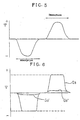
- the signal G2 for detecting the amount of the discharge gases becomes usually smaller than the signal G1 for detecting the amount of the supply gases when the measuring gases are adsorbed on the sample in the sample cell 2 under a cold state, so that the differential signal G3 to be generated from the amplifier 3 is outputted as a negative signal as shown in Fig. 5.
- the magnitude of the negative differential signal G3 is proportional to the magnitude of the amount of the gases to be adsorbed on the sample.
- the negative differential signal G3 is returned to zero. Thereafter, the cooling of the sample cell 2 is suspended to return the sample cell 2 to ambient temperature. As a result, the gases adsorbed on the sample start desorbing.
- the differential signal G3 becomes an increasing positive signal and the magnitude of the differential signal G3 decreases as the desorption gets finished. And the differential signal G3 is returned to zero as the desorption of the gases has been finished.
- the surface area is calculated by integrating the positive differential signals G3 by means of an arithmetic processing unit 4 in a period of time for desorption of the gases and the calculation result is displayed on the display unit 5 and generated.
- Such conventional surface area measuring devices of this kind have a switch 6 for shifting gains and the gains of the amplifier 3 are shifted manually.
- the gain of the amplifier 3 is shifted manually to a low level, thereby preventing the positive differential signal G3 from reaching the set gain of the amplifier 3 in a period of time for desorption.
- the gain of the amplifier 3 is not shifted, the positive differential signal G3 has reached the set gain of the amplifier 3 in the period of time for desorption, too, as shown in Fig. 6, and the amount of gases desorbed cannot be accurately calculated by integrating the positive differential signals G3.
- the gain of the amplifier 3 should be shifted to a gain of a high level because the surface area cannot accurately be calculated even by integrating minute differential signals G3".
- the object of the present invention is to provide a system for shifting a measuring range of a surface area measuring device so arranged as to be capable of automatically shifting the gain of the amplifier so as to allow the differential signal to reach no set gain of the amplifier during a period of time for desorbing gases, in order to accurately calculate the surface area.
- the surface area measuring device is characterized by the features of claim 1.
- the US-A 3 211 006 discloses a continuous flow method and apparatus for determining absorption isotherms of solid material.
- the differential signal outputted from the amplifier is outputted to the output value determining circuit during a period of time for adsorbing gases.
- the output value determining circuit generates a signal for reducing a level of the gain for altering the gain of the amplifier to a low level by comparing the set gain or cutoff value of the amplifier with the differential signal to be inputted, while generating the signal for reducing the level of the gain to the shift switch for shifting the level of the gain, when it is detected that the differential signal reaches zero from a negative value.
- the output value determining circuit monitors to determine if the differential signal has a constant output during a predetermined period of time.
- the differential signal monitors to determine if the differential signal exceeds 50% of the gain, and it generates a signal for increasing the level of the gain when the differential signal does not exceed 50% of the gain while it outputs the signal for increasing the level of the gain to a switch for shifting the level of the gain.
- the differential signal does not always exceed the gain of the amplifier during a period of time for desorbing gases and the differential signal does not become too small with respect to the gain of the amplifier, so that the surface area can accurately be calculated by integraing the differential signals.
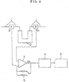
- Fig. 1 is a circuit diagram showing an embodiment according to the present invention.
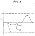
- Fig. 2 is a graph showing a wave form indicating the action of the present invention.
- Fig. 3 is a circuit diagram showing an example of the structure of the output value determining circuit in the aforesaid embodiment of the present invention.
- Fig. 4 is a circuit diagram showing a conventional device.
- Fig. 5 is a graph showing a wave form indicating a state of signals generated from the amplifier when measuring gases are adsorbed on a sample in the sample cell and when the measuring gases adsorbed are desorbed.
- Fig. 6 is a graph showing a wave form indicating a signal to be outputted from the amplifier for a conventional device.
- the surface area measuring device is such that a sample cell 11 is detachably connected to a passage 10 for measuring gases, means for measuring a flow rate of supply gases, i.e. a first gas flow meter A of thermal conductivity type, which generates the signal G1 for detecting an amount of supply gases by measuring a flow rate of the supply gases to be supplied to the sample cell 11, is disposed in the gas passage 10 for the measuring gases, and means for measuring a flow rate of discharge gases, i.e. a second gas flow meter B of thermal conductivity type, which generates the signal G2 for detecting an amount of discharge gases by measuring a flow rate of the discharge gases to be discharged from the sample cell 11, is disposed in the gas passage 10 for the measuring gases.
- This surface area measuring device further has an amplifier AMP, a shift switch SW for shifting gains of the amplifier, an output value determining circuit 12, arithmetic means 13, and a display unit 14.
- the amplifier AMP is so arranged as to receive the signal G1 for detecting the amount of supply gases to be generated from the first gas flow meter A of thermally conductive type and the signal G2 for detecting the amount of discharge gases to be generated from the second gas flow meter B of thermally conductive type, to subtract one signal from the other signal, and to amplify and generate the differential signal G3.
- the shift switch SW for shifting the gains of the amplifier AMP is so arranged as to automatically shift the gains of the amplifier AMP between a high level RH and a low level RL in response to a shift signal G4 to be generated from the output value determining circuit 12.
- the output value determining circuit 12 comprises a circuit 12a for generating a signal for lowering the level of a gain, a circuit 12b for generating a signal for detecting a zero level, a circuit 12c for generating a signal for expanding the level of a gain, a first AND circuit 12d, a second AND circuit 12e, and an OR circuit 12f.
- the circuit 12a for generating the signal for lowering the level of the gain is so arranged as to receive the differential signal G3 to be outputted from the amplifier AMP, to compare the differential signal G3 with the set gain of the amplifier AMP, and to generate and output a signal GL for lowering the level of the gain when the differential signal G3 agrees with the set gain of the amplifier AMP.
- the circuit 12b for generating the signal for detecting the zero level is so arranged as to receive the differential signal G3, to detect the time at which the differential signal G3 turns from its negative value to zero, and to output a signal Go for detecting the zero level.
- the circuit 12c for generating the signal for expanding the level of the gain is so arranged as to receive the differential signal G3, to compare the differential signal G3 with a reference value predetermined with respect to the set gain, i.e. 50% of the set gain, and to detect that the differential signal G3 does not reach 50% of the set gain for a predetermined period of time, thereby outputting a signal GH for expanding the level of the gain.
- the first AND circuit 12d is to perform AND operation between the signal GL for lowering the level of the gain and the signal Go for detecting the zero level.
- the second AND circuit 12e is to perform AND operation between the signal GH for expanding the level of the gain and the signal Go for detecting the zero level.
- the OR circuit 12f is to perform OR operation between the signal outputted from the first AND circuit 12d and the signal outputted from the second AND circuit 12e.
- the arithmetic unit 13 is so arranged as to calculate the surface area of a sample by integrating the differential signals G3 during the period of time for desorption of the gases, a differential signal being outputted from the amplifier AMP.
- the arithmetic unit 13 may be composed of a CPU.
- the display unit 14 is a printer or a CRT unit for outputting or displaying data from the arithmetic unit 13.
- the differential signal G3 to be outputted from the amplifier AMP is a negative signal as shown in Fig. 2.
- This negative signal is inputted into the output value determining circuit 12 which in turn is so arranged as to allow the negative differential signal G3 to be inputted into the circuit 12a for generating the signal G3 for lowering the level of the gain, the circuit 12b for generating the signal Go for detecting the zero level and the circuit 12c for generating the signal GH for expanding the level of the gain.
- the differential signal G3 is a signal which exceeds the gain
- the signal GL for lowering the level of the gain is outputted from the circuit 12a for generating the signal for lowering the level of the gain.
- the signal GL for lowering the level of the gain is inputted into the first AND circuit 12d.
- the differential signal G3 to be outputted from the amplifier AMP increases from the negative value to the zero level and, as the measuring gases are adsorbed on the sample to a saturated extent, the differential signal G3 is turned to the zero level.
- the circuit 12b for generating the signal for detecting the zero level disposed in the output value determining circuit 12 detects the zero level to which the differential signal G3 has reached and generates the signal Go for detecting the zero level.
- the signal Go for detecting the zero level is outputted into the first AND circuit 12d which in turn outputs the signal GL for lowering the level of the gain through the OR circuit to the shift switch SW for shifting the gain of the amplifier AMP, in response to the signal Go for detecting the zero level, thereby lowering the gain of the amplifier AMP.
- the differential signal G3 to be outputted from the amplifier AMP can be outputted from the amplifier AMP without exceeding the set gain or cutoff value (dashed lines in Fig. 2) of the amplifier although the differential signal G3 would otherwise exceed the set gain if the gain would not be lowered.
- the differential signal G3 is then outputted and added up in the arithmetic unit 13, thereby operating the amount of the gases adsorbed on the sample and generating the operation result into the display unit 14.
- the signal GH for expanding the level of the gain is generated by the circuit 12c for generating the signal for expanding the level of the gain and it is outputted into the shift switch for shifting the level of the gain through the OR circuit by the second AND circuit 12e for inputting the signal GH for expanding the level of the gain and the signal Go for detecting the zero level, at the time when the period of time for adsorbing the gases is finished, thereby expanding the gain of the amplifier AMP.
- the differential signal G3 to be outputted from the amplifier AMP can be outputted as an appropriate output value from the amplifier AMP without exceeding the set gain although the differential signal G3 would otherwise be considerably small during the period for desorption of the gases if the gain would not be expanded.
- the differential signal G3 is then outputted and added up in the arithmetic unit 13, thereby operating the amount of the gases adsorbed on the sample and generating the operation result into the display unit 14.
- the differential signal G3 during the period for desorption of the gases is adjusted appropriately by determining the output state of the differential signal G3 during the period for absorption of the gases, so that the device according to the embodiment of the present invention can always measure the amount of gases to an accurate extent.
- the system according to the present invention can automatically adjust the gain so as for the signal outputted from the amplifier during the period for desorption of the gases not to exceed the set gain or cutoff value of the amplifier or to become too small with respect to the gain of the amplifier by determining the state of the signal to be outputted from the amplifier during the period for adsorption of the gases.
- the surface area measuring device having the system for automatically shifting the measuring ranges can measure the surface area of the sample with accuracy, although the system is of a simple structure.
Landscapes
- Chemical & Material Sciences (AREA)
- Biochemistry (AREA)
- General Physics & Mathematics (AREA)
- Health & Medical Sciences (AREA)
- Life Sciences & Earth Sciences (AREA)
- Analytical Chemistry (AREA)
- Dispersion Chemistry (AREA)
- General Health & Medical Sciences (AREA)
- Physics & Mathematics (AREA)
- Immunology (AREA)
- Pathology (AREA)
- Sampling And Sample Adjustment (AREA)
- Indication And Recording Devices For Special Purposes And Tariff Metering Devices (AREA)
- Investigating Or Analysing Materials By Optical Means (AREA)
- Investigating Or Analyzing Materials By The Use Of Electric Means (AREA)
Abstract
Claims (1)
- Dispositif de mesure de l'aire d'une surface, comprenant:un passage à gaz (10);une cellule à échantillon (11) mise en place de façon amovible dans ledit passage à gaz (10), ladite cellule à échantillon (11) contenant un échantillon, l'aire de la surface dudit échantillon étant mesurée par la quantité de gaz adsorbée par ledit échantillon;des premiers moyens de mesure (A) qui sont situés dans ledit passage à gaz (10) et sont raccordés à une première extrémité de ladite cellule à échantillon (11), à laquelle des gaz sont fournis au travers dudit passage à gaz (10), pour détecter le débit des gaz devant être fournis à ladite cellule à échantillon (11) afin de mesurer la quantité des gaz fournis, et pour engendrer un signal (G1) représentant le débit des gaz fournis;des deuxièmes moyens de mesure (B) qui sont situés dans le passage à gaz (10) et sont raccordés à une seconde extrémité de ladite cellule à échantillon (11), depuis laquelle lesdits gaz fournis sont évacués, pour détecter le débit des gaz évacués de ladite cellule à échantillon (11), afin de mesurer la quantité des gaz évacués, et pour engendrer un signal (G2) représentant le débit des gaz évacués;un amplificateur (AMP) relié électriquement auxdits premiers moyens de mesure (A) et auxdits deuxièmes moyens de mesure (B), pour recevoir ledit signal (G1) représentant le débit des gaz fournis et ledit signal (G2) représentant le débit des gaz évacués, amplifier la différence entre ledit signal (G1) représentant le débit des gaz fournis et ledit signal (G2) représentant le débit des gaz évacués et engendrer un signal différentiel (G3), ledit amplificateur (AMP) étant doté d'une capacité de variation de son gain;des moyens arithmétiques (13), reliés électriquement audit amplificateur (AMP) afin de recevoir ledit signal différentiel (G3), pour calculer la quantité de gaz adsorbée sur ledit échantillon en intégrant ledit signal différentiel (G3); caractérisé en ce que ledit dispositif de mesure comprend en outre:des moyens électriques formant circuit de détermination d'une valeur de sortie (12) comprenant:des premiers moyens formant circuit (12a) pour engendrer un signal GL d'abaissement du niveau dudit gain, lesdits premiers moyens formant circuit (12a) étant reliés électriquement audit amplificateur (AMP) pour recevoir ledit signal différentiel (G3) engendré par ledit amplificateur (AMP), pour comparer ledit signal différentiel (G3) à un gain fixé dudit amplificateur, et pour délivrer ledit signal GL quand ledit signal différentiel (G3) atteint ledit gain fixé;des deuxièmes moyens formant circuit (12b) destiné à engendrer un signal d'indication du niveau zéro Go, lesdits deuxièmes moyens formant circuit (12b) étant reliés électriquement audit amplificateur (AMP) pour recevoir ledit signal différentiel (G3), pour détecter l'instant auquel ledit signal différentiel (G3) passe d'une valeur négative à zéro, et pour délivrer ledit signal d'indication du niveau zéro Go;des troisièmes moyens formant circuit (12c) pour engendrer un signal GH d'extension du niveau dudit gain, lesdits troisièmes moyens formant circuit (12c) étant reliés électriquement audit amplificateur (AMP) pour recevoir ledit signal différentiel (G3), pour comparer ledit signal différentiel (G3) à une valeur prédéterminée par rapport audit gain fixé, et pour détecter que ledit signal différentiel (G3) n'atteint pas ladite valeur pendant une période de temps prédéterminée, auquel cas il délivre ledit signal GH;des premiers moyens formant circuit ET (12d), reliés électriquement auxdits premiers moyens formant circuit (12a) et auxdits deuxièmes moyens formant circuit (12b) pour recevoir ledit signal GL d'abaissement dudit niveau dudit gain et ledit signal numérique d'indication du niveau zéro Go, pour réaliser une opération ET entre ledit signal numérique GL d'abaissement dudit niveau dudit gain et ledit signal numérique d'indication du niveau zéro Go et délivrer un signal;des deuxièmes moyens formant circuit ET (12e), reliés électriquement auxdits troisièmes moyens formant circuit (12c) et auxdits deuxièmes moyens formant circuit (12b), pour recevoir ledit signal GH d'extension dudit niveau dudit gain et ledit signal numérique d'indication du niveau zéro Go, pour réaliser une opération ET entre ledit signal GH d'extension dudit niveau dudit gain et ledit signal d'indication du niveau zéro Go et délivrer un signal; etdes moyens formant circuit OU (12f), reliés électriquement auxdits premiers moyens formant circuit ET (12d) et auxdits deuxièmes moyens formant circuit ET (12e), pour recevoir ledit signal délivré par lesdits premiers moyens formant circuit ET (12d) et ledit signal délivré par lesdits deuxièmes moyens formant circuit ET (12e), pour réaliser une opération OU entre ledit signal délivré par lesdits premiers moyens formant circuit ET (12d) et ledit signal délivré par lesdits deuxièmes moyens formant circuit ET (12e), et délivrer un signal de décalage (G4); etdes moyens formant commutateur de décalage (SW) reliés électriquement auxdits moyens formant circuit de détermination d'une valeur de sortie (12) et audit amplificateur (AMP), pour recevoir ledit signal de décalage (G4) et commuter ledit gain dudit amplificateur (AMP) conformément audit signal de décalage (G4).
Applications Claiming Priority (3)
| Application Number | Priority Date | Filing Date | Title |
|---|---|---|---|
| JP1225861A JP2528521B2 (ja) | 1989-08-31 | 1989-08-31 | 表面積測定装置の測定レンジ自動切り替え装置 |
| JP225861/89 | 1989-08-31 | ||
| PCT/JP1990/001112 WO1991003724A1 (fr) | 1989-08-31 | 1990-08-31 | Dispositif de commutation de plages de mesures automatique pour appareil de mesure de superficie |
Publications (3)
| Publication Number | Publication Date |
|---|---|
| EP0440820A1 EP0440820A1 (fr) | 1991-08-14 |
| EP0440820A4 EP0440820A4 (en) | 1992-05-13 |
| EP0440820B1 true EP0440820B1 (fr) | 1996-05-15 |
Family
ID=16835997
Family Applications (1)
| Application Number | Title | Priority Date | Filing Date |
|---|---|---|---|
| EP90912947A Expired - Lifetime EP0440820B1 (fr) | 1989-08-31 | 1990-08-31 | Dispositif de commutation de plages de mesures automatique pour appareil de mesure de superficie |
Country Status (5)
| Country | Link |
|---|---|
| US (1) | US5311783A (fr) |
| EP (1) | EP0440820B1 (fr) |
| JP (1) | JP2528521B2 (fr) |
| DE (1) | DE69027019T2 (fr) |
| WO (1) | WO1991003724A1 (fr) |
Families Citing this family (5)
| Publication number | Priority date | Publication date | Assignee | Title |
|---|---|---|---|---|
| US5578771A (en) * | 1993-02-12 | 1996-11-26 | Outokumpu Mintec Oy | Method for measuring particle size distribution |
| FI92763C (fi) * | 1993-02-12 | 1994-12-27 | Outokumpu Mintec Oy | Laite materiaalin mittaamiseksi |
| DE4328218A1 (de) * | 1993-08-21 | 1995-02-23 | Rump Elektronik Tech | Auswertung von Sensorsignalen |
| US6261872B1 (en) * | 1997-09-18 | 2001-07-17 | Trw Inc. | Method of producing an advanced RF electronic package |
| CN101655442B (zh) * | 2009-09-03 | 2012-09-26 | 中科天融(北京)科技有限公司 | 烟尘浓度在线监测系统量程自动切换电路 |
Family Cites Families (12)
| Publication number | Priority date | Publication date | Assignee | Title |
|---|---|---|---|---|
| US2960870A (en) * | 1957-02-25 | 1960-11-22 | Shell Oil Co | Method and apparatus for determination of surface areas |
| US3211006A (en) * | 1961-09-05 | 1965-10-12 | Engelhard Ind Inc | Continuous flow method and apparatus for determining adsorption isotherms of solid materials |
| US3577076A (en) * | 1968-09-05 | 1971-05-04 | Ibm | Automatic range scale selection apparatus for a measuring device |
| JPS5340510B2 (fr) * | 1974-05-13 | 1978-10-27 | ||
| US4105967A (en) * | 1976-10-01 | 1978-08-08 | Baxter Travenol Laboratories, Inc. | Automatic range selection circuit |
| JPS5713354A (en) * | 1980-06-27 | 1982-01-23 | Yokogawa Hokushin Electric Corp | Gas chromatographic apparatus |
| JPS5828650A (ja) * | 1981-08-13 | 1983-02-19 | Ube Ind Ltd | 比表面積測定装置 |
| JPS5965241A (ja) * | 1982-10-06 | 1984-04-13 | Shokubai Kasei Kogyo Kk | 細孔分布解析装置 |
| JPS5988616A (ja) * | 1982-11-12 | 1984-05-22 | Nittan Co Ltd | アナログセンサ出力のデジタル変換器 |
| JPS61138170A (ja) * | 1984-12-11 | 1986-06-25 | Matsushita Electric Ind Co Ltd | レンジ自動切換装置 |
| JPH0452661Y2 (fr) * | 1987-03-09 | 1992-12-10 | ||
| JPH0540510A (ja) * | 1991-08-07 | 1993-02-19 | Mitsubishi Electric Corp | 制御装置 |
-
1989
- 1989-08-31 JP JP1225861A patent/JP2528521B2/ja not_active Expired - Fee Related
-
1990
- 1990-08-31 US US07/721,533 patent/US5311783A/en not_active Expired - Fee Related
- 1990-08-31 EP EP90912947A patent/EP0440820B1/fr not_active Expired - Lifetime
- 1990-08-31 WO PCT/JP1990/001112 patent/WO1991003724A1/fr not_active Ceased
- 1990-08-31 DE DE69027019T patent/DE69027019T2/de not_active Expired - Fee Related
Also Published As
| Publication number | Publication date |
|---|---|
| US5311783A (en) | 1994-05-17 |
| DE69027019T2 (de) | 1996-10-31 |
| DE69027019D1 (de) | 1996-06-20 |
| JPH0389144A (ja) | 1991-04-15 |
| EP0440820A4 (en) | 1992-05-13 |
| JP2528521B2 (ja) | 1996-08-28 |
| WO1991003724A1 (fr) | 1991-03-21 |
| EP0440820A1 (fr) | 1991-08-14 |
Similar Documents
| Publication | Publication Date | Title |
|---|---|---|
| US5612896A (en) | Method for determining characteristic variables of an electrochemically convertible substance in a gas sample | |
| EP0440820B1 (fr) | Dispositif de commutation de plages de mesures automatique pour appareil de mesure de superficie | |
| US4419211A (en) | Gas analysis sensor for measuring concentration of gas constituent | |
| CA1270330A (fr) | Compensation d'humidite pour detecteur du type a photo-ionisation | |
| US3933433A (en) | Method and apparatus for gas detection | |
| US2991412A (en) | Oxygen analyzer | |
| US4664886A (en) | Trimode gas detection instrument | |
| US3607701A (en) | Electrochemical analyzer for measuring the oxygen content of hot gases | |
| JPH02226074A (ja) | 計測装置 | |
| US4345154A (en) | Bias-compensated, ionization sensor for gaseous media and method for attaining proper bias for same | |
| US11022587B2 (en) | Electric conductivity detector and method for determining phase adjustment value | |
| JPH05119006A (ja) | 炭化水素濃度測定装置 | |
| JP3117401B2 (ja) | センサの寿命判定方法 | |
| JP3252366B2 (ja) | 匂い測定装置 | |
| JPH074564Y2 (ja) | 識別機能付ガス検知器 | |
| JP2517228B2 (ja) | ガス検出装置 | |
| EP0108141A1 (fr) | Analyseur d'oxygene | |
| JPS552919A (en) | Method of inspecting pressure loss in gas cock fitted with excess flow preventing valve | |
| JP3850237B2 (ja) | 溶液の微量変化測定装置 | |
| KR20200113742A (ko) | 센서 모듈 | |
| JPH0425642Y2 (fr) | ||
| JP2002357578A (ja) | 水素ガスの高応答速度高感度検出方法及び同装置 | |
| JPH05133927A (ja) | pH測定装置及びその校正方法 | |
| JPS54119985A (en) | Method of measuring infinitesimal oxygen partial pressure difference by diaphragm electrode | |
| JP3194222B2 (ja) | 閉塞圧力自動計測装置 |
Legal Events
| Date | Code | Title | Description |
|---|---|---|---|
| PUAI | Public reference made under article 153(3) epc to a published international application that has entered the european phase |
Free format text: ORIGINAL CODE: 0009012 |
|
| AK | Designated contracting states |
Kind code of ref document: A1 Designated state(s): CH DE ES FR GB IT LI NL |
|
| 17P | Request for examination filed |
Effective date: 19910904 |
|
| A4 | Supplementary search report drawn up and despatched |
Effective date: 19920325 |
|
| AK | Designated contracting states |
Kind code of ref document: A4 Designated state(s): CH DE ES FR GB IT LI NL |
|
| 17Q | First examination report despatched |
Effective date: 19940427 |
|
| GRAH | Despatch of communication of intention to grant a patent |
Free format text: ORIGINAL CODE: EPIDOS IGRA |
|
| GRAA | (expected) grant |
Free format text: ORIGINAL CODE: 0009210 |
|
| AK | Designated contracting states |
Kind code of ref document: B1 Designated state(s): CH DE ES FR GB IT LI NL |
|
| PG25 | Lapsed in a contracting state [announced via postgrant information from national office to epo] |
Ref country code: IT Free format text: LAPSE BECAUSE OF FAILURE TO SUBMIT A TRANSLATION OF THE DESCRIPTION OR TO PAY THE FEE WITHIN THE PRE;WARNING: LAPSES OF ITALIAN PATENTS WITH EFFECTIVE DATE BEFORE 2007 MAY HAVE OCCURRED AT ANY TIME BEFORE 2007. THE CORRECT EFFECTIVE DATE MAY BE DIFFERENT FROM THE ONE RECORDED.SCRIBED TIME-LIMIT Effective date: 19960515 Ref country code: FR Effective date: 19960515 Ref country code: ES Free format text: THE PATENT HAS BEEN ANNULLED BY A DECISION OF A NATIONAL AUTHORITY Effective date: 19960515 Ref country code: NL Free format text: LAPSE BECAUSE OF FAILURE TO SUBMIT A TRANSLATION OF THE DESCRIPTION OR TO PAY THE FEE WITHIN THE PRESCRIBED TIME-LIMIT Effective date: 19960515 |
|
| REF | Corresponds to: |
Ref document number: 69027019 Country of ref document: DE Date of ref document: 19960620 |
|
| PG25 | Lapsed in a contracting state [announced via postgrant information from national office to epo] |
Ref country code: LI Effective date: 19960831 Ref country code: GB Effective date: 19960831 Ref country code: CH Effective date: 19960831 |
|
| EN | Fr: translation not filed | ||
| NLV1 | Nl: lapsed or annulled due to failure to fulfill the requirements of art. 29p and 29m of the patents act | ||
| PLBE | No opposition filed within time limit |
Free format text: ORIGINAL CODE: 0009261 |
|
| STAA | Information on the status of an ep patent application or granted ep patent |
Free format text: STATUS: NO OPPOSITION FILED WITHIN TIME LIMIT |
|
| REG | Reference to a national code |
Ref country code: CH Ref legal event code: PL |
|
| GBPC | Gb: european patent ceased through non-payment of renewal fee |
Effective date: 19960831 |
|
| 26N | No opposition filed | ||
| PGFP | Annual fee paid to national office [announced via postgrant information from national office to epo] |
Ref country code: DE Payment date: 20010830 Year of fee payment: 12 |
|
| PG25 | Lapsed in a contracting state [announced via postgrant information from national office to epo] |
Ref country code: DE Free format text: LAPSE BECAUSE OF NON-PAYMENT OF DUE FEES Effective date: 20030301 |