EP0440827A2 - Dispositif de freinage pour une scie à main motorisée, en particulier une scie à chaîne - Google Patents
Dispositif de freinage pour une scie à main motorisée, en particulier une scie à chaîne Download PDFInfo
- Publication number
- EP0440827A2 EP0440827A2 EP90101774A EP90101774A EP0440827A2 EP 0440827 A2 EP0440827 A2 EP 0440827A2 EP 90101774 A EP90101774 A EP 90101774A EP 90101774 A EP90101774 A EP 90101774A EP 0440827 A2 EP0440827 A2 EP 0440827A2
- Authority
- EP
- European Patent Office
- Prior art keywords
- lever
- braking device
- hand protection
- protection lever
- pivot
- Prior art date
- Legal status (The legal status is an assumption and is not a legal conclusion. Google has not performed a legal analysis and makes no representation as to the accuracy of the status listed.)
- Granted
Links
- 230000000694 effects Effects 0.000 claims abstract description 3
- 230000006835 compression Effects 0.000 claims description 7
- 238000007906 compression Methods 0.000 claims description 7
- 238000010276 construction Methods 0.000 abstract 1
- 230000001960 triggered effect Effects 0.000 description 4
- 238000007373 indentation Methods 0.000 description 3
- 210000000629 knee joint Anatomy 0.000 description 2
- 238000000034 method Methods 0.000 description 2
- 238000011161 development Methods 0.000 description 1
- 230000018109 developmental process Effects 0.000 description 1
- 238000006073 displacement reaction Methods 0.000 description 1
Images


Classifications
-
- F—MECHANICAL ENGINEERING; LIGHTING; HEATING; WEAPONS; BLASTING
- F16—ENGINEERING ELEMENTS AND UNITS; GENERAL MEASURES FOR PRODUCING AND MAINTAINING EFFECTIVE FUNCTIONING OF MACHINES OR INSTALLATIONS; THERMAL INSULATION IN GENERAL
- F16D—COUPLINGS FOR TRANSMITTING ROTATION; CLUTCHES; BRAKES
- F16D49/00—Brakes with a braking member co-operating with the periphery of a drum, wheel-rim, or the like
- F16D49/08—Brakes with a braking member co-operating with the periphery of a drum, wheel-rim, or the like shaped as an encircling band extending over approximately 360 degrees
-
- B—PERFORMING OPERATIONS; TRANSPORTING
- B27—WORKING OR PRESERVING WOOD OR SIMILAR MATERIAL; NAILING OR STAPLING MACHINES IN GENERAL
- B27B—SAWS FOR WOOD OR SIMILAR MATERIAL; COMPONENTS OR ACCESSORIES THEREFOR
- B27B17/00—Chain saws; Equipment therefor
- B27B17/08—Drives or gearings; Devices for swivelling or tilting the chain saw
- B27B17/083—Devices for arresting movement of the saw chain
Definitions
- the invention relates to a Braking device on a motor-driven hand saw, in particular a motor chain saw with a drive housing, in which, in order to avoid a dangerous operating state in the vicinity of a guide handle running transversely to the sawing tool, a hand protection lever which is pivotable by the operator about an axis which is fixed to the housing is arranged and which during the pivoting movement is under the force of a spring element, the band brake by lifting a latching lock brings it into contact with a brake drum rotating with the sawing tool, whereby an actuating cam can be actuated with the hand protection lever, with which a pivoting lever pivotably mounted about a pivot axis can be unlocked by a pivoting movement of the hand protection lever away from the guide handle and thereby Brings braking device to effect, and can be tensioned and locked by an opposite pivoting movement of the hand guard lever while releasing the brake band.
- Braking devices for motor chain saws in which a triggering takes place via a hand protection lever arranged in the region of a guide handle, are known in a wide variety of versions.
- the required braking force is generated by means of a tension or compression spring, and additionally Another spring element (tension spring, compression spring, leaf spring) is used, partly in conjunction with an additional lever to fix the hand protection lever as a release lever in its rest position (operating position of the chain saw).
- the savings in components for example spring element, lever, axle, securing element
- a control curve is provided, the toggle joint being pushed out of the latched position via the control curve until the system is triggered.
- the entire spring force is now available for braking.
- the Hand protection lever moved in the opposite direction until the toggle lever system has been pulled into its tensioned position via the release lever and the intermediate link or via the tensioning lever.
- the spring force guides the hand protection lever over the toggle joint and the control cam back into the operating position as a detent. Rest position back.
- the proposed solution allows the assembly and the initial tensioning of the brake spring without the aid of additional tools, which is particularly positive for the initial assembly and service.
- the basic principle of the new braking device is that a control cam interacts with an actuating cam in such a way that, on the one hand, the control system is shaped to trigger the braking system and, on the other hand, a defined rest position of the system in its tensioned position.
- the control curve is designed as a retraction in the trigger lever or in the hand protection lever, at least in the area If the section of the control curve is not or only slightly retracted, the triggering of the system is effected, while the point of the greatest retraction of the control curve is designed as a rest point, which corresponds to a rest position of the respective actuating cam and thus of the hand protection lever.
- control curve is to be adapted to the respective geometrical circumstances and can be provided in the shape of an arc, triangle or another suitable geometric shape.
- the only requirement is that a fixed point is provided as the rest point, a section that is used to trigger the system and a section that is used when tensioning the system.
- the rest point as the trigger point corresponds to an end position or latching position of the toggle joint, so that a triggering of the system is ensured when the hand protection lever is moved from the rest position.
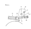
- the further embodiment of the braking device on a motor chain saw 10 shown in FIG. 1 is designated by 200.
- an indicated saw chain 11 is driven around a sword 12 via a drive (not shown).
- a brake drum 13 is connected to the drive via a centrifugal clutch, also not shown, to which a gear wheel, also not shown, for driving the saw chain 11 is connected.
- a front handle 15 is arranged, which is gripped together with a rear handle, also not shown, during operation of the motor chain saw.
- a hand protection lever 16 is arranged in the area of the handle 15 and can be pivoted about an axis 17 which is fixed to the housing and is formed by an axle bolt 17a. The hand protection lever 16 is used to trigger the braking device 200 in the event of a threatening operating state.
- the brake band 18 wrapped around the brake drum 13 is fastened at one end 18a to a fastening pin 19 fixed to the housing, while the other end 18b is fastened to a guide member 50 which is linearly guided and displaceable in a guide 51 is.
- the guide member 50 is arranged on a sliding block 53 which is displaceably mounted in a cylindrical sleeve 52 and is provided with a bolt 54.
- the bolt 54 extends through a spiral spring 55 which is supported on the one hand on the sliding block 53 and on the other hand at the end 56 of the sleeve 52.
- the brake spring 55 is designed as a compression spring so that a displacement of the guide member 50 into the sleeve 52, which corresponds to a solution of the brake band 18, takes place against the spring force of the brake spring 55.
- the guide member 50 is held in a position (rest position) via a mechanism which will be explained below, in which the brake spring 55 is pre-tensioned, so that when the guide member 50 is released under the action of the brake spring 55, the brake band 18 is tensioned and thus a braking process takes place .
- An intermediate member 57 is arranged on the guide member 50 to form a pivot axis 58, which is connected via a further pivot axis 59 to a one-armed pivot lever 60 which can be pivoted about a pivot axis 61 fixed to the housing.
- the arrangement is such that a knee joint is formed by the intermediate member 57 and the pivoting lever 60 that can be pivoted into a locking and a release position.
- the area of the pivot axis 58, about which the intermediate member 57 can be pivoted on the pivot lever 60, is designed as an actuating cam 64 and can be placed against a triggering and latching section 62 of the hand protection lever 16.
- the triggering and latching section 62 of the hand protection lever 16 is designed as a control curve 63 with a corresponding indentation 65, wherein within the indentation 65 the point 66 of the strongest retraction forms the locking point of the toggle joint and the point of rest of the hand protection lever 16 in the release position.
- the control cam 39 is provided with an approximately arc-shaped indentation 65, wherein, in addition to the point of greatest retraction, the actuating cam rest point is provided with two contact sections 65a, 65b which are designed in such a way that when the actuating cam 64 contacts the area 65a of the control cam 39 and from Guide handle leading away a pivoting of the hand protection lever, a pivoting of the pivoting lever 60 about the pivot axis 61 takes place such that the toggle joint is unlocked from its locked and tensioned position and pivoting of the pivoting lever 60 and the intermediate member 57 takes place such that the braking device 200 from the 6 position brought into the position shown in Fig. 7 and triggered.
- a tensioning lever 69 Arranged on the hand protection lever 16 is a tensioning lever 69 which can be pivoted about a pivot axis 71 and is arranged at a distance 72 from the pivot axis 17 of the hand protection lever and in the free end 70 of which an elongated hole 68 is formed in the longitudinal direction of the tension lever.
- a bolt 67 is provided which engages in the elongated hole 68, the elongated hole arrangement being such that a movement of the hand protection lever 16 about the pivot axis 17 is possible in the scope of the play given by the elongated hole 68 with respect to the bolt 67 .
- the control curve 63 moves along the actuating cam 64, and it is possible to pivot the toggle joint into its latching position.
- This pivoting takes place in that the clamping lever 69 pivoted with the hand protection lever 16 takes the pin 67 with it during the pivoting movement and thus pivots the pivot lever 60 clockwise into the latching position.
- the actuating cam 64 after contacting the section 65b of the control cam 63, finally takes the position in FIG Fig. 6 shown position in point 66.
- the braking device is now again in the biased and locked rest position of the system.
- the pivoting lever 60 When the brake is triggered by moving the hand protection lever 16 clockwise, the pivoting lever 60 can be pivoted freely after actuation, since the elongated hole 68 enables the pivoting lever 60 to pivot independently of the pivoting movement of the hand protection lever 16.
- the control cam 63 is arranged such that the actuating cam rest point 66 is arranged on the pressure action line 73, which runs between the center of the pivot axis 59 and the center of the axis 17 of the hand protection lever 16, and that the sections 65a, 65b are at an angle to a perpendicular S which are perpendicular to the pressure action line 73, are arranged (Fig.2).
- toggle lever mechanism is also within the scope of the invention, as is another embodiment of the tensioning mechanism, provided that the holding force for the hand protection lever is generated by the brake spring, so that the two arrangements described above are only to be regarded as exemplary embodiments.
Landscapes
- Engineering & Computer Science (AREA)
- General Engineering & Computer Science (AREA)
- Mechanical Engineering (AREA)
- Life Sciences & Earth Sciences (AREA)
- Wood Science & Technology (AREA)
- Forests & Forestry (AREA)
- Braking Arrangements (AREA)
Priority Applications (2)
| Application Number | Priority Date | Filing Date | Title |
|---|---|---|---|
| DE59006368T DE59006368D1 (de) | 1990-01-30 | 1990-01-30 | Bremseinrichtung an einer motorgetriebenen Handsäge, insbesondere einer Motorkettensäge. |
| AT90101774T ATE108124T1 (de) | 1990-01-30 | 1990-01-30 | Bremseinrichtung an einer motorgetriebenen handsäge, insbesondere einer motorkettensäge. |
Applications Claiming Priority (1)
| Application Number | Priority Date | Filing Date | Title |
|---|---|---|---|
| DE9001061U DE9001061U1 (de) | 1990-01-31 | 1990-01-31 | Bremseinrichtung an einer motorgetriebenen Handsäge, insbesondere einer Motorkettensäge |
Publications (3)
| Publication Number | Publication Date |
|---|---|
| EP0440827A2 true EP0440827A2 (fr) | 1991-08-14 |
| EP0440827A3 EP0440827A3 (en) | 1991-11-06 |
| EP0440827B1 EP0440827B1 (fr) | 1994-07-06 |
Family
ID=6850525
Family Applications (1)
| Application Number | Title | Priority Date | Filing Date |
|---|---|---|---|
| EP19900101774 Expired - Lifetime EP0440827B1 (fr) | 1990-01-30 | 1990-01-30 | Dispositif de freinage pour une scie à main motorisée, en particulier une scie à chaîne |
Country Status (2)
| Country | Link |
|---|---|
| EP (1) | EP0440827B1 (fr) |
| DE (1) | DE9001061U1 (fr) |
Families Citing this family (3)
| Publication number | Priority date | Publication date | Assignee | Title |
|---|---|---|---|---|
| US10029386B2 (en) * | 2009-08-26 | 2018-07-24 | Robert Bosch Tool Corporation | Table saw with positive locking mechanism |
| CN107191515B (zh) * | 2017-05-19 | 2023-03-21 | 中建八局第二建设有限公司 | 一种离心式悬吊钩超速控制装置 |
| US12064894B2 (en) | 2020-09-04 | 2024-08-20 | Milwaukee Electric Tool Corporation | Chainsaw |
Family Cites Families (6)
| Publication number | Priority date | Publication date | Assignee | Title |
|---|---|---|---|---|
| FR1561375A (fr) * | 1968-02-02 | 1969-03-28 | ||
| SE390131B (sv) * | 1971-04-13 | 1976-12-06 | Partner Ab | Bromsanordning vid motorsagar |
| US4011763A (en) * | 1975-06-13 | 1977-03-15 | General Electric Company | Shaft turning mechanism |
| US4197640A (en) * | 1978-09-18 | 1980-04-15 | Beaird-Poulan Division, Emerson Electric Co. | Safety braking apparatus for portable chain saw |
| SE8202949L (sv) * | 1982-05-11 | 1983-11-12 | Electrolux Motor Ab | Bromsutlosningsmekanism |
| US4651583A (en) * | 1985-04-16 | 1987-03-24 | Nippon Cable System, Inc. | Locking mechanism |
-
1990
- 1990-01-30 EP EP19900101774 patent/EP0440827B1/fr not_active Expired - Lifetime
- 1990-01-31 DE DE9001061U patent/DE9001061U1/de not_active Expired - Lifetime
Also Published As
| Publication number | Publication date |
|---|---|
| DE9001061U1 (de) | 1990-04-05 |
| EP0440827B1 (fr) | 1994-07-06 |
| EP0440827A3 (en) | 1991-11-06 |
Similar Documents
| Publication | Publication Date | Title |
|---|---|---|
| DE69502398T2 (de) | Einstell- und energieaufnahmemechanismus für eine kraftfahrzeuglenksäule | |
| DE69716149T2 (de) | Sägeblattaufspannvorrichtung | |
| EP0650805A1 (fr) | Outil électrique | |
| DE4021277A1 (de) | Handgefuehrtes arbeitsgeraet | |
| DE3929441C2 (de) | Handgeführtes Arbeitsgerät | |
| DE3905698C1 (en) | Device for locking the gear shift lever of a motor vehicle | |
| DE2503272A1 (de) | Tuerschlossfalle | |
| DE3528404C2 (fr) | ||
| WO1997026162A1 (fr) | Frein de stationnement pour vehicules a moteur, remorques de vehicules ou similaires | |
| DE2708290A1 (de) | Schneidzange fuer klemmschellen | |
| EP0320739A1 (fr) | Dispositif de réglage d'un ancrage de renvoi de sangle pour une ceinture de sécurité | |
| DE9404236U1 (de) | Einrichtung für einen Lastträger für ein Kraftfahrzeug mit Anhängerkupplung | |
| DE602004001198T2 (de) | Elektrische Verriegelung einer einstellbaren Lenksäule für ein Kraftfahrzeug | |
| EP0504557A1 (fr) | Dispositif de tension et d'amarrage pour sangles d'amarrage | |
| EP3542963B1 (fr) | Tenseur | |
| EP3107774A1 (fr) | Dispositif d'actionnement pour un frein de stationnement | |
| EP0440827B1 (fr) | Dispositif de freinage pour une scie à main motorisée, en particulier une scie à chaîne | |
| DE3037799C2 (fr) | ||
| DE19811094A1 (de) | Längsverstellvorrichtung für einen Sitz, insbesondere Kraftfahrzeugsitz | |
| DE2909777A1 (de) | Motorkettensaege | |
| DE4433595A1 (de) | Lenkstockschalter als Getriebeschalter mit fixierbarer Neutralstellung | |
| DE9100328U1 (de) | Bremseinrichtung an einer motorgetriebenen Handsäge, insbesondere einer Motorkettensäge | |
| DE4416864C1 (de) | Vorrichtung mit einem Wählhebel für Kraftfahrzeug-Automatikgetriebe | |
| DE2535677A1 (de) | Schwenkbarer scheinwerfer fuer fahrzeuge, insbesondere kraftfahrzeuge | |
| DE4129915A1 (de) | Sicherheitsanordnung fuer die bedienungselemente einer handgefuehrten, zur verdichtung des untergrundes vorgesehenen kraftbetriebenen walze |
Legal Events
| Date | Code | Title | Description |
|---|---|---|---|
| PUAI | Public reference made under article 153(3) epc to a published international application that has entered the european phase |
Free format text: ORIGINAL CODE: 0009012 |
|
| AK | Designated contracting states |
Kind code of ref document: A2 Designated state(s): AT BE CH DE DK ES FR GB GR IT LI LU NL SE |
|
| PUAL | Search report despatched |
Free format text: ORIGINAL CODE: 0009013 |
|
| AK | Designated contracting states |
Kind code of ref document: A3 Designated state(s): AT BE CH DE DK ES FR GB GR IT LI LU NL SE |
|
| 17P | Request for examination filed |
Effective date: 19911012 |
|
| RAP1 | Party data changed (applicant data changed or rights of an application transferred) |
Owner name: DOLMAR GMBH |
|
| 17Q | First examination report despatched |
Effective date: 19930609 |
|
| ITF | It: translation for a ep patent filed | ||
| GRAA | (expected) grant |
Free format text: ORIGINAL CODE: 0009210 |
|
| AK | Designated contracting states |
Kind code of ref document: B1 Designated state(s): AT BE CH DE DK ES FR GB GR IT LI LU NL SE |
|
| PG25 | Lapsed in a contracting state [announced via postgrant information from national office to epo] |
Ref country code: NL Effective date: 19940706 Ref country code: GR Free format text: LAPSE BECAUSE OF FAILURE TO SUBMIT A TRANSLATION OF THE DESCRIPTION OR TO PAY THE FEE WITHIN THE PRESCRIBED TIME-LIMIT Effective date: 19940706 Ref country code: GB Effective date: 19940706 Ref country code: FR Effective date: 19940706 Ref country code: ES Free format text: THE PATENT HAS BEEN ANNULLED BY A DECISION OF A NATIONAL AUTHORITY Effective date: 19940706 Ref country code: DK Effective date: 19940706 Ref country code: BE Effective date: 19940706 |
|
| REF | Corresponds to: |
Ref document number: 108124 Country of ref document: AT Date of ref document: 19940715 Kind code of ref document: T |
|
| REF | Corresponds to: |
Ref document number: 59006368 Country of ref document: DE Date of ref document: 19940811 |
|
| EN | Fr: translation not filed | ||
| NLV1 | Nl: lapsed or annulled due to failure to fulfill the requirements of art. 29p and 29m of the patents act | ||
| GBV | Gb: ep patent (uk) treated as always having been void in accordance with gb section 77(7)/1977 [no translation filed] |
Effective date: 19940706 |
|
| PG25 | Lapsed in a contracting state [announced via postgrant information from national office to epo] |
Ref country code: AT Effective date: 19950130 |
|
| EAL | Se: european patent in force in sweden |
Ref document number: 90101774.9 |
|
| PG25 | Lapsed in a contracting state [announced via postgrant information from national office to epo] |
Ref country code: LU Free format text: LAPSE BECAUSE OF NON-PAYMENT OF DUE FEES Effective date: 19950131 Ref country code: LI Effective date: 19950131 Ref country code: CH Effective date: 19950131 |
|
| PLBE | No opposition filed within time limit |
Free format text: ORIGINAL CODE: 0009261 |
|
| STAA | Information on the status of an ep patent application or granted ep patent |
Free format text: STATUS: NO OPPOSITION FILED WITHIN TIME LIMIT |
|
| 26N | No opposition filed | ||
| REG | Reference to a national code |
Ref country code: CH Ref legal event code: PL |
|
| PGFP | Annual fee paid to national office [announced via postgrant information from national office to epo] |
Ref country code: SE Payment date: 20010130 Year of fee payment: 12 |
|
| PGFP | Annual fee paid to national office [announced via postgrant information from national office to epo] |
Ref country code: DE Payment date: 20010320 Year of fee payment: 12 |
|
| PG25 | Lapsed in a contracting state [announced via postgrant information from national office to epo] |
Ref country code: SE Free format text: LAPSE BECAUSE OF NON-PAYMENT OF DUE FEES Effective date: 20020131 |
|
| PG25 | Lapsed in a contracting state [announced via postgrant information from national office to epo] |
Ref country code: DE Free format text: LAPSE BECAUSE OF NON-PAYMENT OF DUE FEES Effective date: 20020801 |
|
| EUG | Se: european patent has lapsed |
Ref document number: 90101774.9 |
|
| PG25 | Lapsed in a contracting state [announced via postgrant information from national office to epo] |
Ref country code: IT Free format text: LAPSE BECAUSE OF NON-PAYMENT OF DUE FEES;WARNING: LAPSES OF ITALIAN PATENTS WITH EFFECTIVE DATE BEFORE 2007 MAY HAVE OCCURRED AT ANY TIME BEFORE 2007. THE CORRECT EFFECTIVE DATE MAY BE DIFFERENT FROM THE ONE RECORDED. Effective date: 20050130 |