EP0440855A1 - Ensemble de valve À vaporiser - Google Patents
Ensemble de valve À vaporiser Download PDFInfo
- Publication number
- EP0440855A1 EP0440855A1 EP90102467A EP90102467A EP0440855A1 EP 0440855 A1 EP0440855 A1 EP 0440855A1 EP 90102467 A EP90102467 A EP 90102467A EP 90102467 A EP90102467 A EP 90102467A EP 0440855 A1 EP0440855 A1 EP 0440855A1
- Authority
- EP
- European Patent Office
- Prior art keywords
- valve
- main
- channel
- section
- main channel
- Prior art date
- Legal status (The legal status is an assumption and is not a legal conclusion. Google has not performed a legal analysis and makes no representation as to the accuracy of the status listed.)
- Withdrawn
Links
- 239000007921 spray Substances 0.000 title claims abstract description 18
- 239000000443 aerosol Substances 0.000 claims abstract description 21
- 238000011144 upstream manufacturing Methods 0.000 claims abstract description 6
- 230000002093 peripheral effect Effects 0.000 claims description 5
- 239000000463 material Substances 0.000 claims description 3
- 239000007788 liquid Substances 0.000 description 19
- 239000003380 propellant Substances 0.000 description 17
- 238000000889 atomisation Methods 0.000 description 4
- 210000002445 nipple Anatomy 0.000 description 4
- 239000000203 mixture Substances 0.000 description 2
- 229910000831 Steel Inorganic materials 0.000 description 1
- 238000010276 construction Methods 0.000 description 1
- 238000011161 development Methods 0.000 description 1
- 230000018109 developmental process Effects 0.000 description 1
- 239000000945 filler Substances 0.000 description 1
- 239000002184 metal Substances 0.000 description 1
- 238000005507 spraying Methods 0.000 description 1
- 239000010959 steel Substances 0.000 description 1
Images

Classifications
-
- B—PERFORMING OPERATIONS; TRANSPORTING
- B65—CONVEYING; PACKING; STORING; HANDLING THIN OR FILAMENTARY MATERIAL
- B65D—CONTAINERS FOR STORAGE OR TRANSPORT OF ARTICLES OR MATERIALS, e.g. BAGS, BARRELS, BOTTLES, BOXES, CANS, CARTONS, CRATES, DRUMS, JARS, TANKS, HOPPERS, FORWARDING CONTAINERS; ACCESSORIES, CLOSURES, OR FITTINGS THEREFOR; PACKAGING ELEMENTS; PACKAGES
- B65D83/00—Containers or packages with special means for dispensing contents
- B65D83/14—Containers for dispensing liquid or semi-liquid contents by internal gaseous pressure, i.e. aerosol containers comprising propellant
- B65D83/36—Containers for dispensing liquid or semi-liquid contents by internal gaseous pressure, i.e. aerosol containers comprising propellant allowing operation in any orientation
-
- B—PERFORMING OPERATIONS; TRANSPORTING
- B65—CONVEYING; PACKING; STORING; HANDLING THIN OR FILAMENTARY MATERIAL
- B65D—CONTAINERS FOR STORAGE OR TRANSPORT OF ARTICLES OR MATERIALS, e.g. BAGS, BARRELS, BOTTLES, BOXES, CANS, CARTONS, CRATES, DRUMS, JARS, TANKS, HOPPERS, FORWARDING CONTAINERS; ACCESSORIES, CLOSURES, OR FITTINGS THEREFOR; PACKAGING ELEMENTS; PACKAGES
- B65D83/00—Containers or packages with special means for dispensing contents
- B65D83/14—Containers for dispensing liquid or semi-liquid contents by internal gaseous pressure, i.e. aerosol containers comprising propellant
Definitions
- the invention relates to a spray valve arrangement for an aerosol can, with a valve housing that can be inserted with an upper end section in the can top, limits a main channel for the passage of the can contents, in the main channel a main valve with a manually operable against the force of a spring hollow Valve stem and a rubber-elastic washer, which cooperates as a valve closure piece with at least one lateral valve opening in the valve stem, and has a secondary channel connecting the can space with the main channel in front of the main valve, and with a dip tube extending the main channel for the passage of the can contents.
- a secondary valve with a closure piece in the form of a ball is formed in the secondary channel, which blocks the escape of propellant gas via the secondary channel and upside down when the aerosol can is kept upright -Location of the can opens the secondary valve, so that the valve can be largely emptied even in this position.
- the outlet nozzle must have a sufficient opening cross section. However, this counteracts a fine atomization of the product contained in the can in the form of a liquid. In addition, the relatively large opening cross section of the outlet nozzle leads to a correspondingly high dispensing speed, which runs counter to economical consumption of the product.
- the invention is based on the object of specifying a spray valve arrangement of the generic type which enables at least economical consumption of the can contents.
- a solution to this problem is that the main channel between the main valve and the junction of the main and secondary channel has a first throttle section, that in a branch channel leading from the secondary channel to the main channel between the first throttle section and the main valve there is a second throttle section and that Throttle cross sections of the two throttle sections are approximately the same and smaller than 0.2 mm2.
- the throttle sections ensure a relatively slow product discharge rate of less than 0.8 g / sec.
- sufficient atomization is made possible despite the low dispensing speed, because product and propellant gas are mixed in front of the main valve in the dispensing channel, which facilitates atomization.
- the aerosol can is held upside down, i.e. with the outlet opening facing down, there is no mixing of product and propellant gas as long as the fill level has not dropped below the mouth of the secondary duct into the main duct, but there is still a substantial amount Emptying the can too possible in the upside-down position, with the product and propellant gas being mixed again in the last phase of emptying.
- the housing can have a mixing chamber with a bottom wall and a top wall, which extend transversely to a longitudinal axis of the housing, of which the bottom wall from the first throttle section and the top wall from a central outlet opening is penetrated, and that the second throttle section opens into an annular channel surrounding the mixing chamber, which is connected to the mixing chamber by radial transverse channels.
- the product and the propellant gas meet at predetermined angles in the mixing chamber, which promote the intensive mixing.
- the secondary duct has a secondary valve between the branching point of the branch duct and the main duct, which acts as a closure piece has the ball occupying the closed position under its own weight.
- the generic spray valve arrangement can also be designed in such a way that only the main duct has a throttle section, the throttle cross-section of which is smaller than 0.2 mm2, and that the secondary duct has a secondary valve which, as a closure piece, has a ball which assumes the closed position under its own weight . This also ensures a low exit velocity of the product from the aerosol can, but without mixing with the propellant gas, the escape of which is prevented by the secondary valve when the aerosol can is kept upright.
- Yet another embodiment of the generic spray valve arrangement can consist in that the main and secondary channels each have a throttle section upstream of the main valve, the throttle cross sections of which are approximately the same and smaller than 0.2 mm2.
- This training does not require a secondary valve. It is therefore correspondingly simple.
- a low exit speed and intensive mixing of product and propellant gas are ensured.
- valve stem is passed through an opening in the upper part of the can, the diameter of which is larger than that of the valve stem, and that the housing has radially projecting vertical ribs on its outside between its upper end section and the upper part of the can, on the upper end face thereof a radially outer circumferential portion of the washer rests and in the spaces between the material of the circumferential portion of the washer can dodge under the filling pressure when filling the can, so that a filling channel with a large flow cross section is released.
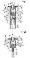
- FIGS. 1 and 2 is in an only partially shown upper part 1 of an aerosol can an open main valve with a partially shown in section, the actuation of the valve and the output serving hollow valve stem 2, a closure piece 3 in the form of a rubber-elastic Washer and a valve housing 4 made of plastic.
- the valve housing 4 has an upper end section 5 and a lower end section 6.
- the upper end section 5 is tightly crimped in the upper part 1 of the can.
- the lower end section 6 has a connection nipple 7 for a dip tube 8, which is only partially shown, and which projects into the vicinity of the (not shown) can bottom into the can contents and is open at the bottom.
- valve stem 2 is guided with its lower, thicker end, which has vertical ribs on the outside, in the upper end section 5 and is seated with its upper end in a main valve actuating head 9, which has a spray opening.
- the lower end of the valve stem 2 is supported by a spring 10 for resetting the valve stem 2 in a cup-shaped housing insert 11.
- the bottom of the housing insert 11 forms a top wall 12a of a mixing chamber 12 which extends transversely to a vertical longitudinal axis of the housing 4 and has a bottom wall 12b.
- the bottom wall 12b together with the lower end section 6 of the housing 4, delimits a secondary valve chamber 13 of a secondary valve acting as a changeover valve, which has a valve ball 14 made of metal, preferably steel, and a frustoconical valve seat 15 below the ball 14 in the lower end section 6 of the housing 4.
- a secondary duct 17 which begins in the upright posture of the valve arrangement above the maximum fill level of the can, connects the area of the interior of the can filled with compressed gas via a secondary valve 14, 15 to a main duct 21, the mouth 18 of the secondary duct 17 lies at the lowest point of the valve seat 15 below the ball 14.
- the secondary channel 17 is designed as a transverse or horizontal opening 19 which merges into the vertically extending, cylindrical secondary valve chamber 13.
- the diameter of the ball 14 is smaller than the inner diameter of the secondary valve chamber 13.
- the course of the main channel 21 for the passage of the can contents is shown as a dashed line. It extends through the dip tube 8, the nipple 7, an opening 22 between the outer wall of the lower housing end section 6 and the inner housing wall 23 of the secondary valve chamber 13, an axial channel 24 between rule the outer wall of the housing end portion 6 and the housing wall 23, a throttle portion 25 in the form of a bore with a cross section of less than 0.2 mm2, which extends through the bottom wall 12b, the mixing chamber 12, a central axial outlet opening 26 in the Cover wall 12a of the mixing chamber 12, a main valve housing space 27, at least one radial valve opening 28 in the valve stem 2, an axial bore 29 in the valve stem 2 and the outlet nozzle opening in the actuating head 9.
- connection point between the main and secondary duct lies in front of the throttle section 25 in the nipple 7 and therefore the throttle section 25 between this connection point and the main valve 2, 3.
- a second throttle section 30 with a throttle cross section of less than 0.2 mm 2, which opens into an annular duct 31 surrounding the mixing chamber 12.
- the annular channel 31 is connected to the mixing chamber 12 by radial transverse channels 32.
- the ball 14 In the normal vertical or upright position of the aerosol can or the valve arrangement shown, the ball 14, due to its weight, blocks the secondary duct 17 against the pressure of the propellant gas, which fills the can space above the liquid or fill level located below the opening 19.
- the propellant gas can therefore only escape in the illustrated open position of the main valve 2, 3 via the branch duct 29, the throttle section 30, the annular duct 31, the radial transverse ducts 32 and the mixing chamber 12.
- the throttle cross section of the throttle section 30 is very small with less than 0.2 m2 and preferably still somewhat smaller than the throttle cross section of the throttle section 25, not only the propellant gas escapes, but also the liquid contained in the can space via the main channel 21, which is Mix the propellant gas and the liquid in the mixing chamber 12 intensively before the mixture continues to exit via the main channel, spraying it at the outlet can opening.
- the small throttle cross-sections of the throttle sections 25 and 30 ensure that the outlet speed of the can contents is relatively low, so that it can only be used sparingly. Nevertheless, an intensive mixing of propellant gas and liquid and consequently a fine atomization of the liquid at the outlet nozzle opening is ensured.
- the valve ball 14 releases the secondary duct 17, while the branch duct 29 is still not blocked by the valve ball 14.
- the liquid can therefore escape not only via the branch duct 29 but also via the secondary duct 17 and the main duct 21.
- the opening 19 which is relatively far down in the position according to FIG. 2, enables the aerosol can to be emptied further than without the branch duct 29.
- FIGS. 3 and 4 differs from that of FIGS. 1 and 2 essentially only in that the mixing chamber 12 is omitted. Instead, the throttle sections 25 and 30 extend through the bottom wall of the housing insert 11. The propellant gas and liquid are therefore only mixed in the main valve chamber 27 between the throttle sections 25 and 30 on the one hand and the valve opening 28 on the other hand.
- the construction of this valve arrangement is therefore somewhat simpler than that according to FIGS. 1 and 2. Otherwise, the mode of operation of the two exemplary embodiments is the same.
- the can is filled in the exemplary embodiments according to FIGS. 1 to 4 with the actuating head 9 removed through a gap between the valve stem 2 and an opening 34 penetrated by it in the upper part 1 of the can and partly through the opening of the annular disc 3, the main valve chamber 27 and Throttle sections 25, 30.
- the housing 4 is therefore provided on its outer side between its upper end section 5 and the can upper part 1 with radially projecting vertical ribs 35, on the upper side of which the radially outer peripheral section of the ring disk 3 rests and in the spaces between the material of the peripheral section of the ring disc 3 can dodge under the filling pressure when filling the can. In this way, an additional filler channel with a large flow cross-section is released between the upper wall of the upper part 1 of the can and the upper side of the ring disk 3 and via the spaces between the ribs 35, which enables rapid filling.
- FIG. 6 differs from that of FIG. 5 essentially only in that the housing insert 11 and the auxiliary valve 14, 15 with its housing 23 are omitted and instead the axial bore of the nipple 7 as a throttle section 25 and that of the others Embodiments of relatively wide housing opening 19 has been narrowed to a second throttle section 30, the secondary duct 17 running over this throttle section 30 and main duct 21 and secondary duct 17 unite behind the throttle sections 25 and 30 in the main valve chamber 27 in front of the valve opening 28.
- the housing 4 is still ver with radially and axially extending ribs 37 see between which the liquid, after it has flowed through the throttle section 25, can emerge freely and which, like the housing insert 11 in the previous exemplary embodiments, support the spring 10 radially.
Landscapes
- Chemical & Material Sciences (AREA)
- Dispersion Chemistry (AREA)
- Engineering & Computer Science (AREA)
- Mechanical Engineering (AREA)
- Containers And Packaging Bodies Having A Special Means To Remove Contents (AREA)
Priority Applications (1)
| Application Number | Priority Date | Filing Date | Title |
|---|---|---|---|
| EP90102467A EP0440855A1 (fr) | 1990-02-08 | 1990-02-08 | Ensemble de valve À vaporiser |
Applications Claiming Priority (1)
| Application Number | Priority Date | Filing Date | Title |
|---|---|---|---|
| EP90102467A EP0440855A1 (fr) | 1990-02-08 | 1990-02-08 | Ensemble de valve À vaporiser |
Publications (1)
| Publication Number | Publication Date |
|---|---|
| EP0440855A1 true EP0440855A1 (fr) | 1991-08-14 |
Family
ID=8203611
Family Applications (1)
| Application Number | Title | Priority Date | Filing Date |
|---|---|---|---|
| EP90102467A Withdrawn EP0440855A1 (fr) | 1990-02-08 | 1990-02-08 | Ensemble de valve À vaporiser |
Country Status (1)
| Country | Link |
|---|---|
| EP (1) | EP0440855A1 (fr) |
Cited By (5)
| Publication number | Priority date | Publication date | Assignee | Title |
|---|---|---|---|---|
| WO1994000367A1 (fr) * | 1992-06-22 | 1994-01-06 | Joseph Ferraye | Systeme universel de propulsion progressive et ou d'atomisation active pour aerosols |
| US5350088A (en) * | 1993-09-13 | 1994-09-27 | Summit Packaging Systems, Inc. | Invertible aerosol valve |
| US5803319A (en) * | 1996-01-19 | 1998-09-08 | Summit Packaging Systems, Inc. | Invertible spray valve and container containing same |
| EP1149776A3 (fr) * | 2000-03-03 | 2004-01-02 | de Schrijver, Aster | Valve |
| CN117022919A (zh) * | 2023-07-14 | 2023-11-10 | 广州侍美科技有限公司 | 一种双管路取液装置、取液系统和取液方法 |
Citations (6)
| Publication number | Priority date | Publication date | Assignee | Title |
|---|---|---|---|---|
| DE1906681A1 (de) * | 1968-02-09 | 1969-09-18 | Rexall Drug Chemical | Ventil fuer die Abgabe stroemungsfaehiger Medien |
| US4019657A (en) * | 1975-03-03 | 1977-04-26 | Spitzer Joseph G | Aerosol containers for foaming and delivering aerosols |
| EP0008109A1 (fr) * | 1978-08-08 | 1980-02-20 | Joseph George Spitzer | Récipient pour aérosol et système de valve destinés à des fluides propulseurs liquéfiés inflammables et procédé pour émettre un brouillard d'une très faible inflammabilité |
| US4247025A (en) * | 1979-08-06 | 1981-01-27 | Summit Packaging Systems, Inc. | Aerosol valve having liquid-phase/vapor-phase mixer-homogenizer |
| GB2058229A (en) * | 1979-08-28 | 1981-04-08 | Perfect Ventil Gmbh | An aerosol can |
| EP0043514A1 (fr) * | 1980-07-08 | 1982-01-13 | Deutsche Präzisions-Ventil GmbH | Ensemble de valve à vaporiser |
-
1990
- 1990-02-08 EP EP90102467A patent/EP0440855A1/fr not_active Withdrawn
Patent Citations (6)
| Publication number | Priority date | Publication date | Assignee | Title |
|---|---|---|---|---|
| DE1906681A1 (de) * | 1968-02-09 | 1969-09-18 | Rexall Drug Chemical | Ventil fuer die Abgabe stroemungsfaehiger Medien |
| US4019657A (en) * | 1975-03-03 | 1977-04-26 | Spitzer Joseph G | Aerosol containers for foaming and delivering aerosols |
| EP0008109A1 (fr) * | 1978-08-08 | 1980-02-20 | Joseph George Spitzer | Récipient pour aérosol et système de valve destinés à des fluides propulseurs liquéfiés inflammables et procédé pour émettre un brouillard d'une très faible inflammabilité |
| US4247025A (en) * | 1979-08-06 | 1981-01-27 | Summit Packaging Systems, Inc. | Aerosol valve having liquid-phase/vapor-phase mixer-homogenizer |
| GB2058229A (en) * | 1979-08-28 | 1981-04-08 | Perfect Ventil Gmbh | An aerosol can |
| EP0043514A1 (fr) * | 1980-07-08 | 1982-01-13 | Deutsche Präzisions-Ventil GmbH | Ensemble de valve à vaporiser |
Cited By (7)
| Publication number | Priority date | Publication date | Assignee | Title |
|---|---|---|---|---|
| WO1994000367A1 (fr) * | 1992-06-22 | 1994-01-06 | Joseph Ferraye | Systeme universel de propulsion progressive et ou d'atomisation active pour aerosols |
| US5350088A (en) * | 1993-09-13 | 1994-09-27 | Summit Packaging Systems, Inc. | Invertible aerosol valve |
| GB2282418A (en) * | 1993-09-13 | 1995-04-05 | Summit Packaging Syst | Invertible aerosol valve |
| GB2282418B (en) * | 1993-09-13 | 1995-10-25 | Summit Packaging Syst | Invertible aerosol valve |
| US5803319A (en) * | 1996-01-19 | 1998-09-08 | Summit Packaging Systems, Inc. | Invertible spray valve and container containing same |
| EP1149776A3 (fr) * | 2000-03-03 | 2004-01-02 | de Schrijver, Aster | Valve |
| CN117022919A (zh) * | 2023-07-14 | 2023-11-10 | 广州侍美科技有限公司 | 一种双管路取液装置、取液系统和取液方法 |
Similar Documents
| Publication | Publication Date | Title |
|---|---|---|
| DE69201796T2 (de) | Aerosol-druckbehälterventil und druckbehälter versehen mit einem solchen ventil. | |
| DE69305577T2 (de) | Druckgasvorrichtung zum einmaligen Versprühen einer begrenzten Menge eines flüssigen Materials in fein verteilten Teilchen | |
| DE19837127A1 (de) | Spender für Medien | |
| DE2749219A1 (de) | Dosierventil | |
| EP0000688A2 (fr) | Tête de pulvérisation | |
| EP0057226A1 (fr) | Regulateur de poussee dispose a l'interieur d'un recipient pressurise. | |
| EP0043514B1 (fr) | Ensemble de valve à vaporiser | |
| DE69714025T2 (de) | Verteilungseinrichtung einer einmaligen dosis eines flüssigen produktes | |
| EP0053350B1 (fr) | Appareil pour vaporiser un liquide d'un récipient | |
| DE2215605A1 (de) | Austeiler ventil für Aerosolbehälter | |
| DE8715785U1 (de) | Ventil | |
| DE3834091C2 (fr) | ||
| EP0440855A1 (fr) | Ensemble de valve À vaporiser | |
| EP3023752A1 (fr) | Distributeur de liquide et tête distributrice correspondante | |
| DE2017878A1 (de) | Ventil zur Zerstäubung von flüssigen Erzeugnissen unter Druck | |
| DE602004010815T2 (de) | Fluidproduktabgabekopf und dessen verwendung | |
| DE9110905U1 (de) | Verschäumer-Sprühkopf | |
| DE9005488U1 (de) | Verschlußkappe | |
| DE69314814T2 (de) | Aerosolventil | |
| DE2540914C2 (de) | Augenwaschflasche | |
| DE9311617U1 (de) | Verschluß für Behälter mit flüssigem oder pastenförmigem Inhalt | |
| EP0245319B1 (fr) | Dispositif de distribution de matieres visqueuses telles que des liquides, cremes, pates ou similaires contenus dans un recipient de stockage | |
| DE2450841A1 (de) | Ventil fuer einen aerosolbehaelter | |
| DE2832650A1 (de) | Verschluss zur verwendung bei der abgabe eines sprays | |
| CH615399A5 (en) | Liquid dispenser |
Legal Events
| Date | Code | Title | Description |
|---|---|---|---|
| PUAI | Public reference made under article 153(3) epc to a published international application that has entered the european phase |
Free format text: ORIGINAL CODE: 0009012 |
|
| AK | Designated contracting states |
Kind code of ref document: A1 Designated state(s): DE ES FR GB IT |
|
| STAA | Information on the status of an ep patent application or granted ep patent |
Free format text: STATUS: THE APPLICATION IS DEEMED TO BE WITHDRAWN |
|
| 18D | Application deemed to be withdrawn |
Effective date: 19920215 |