EP0440894A2 - Circuit de déclenchement à réglage automatique de la valeur de référence - Google Patents
Circuit de déclenchement à réglage automatique de la valeur de référence Download PDFInfo
- Publication number
- EP0440894A2 EP0440894A2 EP19900122128 EP90122128A EP0440894A2 EP 0440894 A2 EP0440894 A2 EP 0440894A2 EP 19900122128 EP19900122128 EP 19900122128 EP 90122128 A EP90122128 A EP 90122128A EP 0440894 A2 EP0440894 A2 EP 0440894A2
- Authority
- EP
- European Patent Office
- Prior art keywords
- signal
- comparator
- trigger circuit
- circuit according
- reference value
- Prior art date
- Legal status (The legal status is an assumption and is not a legal conclusion. Google has not performed a legal analysis and makes no representation as to the accuracy of the status listed.)
- Granted
Links
Images
Classifications
-
- F—MECHANICAL ENGINEERING; LIGHTING; HEATING; WEAPONS; BLASTING
- F02—COMBUSTION ENGINES; HOT-GAS OR COMBUSTION-PRODUCT ENGINE PLANTS
- F02D—CONTROLLING COMBUSTION ENGINES
- F02D41/00—Electrical control of supply of combustible mixture or its constituents
- F02D41/009—Electrical control of supply of combustible mixture or its constituents using means for generating position or synchronisation signals
-
- F—MECHANICAL ENGINEERING; LIGHTING; HEATING; WEAPONS; BLASTING
- F02—COMBUSTION ENGINES; HOT-GAS OR COMBUSTION-PRODUCT ENGINE PLANTS
- F02P—IGNITION, OTHER THAN COMPRESSION IGNITION, FOR INTERNAL-COMBUSTION ENGINES; TESTING OF IGNITION TIMING IN COMPRESSION-IGNITION ENGINES
- F02P17/00—Testing of ignition installations, e.g. in combination with adjusting; Testing of ignition timing in compression-ignition engines
- F02P17/02—Checking or adjusting ignition timing
-
- G—PHYSICS
- G01—MEASURING; TESTING
- G01D—MEASURING NOT SPECIALLY ADAPTED FOR A SPECIFIC VARIABLE; ARRANGEMENTS FOR MEASURING TWO OR MORE VARIABLES NOT COVERED IN A SINGLE OTHER SUBCLASS; TARIFF METERING APPARATUS; MEASURING OR TESTING NOT OTHERWISE PROVIDED FOR
- G01D1/00—Measuring arrangements giving results other than momentary value of variable, of general application
- G01D1/18—Measuring arrangements giving results other than momentary value of variable, of general application with arrangements for signalling that a predetermined value of an unspecified parameter has been exceeded
-
- H—ELECTRICITY
- H03—ELECTRONIC CIRCUITRY
- H03K—PULSE TECHNIQUE
- H03K5/00—Manipulating of pulses not covered by one of the other main groups of this subclass
- H03K5/153—Arrangements in which a pulse is delivered at the instant when a predetermined characteristic of an input signal is present or at a fixed time interval after this instant
- H03K5/1534—Transition or edge detectors
-
- F—MECHANICAL ENGINEERING; LIGHTING; HEATING; WEAPONS; BLASTING
- F02—COMBUSTION ENGINES; HOT-GAS OR COMBUSTION-PRODUCT ENGINE PLANTS
- F02B—INTERNAL-COMBUSTION PISTON ENGINES; COMBUSTION ENGINES IN GENERAL
- F02B3/00—Engines characterised by air compression and subsequent fuel addition
- F02B3/06—Engines characterised by air compression and subsequent fuel addition with compression ignition
Definitions
- the invention relates to a trigger circuit which compares the amplitudes of the signal curve of a periodic signal with reference values dependent on the preceding signal curve of this signal and emits a trigger signal when the respective reference value is reached, and to a memory for the respective reference value.
- a trigger circuit is used for this purpose, which evaluates the electrical signal of a sensor that interacts with the respective injection valve. It takes place triggering, that is, evaluation of the amplitudes of the signal curve of the periodic signal originating from the transmitter. The triggering by comparison with a reference value is used as the time of the start of spraying. This is passed on to a computer of the control unit, which compares the determined start of injection with a predetermined map value of the control unit, regulation being carried out via an injection adjuster in such a way that the injection time always assumes the optimum value stored in the map.
- the size and shape of the signal fluctuate greatly depending on many engine parameters.
- the amplitude of the signal changes with the speed of the internal combustion engine. This also applies to the signal shape, in particular also for the signal edges. It was found that the start of spraying can be determined with sufficient certainty from the signal if triggering is always carried out when the signal amplitude of a considered period of the signal is approximately 20% of the maximum signal amplitude of the previous signal period. This therefore presupposes that a reference value of the previous signal period is available, which is approximately 20% of the associated maximum signal amplitude.
- the trigger signal is emitted and fed to the computer of the control unit, which carries out the comparison with the characteristic value and the regulation already mentioned.
- the disadvantage is that the signal from the encoder may be Post-impact pulses have amplitude peaks that are greater than the amplitude of the actual useful signal and have nothing to do with the start of spraying sought. This will falsify the result.
- the trigger circuit according to the invention with the features mentioned in the main claim has the advantage that occurring interference signals, in particular post-bounce pulses, are suppressed and are therefore not taken into account for the determination of the reference value.
- This makes it possible to determine the start of injection (SB) very precisely, so that optimal operation of the internal combustion engine is possible.
- the invention is not limited to use in automotive electronics, but can also be used in other fields.
- the interference pulses are masked out in accordance with the invention in that the reference value is determined only by a portion of a period of the signal. Therefore, only the portion of the respective period that contains the pure useful information is evaluated. The other part is disregarded.
- the first half-wave of each period of the signal is used to determine the reference value. This is preferably the positive half-wave of the signal.
- the post-impact pulses are in the area of the end of the spray.
- the memory is designed as a capacitor.
- the capacitor voltage then forms the reference value.
- a reference value is used which is proportional to the mentioned peak value of the first half-wave, that is to say it is 20% of the value, preferably by using a voltage divider maximum amplitude of this half wave.
- a first comparator which is used in the first, emits an output signal within a period of a change of sign of the signal which stops charging of the capacitor by the signal.
- the change in sign which follows the first positive half-wave and thus lies between this and the subsequent negative half-wave, is detected and used to stop the capacitor charging, so that subsequent signal components, in particular interference pulses / bounce pulses, are not taken into account.
- a fictitious zero line can be assumed here, which need not be at the potential "zero volt". For example, it is quite possible that this zero line is at 4.9 volts.
- a diode lies in series with the capacitor, the diode being controllable in its blocking state by the first comparator. If the aforementioned change of sign of the signal occurs, the first comparator switches and thereby blocks the diode, so that the charging of the capacitor is stopped.
- the first comparator has a monostable function, the switching back to its initial state only taking place when the signal has decayed in the respective period. This ensures that the interference pulses / post-bounce pulses that occur in each period of the signal are reliably masked out when the reference signal is determined.
- signals from the transmitter are initially set, which have a very large amplitude and then only give very small signals, for example due to overrun operation, then at least a partial discharge of the capacitor can be carried out by means of a discharge circuit after the respective triggering. This discharge takes place in a very short period of time and serves to allow the capacitor voltage (reference value) to adapt quickly to the new situation.
- a second comparator can be provided, which is used to compare the amplitudes of the signal with the reference values. This comparator thus determines the 20% value of the previous maximum amplitude in the considered portion of the associated period of the signal.
- the signal can originate from the sensor already mentioned, which is assigned to the injection valve of the internal combustion engine.
- the trigger signal marks the start of injection of the injection valve.
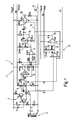
- FIG. 1 shows a circuit arrangement 1 which has a trigger circuit 2.
- the trigger circuit 2 is used to evaluate a signal S, which is supplied by an encoder 3.
- the encoder 3 is designed as an inductive needle movement sensor NBF. It interacts with an injection valve, not shown, of an internal combustion engine.
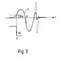
- the internal combustion engine is designed as a diesel engine. It has a fuel pump, which opens the injection valve on each pump stroke, as a result of which the needle movement sensor NBF responds and outputs the signal S (FIG. 2).
- a coil L of the needle movement sensor NBF is supplied by a regulated current source 4.
- the current source 4 is formed by the transistors T1 and T2 and the associated circuitry (resistors R1, R2 and R3, capacitor C1).
- An iron core cooperates with the coil L, which is moved when the injection valve is actuated and thereby causes an induction change in the coil L, which leads to the formation of the signal S which lies between a terminal A and ground 5.
- a diode D1 is connected in parallel with the coil L.
- Terminal A is connected via a capacitor C3 and a resistor R9 to the plus input of a comparator K1. Furthermore, a voltage divider consisting of the resistors R4, R5 and R7 is provided, a connection point 6 lying between the resistors R4 and R5 being connected via a resistor R8 to the plus input of the comparator K1 leads. The connection point 6 is also connected to ground 5 via a capacitor C2.
- the voltage divider mentioned is supplied by a stabilized voltage U stab . The stabilized voltage is 5 volts.
- a battery voltage U batt is provided, which among other things supplies the current source 4 with energy.
- the output 7 of the comparator K1 leads to a connection point 8 which is connected to the battery voltage U batt via a resistor R10. Furthermore, the anode of a diode D2 lies at the connection point 8, the cathode of which leads to a connection point 9. A capacitor C4 is connected between connection point 9 and ground 5. Furthermore, the minus input of the comparator K1 is connected to the connection point 9 via a line 10. A terminal C, which leads to connection point 9, is connected via a resistor R11 to the stabilized voltage U stab . It is also connected to the plus input of a further comparator K2. The minus input of the comparator K2 leads via a resistor R19 to a terminal B, which lies between the capacitor C3 and the resistor R9.
- the output 11 of the comparator K2 is connected to a series connection of resistors R12, R13, which lead to the stabilized voltage U stab .
- the output 11 of the comparator K2 is connected to the plus input of a comparator K3.
- This comparator K3 has an output 13, which leads via a capacitor C6 to the plus input of the comparator K3. Furthermore, the output 13 is connected to a terminal E, between which and the stabilized voltage U stab there is a resistor R14.
- An RC element is also provided, which is formed by a resistor R15 and a capacitor C7. The capacitor C7 is connected to the terminal E; the resistor R15 is connected to the stabilized voltage U stab .
- a connection point 14, which lies between the resistor R15 and the capacitor C7, is connected to the positive input of a further comparator K4.
- the minus input of the comparator K3 is connected via a line 15 to the minus input of the comparator K4.
- the output 16 of the comparator K4 is connected to the terminal C via a resistor R16.
- a blanking circuit 17 which has a comparator K5. Its negative input is connected to a terminal G, which leads to a connection point 18, which lies between the resistor R5 and the resistor R6 of the aforementioned voltage divider.
- the plus input of the comparator K5 leads to the terminal B.
- the output 19 of the comparator K5 leads to a voltage divider which is formed by resistors R17 and R18.
- the resistor R17 is connected to the stabilized voltage U stab .
- a connection point 20 between the resistors R17 and R18 is connected to the stabilized voltage U stab via a capacitor C8.
- the output 19 is connected via a line 21 to the positive input of a last comparator K6, the negative input of which leads to the negative input of the comparator K5.
- the output 22 of the comparator K6 is connected to a terminal D which leads to the connection point 8.
- the comparators K1, K2, K3, K4, K5 and K6 are supplied by the battery voltage U batt (only partially shown in FIG. 1).
- the circuit arrangement 1 works as follows: The signal S is transmitted via the capacitor C3 and via the resistor R19 to the minus input of the comparator K2.
- This comparator K2 represents a main evaluation comparator. It compares the signal S with a reference value REF at its positive input, which is at the terminal C and thus at the capacitor C4. If the signal S at the minus input of the comparator K2 exceeds the reference value REF, the comparator K3 also switches, as a result of which a negative edge F occurs at the point E, which characterizes the start of injection SB of the injection valve mentioned.
- the size of the reference value REF is proportional to the peak value of a first half-wave of the previous period of the signal S. This results for the following reasons: without the signal S, the terminal B has a slightly lower potential than the stabilized voltage U stab . The latter is 5 volts; preferably the low potential of point B can be 4.9 volts.
- the comparator K1 forms, together with the diode D2 and the resistor R10, a threshold-free rectifier circuit which charges the capacitor C4 to this 20% value. Since the resistor R11 has a very high resistance, the potential at C4 (reference value REF) between two periods of the signal S is virtually not reduced. This reference value REF is therefore used as a threshold by the comparator K2 for the subsequent period of the signal S. The maximum amplitude of the previous period of the signal S thus determines the reference value REF in the subsequent period of the signal S.
- the reference value REF for charging the capacitor C4, that is to say for the provision of the reference value REF, not the entire previous period of the signal S is evaluated, since otherwise it may be assumed that the amplitude peaks are too large, which originate from post-impact pulses and would therefore lead to a falsification when determining the start of spraying.
- only a portion of the corresponding period of the signal S is used to determine the reference value REF. This portion is selected such that it does not contain the post-rebound pulses mentioned.
- the first half-wave, in particular positive half-wave, of each period of the signal S is used to determine the reference value REF.
- the blanking circuit 17 fades out the region of the period that is provided with disturbances, in particular bounce pulses.
- the terminal B has a somewhat lower potential than the stabilized voltage U stab .
- terminal B is at 4.9 volts.
- the potential at terminal G is lower than at terminal B. For example, it is 4.5 volts.
- the potentials of terminals B and G are applied to the inputs of comparator K5.
- the potential at terminal G is fed to the minus input and forms a reference value.
- the comparator K5 is at its output 19 at "high" potential.
- ground potential is virtually applied to the connection point 8, as a result of which the diode D2 comes into its blocking state.
- the comparators K5 and K6 together with the capacitor C8 and the resistor R17, the comparators K5 and K6 form a monostable function which is selected such that the switching back to the initial state of the comparators K5 and K6 only takes place when the signal S has decayed again in the period in question is, that is, when the post-rebound pulses have disappeared.
- the change of sign of the Signal S at time t0 also has the physical meaning that the associated injector now assumes its open state. This information can be removed from terminal D and processed by the computer of the control unit. It should be borne in mind here that the time line in FIG. 2 does not necessarily have to correspond to a zero-volt potential line, rather it can also represent an average value line which has a positive potential, so that only fictitiously of "positive" and " negative "half-wave can be talked about.
- each spray pulse (terminal E) generates a very short differentiation pulse due to the resistor-capacitor combination R15, C7, which generates a short negative peak at output 16 of comparator K4 (terminal F). This leads to the capacitor C4 being partially discharged for a very short time via the resistor R16 after the start of spraying SB has been recognized.
Landscapes
- Engineering & Computer Science (AREA)
- Chemical & Material Sciences (AREA)
- Combustion & Propulsion (AREA)
- Mechanical Engineering (AREA)
- General Engineering & Computer Science (AREA)
- Physics & Mathematics (AREA)
- Nonlinear Science (AREA)
- General Physics & Mathematics (AREA)
- Electrical Control Of Air Or Fuel Supplied To Internal-Combustion Engine (AREA)
- Fuel-Injection Apparatus (AREA)
- Combined Controls Of Internal Combustion Engines (AREA)
- Manipulation Of Pulses (AREA)
- Ignition Installations For Internal Combustion Engines (AREA)
Applications Claiming Priority (2)
| Application Number | Priority Date | Filing Date | Title |
|---|---|---|---|
| DE3943394 | 1989-12-30 | ||
| DE3943394A DE3943394A1 (de) | 1989-12-30 | 1989-12-30 | Triggerschaltung mit selbsteinstellendem referenzwert |
Publications (3)
| Publication Number | Publication Date |
|---|---|
| EP0440894A2 true EP0440894A2 (fr) | 1991-08-14 |
| EP0440894A3 EP0440894A3 (en) | 1991-10-16 |
| EP0440894B1 EP0440894B1 (fr) | 1994-08-03 |
Family
ID=6396646
Family Applications (1)
| Application Number | Title | Priority Date | Filing Date |
|---|---|---|---|
| EP90122128A Expired - Lifetime EP0440894B1 (fr) | 1989-12-30 | 1990-11-20 | Circuit de déclenchement à réglage automatique de la valeur de référence |
Country Status (4)
| Country | Link |
|---|---|
| US (1) | US5116342A (fr) |
| EP (1) | EP0440894B1 (fr) |
| JP (1) | JP3286636B2 (fr) |
| DE (2) | DE3943394A1 (fr) |
Families Citing this family (10)
| Publication number | Priority date | Publication date | Assignee | Title |
|---|---|---|---|---|
| US5738071A (en) * | 1991-05-22 | 1998-04-14 | Wolff Controls Corporation | Apparatus and method for sensing movement of fuel injector valve |
| US5153455A (en) * | 1991-10-07 | 1992-10-06 | Advanced Micro Devices, Inc. | Transition-based wired "OR" for VLSI systems |
| DE4320873A1 (de) * | 1993-06-23 | 1995-01-05 | Hekatron Gmbh | Schaltungsanordnung für einen optischen Melder zur Umweltüberwachung und Anzeige eines Störmediums |
| JPH0777098A (ja) * | 1993-09-07 | 1995-03-20 | Zexel Corp | 内燃機関の燃料噴射時期制御装置 |
| US5765120A (en) * | 1997-02-05 | 1998-06-09 | Brymen Technology Corporation | Detecting device for fuel-injecting interval of engine |
| DE19810826B4 (de) * | 1998-03-12 | 2012-06-21 | Infineon Technologies Ag | Meßvorrichtung zum digitalen Erfassen analoger Meßgrößen |
| US7466171B2 (en) | 2007-01-15 | 2008-12-16 | International Business Machines Corporation | Voltage detection circuit and circuit for generating a trigger flag signal |
| US7573300B2 (en) * | 2007-01-15 | 2009-08-11 | International Business Machines Corporation | Current control mechanism for dynamic logic keeper circuits in an integrated circuit and method of regulating same |
| US7873921B2 (en) * | 2007-11-30 | 2011-01-18 | International Business Machines Corporation | Structure for a voltage detection circuit in an integrated circuit and method of generating a trigger flag signal |
| US12196147B2 (en) * | 2022-09-30 | 2025-01-14 | Nissan North America, Inc. | Engine malfunction determination system |
Family Cites Families (7)
| Publication number | Priority date | Publication date | Assignee | Title |
|---|---|---|---|---|
| US3225213A (en) * | 1962-05-18 | 1965-12-21 | Beckman Instruments Inc | Transition detector |
| GB1395163A (en) * | 1971-09-29 | 1975-05-21 | Solartron Electronic Group | Voltage level responsive circuits |
| DE2614947C2 (de) * | 1976-04-07 | 1987-01-29 | Robert Bosch Gmbh, 7000 Stuttgart | Schaltungsanordnung zur Lage-Erkennung eines rotierenden Teiles |
| DE3118671A1 (de) * | 1981-05-12 | 1982-12-02 | Robert Bosch Gmbh, 7000 Stuttgart | Vorrichtung zur erzeugung einer signalfolge mit einstellbarem tastverhaeltnis aus der periodischen spannung einer induktiven geberanordnung, insbesondere zur steuerung von zuendanlagen |
| JPS6062638A (ja) * | 1983-09-16 | 1985-04-10 | Mazda Motor Corp | エンジンの燃料噴射装置 |
| DE3612808A1 (de) * | 1986-04-16 | 1987-10-22 | Bosch Gmbh Robert | Anordnung zur erfassung des spritzbeginns bei einer dieselbrennkraftmaschine |
| DE3708210A1 (de) * | 1987-03-13 | 1988-09-22 | Bosch Gmbh Robert | Schaltungsanordnung zur auswertung der signale eines induktiven messwertaufnehmers |
-
1989
- 1989-12-30 DE DE3943394A patent/DE3943394A1/de not_active Withdrawn
-
1990
- 1990-11-20 DE DE59006698T patent/DE59006698D1/de not_active Expired - Lifetime
- 1990-11-20 EP EP90122128A patent/EP0440894B1/fr not_active Expired - Lifetime
- 1990-11-27 JP JP32135490A patent/JP3286636B2/ja not_active Expired - Lifetime
- 1990-12-31 US US07/636,417 patent/US5116342A/en not_active Expired - Fee Related
Also Published As
| Publication number | Publication date |
|---|---|
| JP3286636B2 (ja) | 2002-05-27 |
| JPH03213636A (ja) | 1991-09-19 |
| DE3943394A1 (de) | 1991-07-04 |
| DE59006698D1 (de) | 1994-09-08 |
| US5116342A (en) | 1992-05-26 |
| EP0440894A3 (en) | 1991-10-16 |
| EP0440894B1 (fr) | 1994-08-03 |
Similar Documents
| Publication | Publication Date | Title |
|---|---|---|
| EP0609875B1 (fr) | Méthode pour limiter la fréquence d'un oscillateur commandé en tension dans un circuit de contrÔle dans une alimentation de puissance avec un convertisseur résonant et circuit de contrÔle pour une alimentation de puissance avec un convertisseur résonant | |
| DE3872112T2 (de) | Methode und einrichtung zum nachweis des ionisierungsstroms bei einem verbrennungskraftmaschinenzuendsystem. | |
| DE4005609B4 (de) | Verfahren und Vorrichtung zur Funktionsüberwachung eines elektrischen Verbrauchers | |
| EP0282732B1 (fr) | Circuit d'évaluation par capteur inductif | |
| DE2701070A1 (de) | Zuendeinrichtung mit zuendkerze | |
| EP0440894B1 (fr) | Circuit de déclenchement à réglage automatique de la valeur de référence | |
| DE2064288A1 (de) | Kondensator-Zündsystem | |
| DE2947570C2 (de) | Schaltungsanordnung zur zunehmenden Verzögerung der Zündung einer Brennkraftmaschine mit zunehmender Drehzahl der Brennkraftmaschine | |
| DE69936426T2 (de) | Sensor für das Ermitteln des Zündungstromes und des Ionenstromes im Zündungssekundärstromkreis | |
| EP1085190B1 (fr) | Procédé et dispositif pour charger au moins un actionneur capacitif | |
| DE2714266A1 (de) | Eingangssensorschaltung fuer eine digitale motorsteuerung | |
| EP1737113B1 (fr) | Circuit de commande pour la régulation de courant et de tension d'un circuit d'alimentation à découpage | |
| DE3015086C2 (fr) | ||
| DE19821561A1 (de) | Verfahren und Vorrichtung zur Ansteuerung eines elektromagnetischen Verbrauchers | |
| DE10038654A1 (de) | Antriebsvorrichtung für eine elektrische Einrichtung | |
| DE3404245C2 (de) | Hochspannungs-Generatorschaltung für ein Kraftfahrzeug-Zündsystem | |
| DE3805031A1 (de) | Schaltungsanordnung zur getakteten versorgung | |
| DE69413206T2 (de) | Kraftstoffeinspritzsteuervorrichtung für eine brennkraftmaschine | |
| DE69030385T2 (de) | Vorrichtung zur regelung der voreinspritzung | |
| EP0046490A1 (fr) | Dispositif électronique pour la stabilisation du ralenti de moteurs à combustion interne | |
| DE3417676C2 (fr) | ||
| DE2600428A1 (de) | Kondensatorladesystem | |
| DE3244940A1 (de) | Verfahren und schaltungsanordnung zur auswertung von ausgangssignalen eines an einer brennkraftmaschine befindlichen messwertaufnehmers | |
| DE2123589A1 (de) | Elektronische Schaltung für die Kraftstoffeinspritzung von Kraftfahrzeugen | |
| DE69009006T2 (de) | Schaltung zur impulsförmigen Versorgung induktiver Lasten mit einer Spannungsbegrenzung. |
Legal Events
| Date | Code | Title | Description |
|---|---|---|---|
| PUAI | Public reference made under article 153(3) epc to a published international application that has entered the european phase |
Free format text: ORIGINAL CODE: 0009012 |
|
| AK | Designated contracting states |
Kind code of ref document: A2 Designated state(s): DE FR GB |
|
| PUAL | Search report despatched |
Free format text: ORIGINAL CODE: 0009013 |
|
| AK | Designated contracting states |
Kind code of ref document: A3 Designated state(s): DE FR GB |
|
| RAP3 | Party data changed (applicant data changed or rights of an application transferred) |
Owner name: ROBERT BOSCH GMBH |
|
| 17P | Request for examination filed |
Effective date: 19920401 |
|
| 17Q | First examination report despatched |
Effective date: 19930308 |
|
| GRAA | (expected) grant |
Free format text: ORIGINAL CODE: 0009210 |
|
| AK | Designated contracting states |
Kind code of ref document: B1 Designated state(s): DE FR GB |
|
| REF | Corresponds to: |
Ref document number: 59006698 Country of ref document: DE Date of ref document: 19940908 |
|
| ET | Fr: translation filed | ||
| GBT | Gb: translation of ep patent filed (gb section 77(6)(a)/1977) |
Effective date: 19941011 |
|
| PLBI | Opposition filed |
Free format text: ORIGINAL CODE: 0009260 |
|
| 26 | Opposition filed |
Opponent name: VDO ADOLF SCHINDLING AG Effective date: 19950420 |
|
| PLBO | Opposition rejected |
Free format text: ORIGINAL CODE: EPIDOS REJO |
|
| APAC | Appeal dossier modified |
Free format text: ORIGINAL CODE: EPIDOS NOAPO |
|
| APAE | Appeal reference modified |
Free format text: ORIGINAL CODE: EPIDOS REFNO |
|
| APAE | Appeal reference modified |
Free format text: ORIGINAL CODE: EPIDOS REFNO |
|
| APAC | Appeal dossier modified |
Free format text: ORIGINAL CODE: EPIDOS NOAPO |
|
| APAC | Appeal dossier modified |
Free format text: ORIGINAL CODE: EPIDOS NOAPO |
|
| PLBN | Opposition rejected |
Free format text: ORIGINAL CODE: 0009273 |
|
| STAA | Information on the status of an ep patent application or granted ep patent |
Free format text: STATUS: OPPOSITION REJECTED |
|
| 27O | Opposition rejected |
Effective date: 19981124 |
|
| PGFP | Annual fee paid to national office [announced via postgrant information from national office to epo] |
Ref country code: GB Payment date: 20001109 Year of fee payment: 11 |
|
| PGFP | Annual fee paid to national office [announced via postgrant information from national office to epo] |
Ref country code: FR Payment date: 20001121 Year of fee payment: 11 |
|
| PG25 | Lapsed in a contracting state [announced via postgrant information from national office to epo] |
Ref country code: GB Free format text: LAPSE BECAUSE OF NON-PAYMENT OF DUE FEES Effective date: 20011120 |
|
| REG | Reference to a national code |
Ref country code: GB Ref legal event code: IF02 |
|
| GBPC | Gb: european patent ceased through non-payment of renewal fee |
Effective date: 20011120 |
|
| PG25 | Lapsed in a contracting state [announced via postgrant information from national office to epo] |
Ref country code: FR Free format text: LAPSE BECAUSE OF NON-PAYMENT OF DUE FEES Effective date: 20020730 |
|
| REG | Reference to a national code |
Ref country code: FR Ref legal event code: ST |
|
| REG | Reference to a national code |
Ref country code: FR Ref legal event code: ST |
|
| APAH | Appeal reference modified |
Free format text: ORIGINAL CODE: EPIDOSCREFNO |
|
| PGFP | Annual fee paid to national office [announced via postgrant information from national office to epo] |
Ref country code: DE Payment date: 20100121 Year of fee payment: 20 |
|
| PG25 | Lapsed in a contracting state [announced via postgrant information from national office to epo] |
Ref country code: DE Free format text: LAPSE BECAUSE OF EXPIRATION OF PROTECTION Effective date: 20101120 |