EP0440905A2 - Limiteur de tension - Google Patents
Limiteur de tension Download PDFInfo
- Publication number
- EP0440905A2 EP0440905A2 EP90122922A EP90122922A EP0440905A2 EP 0440905 A2 EP0440905 A2 EP 0440905A2 EP 90122922 A EP90122922 A EP 90122922A EP 90122922 A EP90122922 A EP 90122922A EP 0440905 A2 EP0440905 A2 EP 0440905A2
- Authority
- EP
- European Patent Office
- Prior art keywords
- voltage limiter
- plug
- receptacle
- surge arrester
- arrester magazine
- Prior art date
- Legal status (The legal status is an assumption and is not a legal conclusion. Google has not performed a legal analysis and makes no representation as to the accuracy of the status listed.)
- Granted
Links
- 230000008018 melting Effects 0.000 claims description 4
- 238000002844 melting Methods 0.000 claims description 4
- 238000005452 bending Methods 0.000 abstract description 3
- 238000009413 insulation Methods 0.000 description 2
- 210000002105 tongue Anatomy 0.000 description 2
- 238000010276 construction Methods 0.000 description 1
- 238000006073 displacement reaction Methods 0.000 description 1
- 238000010438 heat treatment Methods 0.000 description 1
- 239000000155 melt Substances 0.000 description 1
Images
Classifications
-
- H—ELECTRICITY
- H01—ELECTRIC ELEMENTS
- H01T—SPARK GAPS; OVERVOLTAGE ARRESTERS USING SPARK GAPS; SPARKING PLUGS; CORONA DEVICES; GENERATING IONS TO BE INTRODUCED INTO NON-ENCLOSED GASES
- H01T4/00—Overvoltage arresters using spark gaps
- H01T4/06—Mounting arrangements for a plurality of overvoltage arresters
-
- H—ELECTRICITY
- H01—ELECTRIC ELEMENTS
- H01T—SPARK GAPS; OVERVOLTAGE ARRESTERS USING SPARK GAPS; SPARKING PLUGS; CORONA DEVICES; GENERATING IONS TO BE INTRODUCED INTO NON-ENCLOSED GASES
- H01T1/00—Details of spark gaps
- H01T1/14—Means structurally associated with spark gap for protecting it against overload or for disconnecting it in case of failure
Definitions
- the innovation relates to a voltage limiter, in particular to a three-pole voltage limiter with three connection points, in particular for use in a surge arrester magazine.
- a voltage limiter of the generic type is previously known from DE-PS 30 14 796, which is designed as a three-pole voltage limiter or double arrester.
- the double arrester has three connection legs, of which two connection legs are connected to the two outer pole sides located on the end faces of the voltage limiter.
- the middle connection leg is connected to the central pole side, which acts as the opposite pole for the outer pole sides.
- the two-way arrester is inserted into a surge arrester magazine, which has a centrally arranged earth rail and plug elements arranged on both sides of the earth rail.
- the middle connection leg is inserted into the earth rail and the two outer connection legs are inserted into the plug elements.
- the plug-in elements are connected in a known manner to tabs which are led out of the housing of the surge arrester magazine. These tabs are connected when the surge arrester magazine is plugged into terminal strips with contact elements arranged there, on which cable wires are contacted. Each plug element is thus in electrical connection with a cable wire.
- the current from the cable core through the plug-in elements from the outer pole side to the middle Pole side, derived to the middle connection leg and to the earth rail.
- the innovation is therefore based on the task of securely inserting the voltage limiter into the surge arrester magazine without bending the connecting legs and giving the voltage limiter a stable position in the surge arrester magazine.
- the voltage limiter is accommodated in a device which gives the voltage limiter in the surge arrester magazine a stable position and ensures that the connecting legs of the voltage limiter are not when the voltage limiter is inserted into the plug receptacle to be damaged.
- the guide webs provided according to claim 6 ensure a secure feeding of the connecting legs when inserted into the plug elements of the surge arrester magazine.
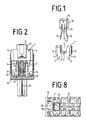
- the voltage limiter 10 consists of a rectangular housing with three connecting legs 12, 13 arranged on the bottom side 11 of the housing.
- the connecting legs 12, 13 are arranged one behind the other in a row, the middle connecting leg 13 being exactly centered on the two end faces of the voltage limiter 10 is arranged. All three connecting legs 12, 13 are each electrically connected to an electrical pole inside the voltage limiter 10.
- the plug receptacle 1 shown in Fig. 1 consists of a rectangular housing body made of plastic.
- the plug-in receptacle 1 has a free space 3 on the inside, the inner contour of which corresponds to the outer contour of the surge arrester 10.
- On the bottom side 4 of the socket 1 are As also shown in FIGS.
- FIG. 2 shows a surge arrester magazine 16 with a voltage limiter 10 inserted, which is accommodated in the plug receptacle 1.
- the surge arrester magazine 16 has a centrally arranged earth rail 14 which is fork-shaped in cross section. Upright plug elements 17 are arranged in the housing of the surge arrester magazine 16 on both sides of the earth rail 14 and are connected to plug tongues 20 which extend out of the housing.
- the surge arrester magazine 16 is inserted into a terminal block (not shown), the tabs 20 are connected to contact receptacles arranged in the terminal block.
- the contacts are made in one piece with insulation displacement contacts to which cable wires are connected.
- FIG. 8 shows the surge arrester magazine 16 in a top view, the chambers 21 which are open at the top being recognizable lying side by side. 8 shows a plug-in receptacle 1 inserted into the chamber 21 in the left-hand chamber 21.
- the inner contour of the chamber 21 corresponds to the outer contour of the plug receptacle 1.
- the voltage limiter 10 After inserting the Plug receptacle 1, the voltage limiter 10 is inserted from above into the plug receptacle 1, the connecting legs 12, 13 of the voltage limiter being inserted into the openings 5, 6 of the plug receptacle 1 until the connecting legs 12, 13 are in electrical connection with the earth rail 14 and the Plug elements 17 are brought.
- the two guide webs 2 give the two outer connecting legs 13 a guide so that the connecting legs 13 can be fed exactly without damage.
- the voltage limiter 10 has a stable position after being plugged into the plug receptacle 1, since the housing body of the voltage limiter 10 is completely enclosed by the plug receptacle 1.
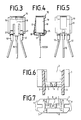
- the voltage limiter 10 can also be equipped with a thermal protection 15, as is shown in particular in FIGS. 3 to 5.
- the heat protection 15 consists of a U-shaped bow spring, the first leg end 18 of which makes a contact connection with the central connecting leg 12 and the second leg end 17 of which is kept at a distance from the outer connecting legs 13 by a melting element 19. Furthermore, 18 holding elements 22 are provided on the leg ends, which rest on the bottom side 11 of the voltage limiter 10 and the clamp spring is clamped to the voltage limiter 10.
- the plug-in receptacle 1 is provided with a clearance 8 so that the bow spring 20 is received in the plug-in receptacle 1 in the free space 8 when the voltage limiter 10 is inserted, as shown in FIG. 8.
Landscapes
- Emergency Protection Circuit Devices (AREA)
- Control Of Eletrric Generators (AREA)
- Thermistors And Varistors (AREA)
- Ignition Installations For Internal Combustion Engines (AREA)
- Tone Control, Compression And Expansion, Limiting Amplitude (AREA)
Applications Claiming Priority (2)
| Application Number | Priority Date | Filing Date | Title |
|---|---|---|---|
| DE9001687U | 1990-02-09 | ||
| DE9001687U DE9001687U1 (de) | 1990-02-09 | 1990-02-09 | Spannungsbegrenzer |
Publications (3)
| Publication Number | Publication Date |
|---|---|
| EP0440905A2 true EP0440905A2 (fr) | 1991-08-14 |
| EP0440905A3 EP0440905A3 (en) | 1991-10-09 |
| EP0440905B1 EP0440905B1 (fr) | 1995-08-30 |
Family
ID=6850986
Family Applications (1)
| Application Number | Title | Priority Date | Filing Date |
|---|---|---|---|
| EP90122922A Expired - Lifetime EP0440905B1 (fr) | 1990-02-09 | 1990-11-30 | Limiteur de tension |
Country Status (11)
| Country | Link |
|---|---|
| US (1) | US5172295A (fr) |
| EP (1) | EP0440905B1 (fr) |
| AT (1) | ATE127289T1 (fr) |
| AU (1) | AU655916B2 (fr) |
| BR (1) | BR9100513A (fr) |
| DE (2) | DE9001687U1 (fr) |
| DK (1) | DK0440905T3 (fr) |
| ES (1) | ES2076281T3 (fr) |
| GR (1) | GR3017322T3 (fr) |
| MX (1) | MX173728B (fr) |
| TR (1) | TR24932A (fr) |
Cited By (1)
| Publication number | Priority date | Publication date | Assignee | Title |
|---|---|---|---|---|
| CN107452455A (zh) * | 2016-04-13 | 2017-12-08 | 西门子公司 | 避雷器 |
Families Citing this family (13)
| Publication number | Priority date | Publication date | Assignee | Title |
|---|---|---|---|---|
| FR2671671A1 (fr) * | 1991-01-10 | 1992-07-17 | Mars Actel | Reglette de raccordement a protections semi-integrees. |
| DE4118738C1 (fr) * | 1991-06-05 | 1992-12-24 | Krone Ag, 1000 Berlin, De | |
| DE9115729U1 (de) * | 1991-12-19 | 1992-02-20 | Dehn + Söhne GmbH + Co KG, 8500 Nürnberg | Anordnung mit einer BCU-Einheit und mit Mitteln zum lösbaren Anschluß von BUS-Leitungen |
| SE514854C2 (sv) * | 1994-04-12 | 2001-05-07 | Ericsson Telefon Ab L M | Anordning för indikering av säkringsfel |
| US5781394A (en) * | 1997-03-10 | 1998-07-14 | Fiskars Inc. | Surge suppressing device |
| USD424022S (en) * | 1998-03-17 | 2000-05-02 | Krone Aktiengesellschaft | Surge arrester magazine |
| DE102005029012B3 (de) * | 2005-06-21 | 2006-12-28 | Adc Gmbh | Schutzstecker für Verteilereinrichtungen der Telekommunikations- und Datentechnik |
| USD591691S1 (en) | 2007-02-28 | 2009-05-05 | Adc Telecommunications, Inc. | Overvoltage protection plug |
| US8064182B2 (en) * | 2007-02-28 | 2011-11-22 | Adc Telecommunications, Inc. | Overvoltage protection plug |
| US7946863B2 (en) | 2008-04-25 | 2011-05-24 | Adc Telecommunications, Inc. | Circuit protection block |
| US8411404B2 (en) * | 2008-05-27 | 2013-04-02 | Adc Telecommunications, Inc. | Overvoltage protection plug |
| USD620896S1 (en) | 2008-05-27 | 2010-08-03 | Adc Telecommunications, Inc. | Overvoltage protection plug |
| WO2012108932A1 (fr) * | 2011-02-10 | 2012-08-16 | Phoenix Contact Development & Manufacturing, Inc. | Système de protection contre les surtensions enfichable |
Family Cites Families (7)
| Publication number | Priority date | Publication date | Assignee | Title |
|---|---|---|---|---|
| DE1299758B (de) * | 1962-04-27 | 1969-07-24 | Siemens Ag | Vorrichtung zur Aufnahme von knoppfoermigen UEberspannungsableitern |
| CH400311A (de) * | 1963-06-11 | 1965-10-15 | Bbc Brown Boveri & Cie | Verfahren, um das Drehzahlverhältnis zwischen einem Leitmotor und einem Antriebsmotor zu regeln und konstant zu halten, sowie Einrichtung zur Ausführung dieses Verfahrens |
| US4254301A (en) * | 1979-03-19 | 1981-03-03 | Xerox Corporation | Printed circuit board component mounting support and spacer |
| US4319300A (en) * | 1979-11-13 | 1982-03-09 | Tii Industries, Inc. | Surge arrester assembly |
| DE3014796C2 (de) * | 1980-04-17 | 1989-09-21 | Krone Gmbh, 1000 Berlin | Überspannungsableitervorrichtung für Anschlußleisten der Fernmeldetechnik |
| DE3323687C2 (de) * | 1983-07-01 | 1986-12-18 | Krone Gmbh, 1000 Berlin | Überspannungsableitermagazin für Anschlußleisten der Fernmeldetechnik |
| DE8910382U1 (de) * | 1989-08-31 | 1989-10-19 | CP Clare Corp., Beverly, Mass. | Knopfableiter |
-
1990
- 1990-02-09 DE DE9001687U patent/DE9001687U1/de not_active Expired - Lifetime
- 1990-11-30 AT AT90122922T patent/ATE127289T1/de not_active IP Right Cessation
- 1990-11-30 EP EP90122922A patent/EP0440905B1/fr not_active Expired - Lifetime
- 1990-11-30 DE DE59009584T patent/DE59009584D1/de not_active Expired - Fee Related
- 1990-11-30 ES ES90122922T patent/ES2076281T3/es not_active Expired - Fee Related
- 1990-11-30 DK DK90122922.9T patent/DK0440905T3/da active
- 1990-12-13 MX MX023718A patent/MX173728B/es unknown
-
1991
- 1991-01-02 AU AU68654/91A patent/AU655916B2/en not_active Ceased
- 1991-01-24 US US07/645,467 patent/US5172295A/en not_active Expired - Fee Related
- 1991-02-06 BR BR919100513A patent/BR9100513A/pt not_active IP Right Cessation
- 1991-02-07 TR TR91/0116A patent/TR24932A/xx unknown
-
1995
- 1995-09-06 GR GR950402452T patent/GR3017322T3/el unknown
Cited By (2)
| Publication number | Priority date | Publication date | Assignee | Title |
|---|---|---|---|---|
| CN107452455A (zh) * | 2016-04-13 | 2017-12-08 | 西门子公司 | 避雷器 |
| CN107452455B (zh) * | 2016-04-13 | 2020-03-06 | 西门子公司 | 避雷器 |
Also Published As
| Publication number | Publication date |
|---|---|
| US5172295A (en) | 1992-12-15 |
| AU655916B2 (en) | 1995-01-19 |
| ES2076281T3 (es) | 1995-11-01 |
| MX173728B (es) | 1994-03-23 |
| TR24932A (tr) | 1992-07-01 |
| DE59009584D1 (de) | 1995-10-05 |
| AU6865491A (en) | 1991-08-15 |
| ATE127289T1 (de) | 1995-09-15 |
| DE9001687U1 (de) | 1990-04-12 |
| BR9100513A (pt) | 1991-10-29 |
| DK0440905T3 (da) | 1995-09-25 |
| EP0440905A3 (en) | 1991-10-09 |
| GR3017322T3 (en) | 1995-12-31 |
| EP0440905B1 (fr) | 1995-08-30 |
Similar Documents
| Publication | Publication Date | Title |
|---|---|---|
| EP0382322B1 (fr) | Réglette de raccordement | |
| DE3876646T2 (de) | Elektrische anschlussklemme. | |
| EP0272200B1 (fr) | Bloc de connexion pour les télécommunications | |
| DE3807645A1 (de) | Steckverbindungssystem fuer elektrische leiter | |
| DE3320147A1 (de) | Hf-filter-steckerverbindung | |
| EP0388585A2 (fr) | Connecteur de protection pour barrette de connexion pour technique de télécommunication et de traitement de données | |
| DE102004040834B3 (de) | Steckkontakt | |
| EP0440905B1 (fr) | Limiteur de tension | |
| EP0338187A2 (fr) | Fiche de protection pour boîters d'interuption ou de disjonction | |
| DE3306263C2 (fr) | ||
| DE4102784C2 (de) | Anschlußklemme | |
| DE19547557A1 (de) | Elektrische Klemmen mit steckbaren Querbrückern | |
| EP0706235A2 (fr) | Cosse femelle verrouillable pour une connexion électrique | |
| DE3028809C2 (de) | Steckeranordnung zur Aufnahme eines Flachsteckers | |
| DE7525722U (de) | Kontaktelement | |
| DE2348992A1 (de) | Elektrischer verbinder | |
| EP0477663B1 (fr) | Pièce de contact | |
| DE3241177A1 (de) | Sicherungs-reihenklemme | |
| DE3030523A1 (de) | Elektrische anschlussklemme | |
| EP1020954B1 (fr) | Borne de connexion électrique | |
| DE3103455C2 (de) | Elektrischer Steckverbinder, insbesondere der Datentechnik | |
| EP0738026B1 (fr) | Ressort de contact | |
| EP0704942A2 (fr) | Bloc de connexion électrique | |
| DE2700793A1 (de) | Verbindungsklemme zur stromuebertragung von elektrischen leitern | |
| DE1954997C3 (de) | Elektrische Steckvorrichtung |
Legal Events
| Date | Code | Title | Description |
|---|---|---|---|
| PUAI | Public reference made under article 153(3) epc to a published international application that has entered the european phase |
Free format text: ORIGINAL CODE: 0009012 |
|
| AK | Designated contracting states |
Kind code of ref document: A2 Designated state(s): AT BE CH DE DK ES FR GB GR IT LI LU NL SE |
|
| PUAL | Search report despatched |
Free format text: ORIGINAL CODE: 0009013 |
|
| AK | Designated contracting states |
Kind code of ref document: A3 Designated state(s): AT BE CH DE DK ES FR GB GR IT LI LU NL SE |
|
| 17P | Request for examination filed |
Effective date: 19910824 |
|
| 17Q | First examination report despatched |
Effective date: 19940727 |
|
| GRAA | (expected) grant |
Free format text: ORIGINAL CODE: 0009210 |
|
| AK | Designated contracting states |
Kind code of ref document: B1 Designated state(s): AT BE CH DE DK ES FR GB GR IT LI LU NL SE |
|
| REF | Corresponds to: |
Ref document number: 127289 Country of ref document: AT Date of ref document: 19950915 Kind code of ref document: T |
|
| ITF | It: translation for a ep patent filed | ||
| REG | Reference to a national code |
Ref country code: DK Ref legal event code: T3 |
|
| GBT | Gb: translation of ep patent filed (gb section 77(6)(a)/1977) |
Effective date: 19950829 |
|
| ET | Fr: translation filed | ||
| REF | Corresponds to: |
Ref document number: 59009584 Country of ref document: DE Date of ref document: 19951005 |
|
| REG | Reference to a national code |
Ref country code: ES Ref legal event code: FG2A Ref document number: 2076281 Country of ref document: ES Kind code of ref document: T3 |
|
| REG | Reference to a national code |
Ref country code: GR Ref legal event code: FG4A Free format text: 3017322 |
|
| PLBE | No opposition filed within time limit |
Free format text: ORIGINAL CODE: 0009261 |
|
| STAA | Information on the status of an ep patent application or granted ep patent |
Free format text: STATUS: NO OPPOSITION FILED WITHIN TIME LIMIT |
|
| 26N | No opposition filed | ||
| PGFP | Annual fee paid to national office [announced via postgrant information from national office to epo] |
Ref country code: GB Payment date: 19991112 Year of fee payment: 10 |
|
| PGFP | Annual fee paid to national office [announced via postgrant information from national office to epo] |
Ref country code: ES Payment date: 19991118 Year of fee payment: 10 |
|
| PGFP | Annual fee paid to national office [announced via postgrant information from national office to epo] |
Ref country code: DK Payment date: 19991122 Year of fee payment: 10 |
|
| PGFP | Annual fee paid to national office [announced via postgrant information from national office to epo] |
Ref country code: FR Payment date: 19991123 Year of fee payment: 10 Ref country code: BE Payment date: 19991123 Year of fee payment: 10 Ref country code: AT Payment date: 19991123 Year of fee payment: 10 |
|
| PGFP | Annual fee paid to national office [announced via postgrant information from national office to epo] |
Ref country code: SE Payment date: 19991124 Year of fee payment: 10 |
|
| PGFP | Annual fee paid to national office [announced via postgrant information from national office to epo] |
Ref country code: CH Payment date: 19991125 Year of fee payment: 10 |
|
| PGFP | Annual fee paid to national office [announced via postgrant information from national office to epo] |
Ref country code: GR Payment date: 19991129 Year of fee payment: 10 |
|
| PGFP | Annual fee paid to national office [announced via postgrant information from national office to epo] |
Ref country code: NL Payment date: 19991130 Year of fee payment: 10 |
|
| PGFP | Annual fee paid to national office [announced via postgrant information from national office to epo] |
Ref country code: DE Payment date: 19991210 Year of fee payment: 10 |
|
| PGFP | Annual fee paid to national office [announced via postgrant information from national office to epo] |
Ref country code: LU Payment date: 20000110 Year of fee payment: 10 |
|
| PG25 | Lapsed in a contracting state [announced via postgrant information from national office to epo] |
Ref country code: LU Free format text: LAPSE BECAUSE OF NON-PAYMENT OF DUE FEES Effective date: 20001130 Ref country code: LI Free format text: LAPSE BECAUSE OF NON-PAYMENT OF DUE FEES Effective date: 20001130 Ref country code: GR Free format text: LAPSE BECAUSE OF NON-PAYMENT OF DUE FEES Effective date: 20001130 Ref country code: GB Free format text: LAPSE BECAUSE OF NON-PAYMENT OF DUE FEES Effective date: 20001130 Ref country code: DK Free format text: LAPSE BECAUSE OF NON-PAYMENT OF DUE FEES Effective date: 20001130 Ref country code: CH Free format text: LAPSE BECAUSE OF NON-PAYMENT OF DUE FEES Effective date: 20001130 Ref country code: BE Free format text: LAPSE BECAUSE OF NON-PAYMENT OF DUE FEES Effective date: 20001130 Ref country code: AT Free format text: LAPSE BECAUSE OF NON-PAYMENT OF DUE FEES Effective date: 20001130 |
|
| PG25 | Lapsed in a contracting state [announced via postgrant information from national office to epo] |
Ref country code: SE Free format text: LAPSE BECAUSE OF NON-PAYMENT OF DUE FEES Effective date: 20001201 Ref country code: ES Free format text: LAPSE BECAUSE OF NON-PAYMENT OF DUE FEES Effective date: 20001201 |
|
| BERE | Be: lapsed |
Owner name: KRONE A.G. Effective date: 20001130 |
|
| PG25 | Lapsed in a contracting state [announced via postgrant information from national office to epo] |
Ref country code: NL Free format text: LAPSE BECAUSE OF NON-PAYMENT OF DUE FEES Effective date: 20010601 |
|
| REG | Reference to a national code |
Ref country code: CH Ref legal event code: PL |
|
| GBPC | Gb: european patent ceased through non-payment of renewal fee |
Effective date: 20001130 |
|
| REG | Reference to a national code |
Ref country code: DK Ref legal event code: EBP |
|
| PG25 | Lapsed in a contracting state [announced via postgrant information from national office to epo] |
Ref country code: FR Free format text: LAPSE BECAUSE OF NON-PAYMENT OF DUE FEES Effective date: 20010731 |
|
| NLV4 | Nl: lapsed or anulled due to non-payment of the annual fee |
Effective date: 20010601 |
|
| PG25 | Lapsed in a contracting state [announced via postgrant information from national office to epo] |
Ref country code: DE Free format text: LAPSE BECAUSE OF NON-PAYMENT OF DUE FEES Effective date: 20010801 |
|
| EUG | Se: european patent has lapsed |
Ref document number: 90122922.9 |
|
| REG | Reference to a national code |
Ref country code: FR Ref legal event code: ST |
|
| REG | Reference to a national code |
Ref country code: ES Ref legal event code: FD2A Effective date: 20011214 |
|
| PG25 | Lapsed in a contracting state [announced via postgrant information from national office to epo] |
Ref country code: IT Free format text: LAPSE BECAUSE OF NON-PAYMENT OF DUE FEES Effective date: 20051130 |