EP0440976A1 - Dispositif transportable pour l'enlèvement des dépôts d'obstructions des tuyaux sanitaires - Google Patents
Dispositif transportable pour l'enlèvement des dépôts d'obstructions des tuyaux sanitaires Download PDFInfo
- Publication number
- EP0440976A1 EP0440976A1 EP90125351A EP90125351A EP0440976A1 EP 0440976 A1 EP0440976 A1 EP 0440976A1 EP 90125351 A EP90125351 A EP 90125351A EP 90125351 A EP90125351 A EP 90125351A EP 0440976 A1 EP0440976 A1 EP 0440976A1
- Authority
- EP
- European Patent Office
- Prior art keywords
- container
- compressed air
- pipe
- shut
- riser pipe
- Prior art date
- Legal status (The legal status is an assumption and is not a legal conclusion. Google has not performed a legal analysis and makes no representation as to the accuracy of the status listed.)
- Withdrawn
Links
- 230000008021 deposition Effects 0.000 title 1
- 238000000151 deposition Methods 0.000 title 1
- 238000011010 flushing procedure Methods 0.000 claims abstract description 30
- 239000007788 liquid Substances 0.000 claims description 21
- 230000008878 coupling Effects 0.000 claims description 5
- 238000010168 coupling process Methods 0.000 claims description 5
- 238000005859 coupling reaction Methods 0.000 claims description 5
- 210000000078 claw Anatomy 0.000 claims description 2
- 239000012530 fluid Substances 0.000 abstract 3
- XLYOFNOQVPJJNP-UHFFFAOYSA-N water Substances O XLYOFNOQVPJJNP-UHFFFAOYSA-N 0.000 description 12
- 238000004140 cleaning Methods 0.000 description 11
- 239000003638 chemical reducing agent Substances 0.000 description 2
- 210000002445 nipple Anatomy 0.000 description 2
- 238000007789 sealing Methods 0.000 description 2
- 230000006978 adaptation Effects 0.000 description 1
- 238000011109 contamination Methods 0.000 description 1
- 238000011161 development Methods 0.000 description 1
- 230000018109 developmental process Effects 0.000 description 1
- 230000000694 effects Effects 0.000 description 1
- 238000010438 heat treatment Methods 0.000 description 1
- 230000000630 rising effect Effects 0.000 description 1
- 230000035939 shock Effects 0.000 description 1
- 239000000126 substance Substances 0.000 description 1
Images

Classifications
-
- E—FIXED CONSTRUCTIONS
- E03—WATER SUPPLY; SEWERAGE
- E03C—DOMESTIC PLUMBING INSTALLATIONS FOR FRESH WATER OR WASTE WATER; SINKS
- E03C1/00—Domestic plumbing installations for fresh water or waste water; Sinks
- E03C1/12—Plumbing installations for waste water; Basins or fountains connected thereto; Sinks
- E03C1/30—Devices to facilitate removing of obstructions in waste-pipes or sinks
- E03C1/304—Devices to facilitate removing of obstructions in waste-pipes or sinks using fluid under pressure
Definitions
- the invention relates to a transportable device with which sanitary pipelines can be cleaned of deposits and blockages by means of compressed air and flushing liquid.
- Such a device has become known from DE-OS 1658175.
- the water column in front of the blockage point is pressurized with compressed air by quickly opening a shut-off device in a compressed air hose line. This creates so-called shock waves that remove the blockage.
- the rinsing liquid is taken from a water tap. An adaptation of the pressure of the rinsing liquid to different deposits and blockages is not provided.
- the object underlying the invention is that the device according to claim 1 is able to remove strongly adhering deposits and stubborn blockages in a short time regardless of a water tap and its line pressure.
- the pipe cleaning device is designed as a compact and easily portable hand-held device and has a container that can be filled with flushing liquid, which can be connected to the pipeline to be cleaned via a riser pipe and whose flushing liquid is pressed out of the container into the pipeline by compressed air.
- the flushing liquid thus flows once under pressure into the pipeline to be cleaned and, in addition to increasing the cleaning effect, compressed air is intermittently added to the flushing liquid outside the container, which increases the pressure of the flushing liquid and also tears and clogged deposits from the pipeline and flushed out .
- the compressed air is introduced into the container via a compressed air pipe and the other is brought directly into the pipe to be cleaned or the flushing line via the compressed air line, this additional compressed air supply being controlled by a manually operated shut-off device. It is also advantageous that the device according to the invention does not require a connection to a water tap and the flushing liquid pressure is variable.
- the entire device is simple and cost-effective, easy to transport to the place of work, to be connected to the pipeline to be cleaned via a quick coupling and to be connected to a compressed air generator.
- the device works perfectly due to the way it works with flushing liquid and additional compressed air.
- the transportable device for removing deposits and blockages in sanitary pipelines (1) has a container (3) which can be filled with a flushing liquid (2) as a pressure container.
- a riser pipe (4) is led out of this container (3), which has a connection (5) for the pipeline (1) to be cleaned or a flushing pipe (6).
- a compressed air line (7) is connected to the riser pipe (4), from which a compressed air pipe (8) led into the container (3) for pressing out the flushing liquid (2) goes out through the riser pipe (4) and into which a manually operated shut-off device (9 ) for intermittent release of the compressed air (20) into the flushing liquid (2) flowing out of the riser pipe (4).
- a T-piece (10) with a manometer (11) is also inserted, from which the compressed air pipe (8) goes out and opens into the neck (3a) of the container (3) next to the riser pipe (4).
- connection (5) of the riser pipe (4) is formed by a quick coupling to which the flushing pipe (6) which can be inserted into the pipe (1) to be cleaned or the pipe (1) to be cleaned can be connected directly.
- the container (3) has an outlet (13) in the bottom area, such as a valve, tap, or the like.
- the container (3) is or is filled on-site via its connection (5) with the rinsing liquid (2), which can be formed by cold water, hot water or chemical liquid, which flows through the riser pipe (4) into the container (3) can flow in.
- the rinsing liquid (2) which can be formed by cold water, hot water or chemical liquid, which flows through the riser pipe (4) into the container (3) can flow in.
- the portable pipe cleaning device is connected on site with the compressed air line (7) to a compressed air generator (compressor).
- compressor compressed air generator
- the flushing line (6) is connected to the connection (5) and introduced into the pipeline (1) to be cleaned, an inflatable bellows for sealing the pipeline (1) being able to be attached to the flushing line (6) so that the flushing liquid (2) can't fight back.
- shut-off valve (17) of the assembly (19) is opened and the compressed air (20) flows in the direction "A" through the compressed air line (7) to the shut-off device (9) and via the compressed air pipe (8) into the container (3 ) and acts on the flushing liquid (2), which then flows up through the riser pipe (4) into the flushing line (6) and enters the pipeline (1) under pressure, which causes the pipeline (1) to be flushed through and cleaned.
- the shut-off device (9) is then briefly opened by hand at certain time intervals, as a result of which the pressure in the flushing liquid (2) is increased by the additional compressed air (20) and also strongly adhering deposits or severe blockages the pipe (1) are torn out and washed away.
- the removal of the blockages can be recognized on the manometer (11) depending on the pressure display.
- a suction cup or another sealing part can be connected to the flushing line (6).
- the pipe cleaning device is preferably designed to be detachable from its container (3) in that a cover (21) is detachably fixed on the container neck (3a), for example by a bayonet or screw lock. With this cover (21), the two pipes (4, 8) are connected to form a unit, and the riser pipe (4) can be separated below the cover (21), for example by screw connection (22), plug connection, or the like. , executed.
- the pipe cleaning device can also be used for pressing containers of various types.
- a shut-off valve or tap (23) is inserted into the compressed air pipe (8).
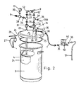
- the cleaning device shown in FIG. 2 corresponds in basic structure and in the function of the device according to FIG. 1, and the same reference numbers have been used for the same parts.
- a removable plastic bucket (24) is inserted into the container (3) and the container (3) is releasably closed by a cover (25) with the interposition of a seal (26) by means of clamping claws (27) with toggle screws (28).
- the cover (25) has connecting pieces (29, 30) for one shut-off device (31, 32) (ball valve), with the rising pipe (4) being connected to the connecting piece (29) and the connecting piece (30) for the compressed air supply in serves the container (3).
- Both shut-off devices (31, 32) are detachably fastened to their connections (29, 30) by screw connections, not shown.
- a T-piece (34) with a safety valve (35) is connected to a further connecting piece (33) of the cover (25) and the T-piece (34) has a quick relief valve (36a), by means of which pressure relief in the container ( 3) can be carried out or, if the pressure in the container (3) is too high, the pressure relief valve (36a) automatically releases the pressure as security.
- Both shut-off devices (31, 32) are each connected to a T-piece (37, 38) via a connecting piece (nipple) (36), the T-piece (37) being connected to a further T-piece (39), from which the connection (5) for the line (1) goes and which carries a manometer (11).
- the compressed air line (7) can be connected to the other T-piece (38) via a connecting piece (36), which has a pressure indicator (40) with a pressure reducer (50), on which the connecting line (51) leading to a compressor goes out.
- the two T-pieces (37, 38) are each coupled with an angle piece (52), between which a shut-off device (9) (ball valve) is inserted.
- a shut-off device (9) ball valve
- the compressed air can flow through the T-piece (38) and the open ball valve (32) as well as the T-piece (34) into the container (3) and the water from the riser pipe (4) open ball valve (31) and flow through the T-pieces (37, 39) into the flushing line (1); the ball valve (9) is closed
- the pressure indicator (40) indicates the pressure in the container (3).
- the manometer (11) can be used to determine how quickly the pressure on the manometer (11) drops and whether the blockage has been removed or still exists.
- shut-off device (9) If the shut-off device (9) is placed in the tilted position (in a slightly open position), the main air pressure goes through the T-piece (38) and the opened shut-off device (32) into the container (3) and presses the water through the riser pipe (4 ) high and at the same time a portion of air is added to the water in the flushing line via the T-piece (37) through this shut-off device (9).
Landscapes
- Engineering & Computer Science (AREA)
- Environmental & Geological Engineering (AREA)
- Health & Medical Sciences (AREA)
- Life Sciences & Earth Sciences (AREA)
- Hydrology & Water Resources (AREA)
- Public Health (AREA)
- Water Supply & Treatment (AREA)
- Cleaning In General (AREA)
Priority Applications (1)
| Application Number | Priority Date | Filing Date | Title |
|---|---|---|---|
| AU72112/91A AU7211291A (en) | 1990-02-07 | 1991-02-01 | Transportable device for removing deposits and blockages in sanitary pipes |
Applications Claiming Priority (2)
| Application Number | Priority Date | Filing Date | Title |
|---|---|---|---|
| DE4003635 | 1990-02-07 | ||
| DE19904003635 DE4003635C1 (en) | 1990-02-07 | 1990-02-07 | Sanitation pipe cleaner - flushes liq. from refillable container via flushing pipe, and air via compressed air pipe |
Publications (1)
| Publication Number | Publication Date |
|---|---|
| EP0440976A1 true EP0440976A1 (fr) | 1991-08-14 |
Family
ID=6399617
Family Applications (1)
| Application Number | Title | Priority Date | Filing Date |
|---|---|---|---|
| EP90125351A Withdrawn EP0440976A1 (fr) | 1990-02-07 | 1990-12-22 | Dispositif transportable pour l'enlèvement des dépôts d'obstructions des tuyaux sanitaires |
Country Status (3)
| Country | Link |
|---|---|
| EP (1) | EP0440976A1 (fr) |
| DE (1) | DE4003635C1 (fr) |
| WO (1) | WO1991012380A1 (fr) |
Cited By (1)
| Publication number | Priority date | Publication date | Assignee | Title |
|---|---|---|---|---|
| DE202008004389U1 (de) * | 2008-03-31 | 2009-08-06 | Böhm, Rolf | Vorrichtung zum Entfernen von Verstopfungen in Flugzeug Toiletten, Vakuum-Rohrleitungs-Systemen |
Families Citing this family (3)
| Publication number | Priority date | Publication date | Assignee | Title |
|---|---|---|---|---|
| DE4432503C2 (de) * | 1994-09-13 | 1998-09-03 | Behr Industrietech Gmbh & Co | Verfahren zum Reinigen der Hohlkörper eines Wärmetauschers und Vorrichtung zur Durchführung des Verfahrens |
| GB2353580B (en) * | 1999-08-26 | 2003-01-29 | George Patrick Locke | Blockage buster |
| DE102007004278A1 (de) * | 2007-01-23 | 2008-07-24 | Clepsys Gbr (Vertungsberechtigte Gesellschafter:Christian Bies | System zur Reinigung von Abwasserleitungen |
Citations (4)
| Publication number | Priority date | Publication date | Assignee | Title |
|---|---|---|---|---|
| US2771891A (en) * | 1955-08-18 | 1956-11-27 | Palley Zoltan O St | Apparatus for cleaning pipe lines |
| US2835261A (en) * | 1956-11-15 | 1958-05-20 | Selmer F Wogan | Portable liquid line flushing device |
| US4229852A (en) * | 1978-11-22 | 1980-10-28 | Brobeck Glenn H | Portable pipe cleaning apparatus |
| FR2602571A1 (fr) * | 1986-08-06 | 1988-02-12 | Assainissement Rationnel Pompa | Procede de nettoyage d'une conduite notamment d'un reseau de distribution d'eau potable et systeme pour la mise en oeuvre de ce procede |
Family Cites Families (1)
| Publication number | Priority date | Publication date | Assignee | Title |
|---|---|---|---|---|
| DE1658175A1 (de) * | 1967-03-04 | 1970-03-05 | Josef Antoszkiewicz | Vorrichtung zur Reinigung von Abflussleitungen |
-
1990
- 1990-02-07 DE DE19904003635 patent/DE4003635C1/de not_active Expired - Lifetime
- 1990-12-22 EP EP90125351A patent/EP0440976A1/fr not_active Withdrawn
-
1991
- 1991-02-01 WO PCT/EP1991/000186 patent/WO1991012380A1/fr not_active Ceased
Patent Citations (4)
| Publication number | Priority date | Publication date | Assignee | Title |
|---|---|---|---|---|
| US2771891A (en) * | 1955-08-18 | 1956-11-27 | Palley Zoltan O St | Apparatus for cleaning pipe lines |
| US2835261A (en) * | 1956-11-15 | 1958-05-20 | Selmer F Wogan | Portable liquid line flushing device |
| US4229852A (en) * | 1978-11-22 | 1980-10-28 | Brobeck Glenn H | Portable pipe cleaning apparatus |
| FR2602571A1 (fr) * | 1986-08-06 | 1988-02-12 | Assainissement Rationnel Pompa | Procede de nettoyage d'une conduite notamment d'un reseau de distribution d'eau potable et systeme pour la mise en oeuvre de ce procede |
Cited By (3)
| Publication number | Priority date | Publication date | Assignee | Title |
|---|---|---|---|---|
| DE202008004389U1 (de) * | 2008-03-31 | 2009-08-06 | Böhm, Rolf | Vorrichtung zum Entfernen von Verstopfungen in Flugzeug Toiletten, Vakuum-Rohrleitungs-Systemen |
| DE102009014415A1 (de) | 2008-03-31 | 2009-12-03 | Böhm, Rolf | Vorrichtung zum Beseitigen von Verstopfungen in Flugzeug-Vakuum-Toilettenanlagen |
| DE102009014415B4 (de) * | 2008-03-31 | 2011-12-29 | Rolf Böhm | Vorrichtung zum Beseitigen von Verstopfungen in Flugzeug-Vakuum-Toilettenanlagen |
Also Published As
| Publication number | Publication date |
|---|---|
| WO1991012380A1 (fr) | 1991-08-22 |
| DE4003635C1 (en) | 1991-06-06 |
Similar Documents
| Publication | Publication Date | Title |
|---|---|---|
| DE69722804T2 (de) | Stapelbarer behälter und system zum entfernen von zahnstein | |
| DE10204737B4 (de) | Vorrichtung zum Spülen und Reinigen einer Rohrleitung, insbesondere einer Trinkwasserleitung | |
| DE3722549A1 (de) | Einrichtung zur spuelung und reinigung einer rohrleitung | |
| DE69908174T2 (de) | Verfahren und gerät zum reinigen industrieller rohrsysteme | |
| EP0440976A1 (fr) | Dispositif transportable pour l'enlèvement des dépôts d'obstructions des tuyaux sanitaires | |
| EP3464164B1 (fr) | Système de remplissage de cuves avec récipient intermédiaire | |
| DE4420579A1 (de) | Verfahren zum Reinigen von Rohrleitungen | |
| DE10234407A1 (de) | Spülflüssigkeitsaufbereitungsgerät | |
| DE102009032790A1 (de) | Spüleinrichtung | |
| DE102016110009A1 (de) | Vorrichtung zur Befüllung von Tanks mit Zwischenbehälter | |
| DE102017105418B4 (de) | Vorrichtung zur Befüllung von Tanks mit Zwischenbehälter | |
| AT358417B (de) | Hochdruck-waschlanze | |
| WO2018234036A1 (fr) | Tête de raccordement et nœuds de vannes | |
| DE202005011349U1 (de) | In einem Tank verfahrbares Fahrzeug | |
| DE102005058674B4 (de) | Zusatzvorrichtung für ein Arbeitsmittel, insbesondere eine Spirale, zur Beseitigung einer Verstopfung in einer Abflussleitung | |
| DE102017105419A1 (de) | Vorrichtung zur Befüllung von Tanks mit Zwischenbehälter | |
| DE3843418A1 (de) | Einrichtung zum ansaugen von fluessigkeit | |
| DE102017105417B4 (de) | Vorrichtung zur Befüllung von Tanks mit Zwischenbehälter | |
| DE301816C (fr) | ||
| DE889114C (de) | Vorrichtung zum Zumischen eines Schaummittels in die Druckwasserleitung von Feuerloeschanlagen | |
| DE365506C (de) | Vorrichtung zum Reinigen von Rohrleitungen, insbesondere von Bierleitungen, mit einem Behaelter mittels einer unter Druck stehenden Reinigungsmasse | |
| DE482474C (de) | Vorrichtung zum Reinigen von Rohrleitungen, insbesondere Bierleitungen | |
| DE309606C (fr) | ||
| DE261910C (fr) | ||
| DE102009008561B3 (de) | Vorrichtung zum Druckstrahlen |
Legal Events
| Date | Code | Title | Description |
|---|---|---|---|
| PUAI | Public reference made under article 153(3) epc to a published international application that has entered the european phase |
Free format text: ORIGINAL CODE: 0009012 |
|
| AK | Designated contracting states |
Kind code of ref document: A1 Designated state(s): AT BE CH DE DK ES FR GB GR IT LI LU NL SE |
|
| 17P | Request for examination filed |
Effective date: 19920212 |
|
| 17Q | First examination report despatched |
Effective date: 19920514 |
|
| STAA | Information on the status of an ep patent application or granted ep patent |
Free format text: STATUS: THE APPLICATION IS DEEMED TO BE WITHDRAWN |
|
| 18D | Application deemed to be withdrawn |
Effective date: 19930112 |