EP0441015A1 - Joint d'étanchéité annulaire - Google Patents
Joint d'étanchéité annulaire Download PDFInfo
- Publication number
- EP0441015A1 EP0441015A1 EP90301264A EP90301264A EP0441015A1 EP 0441015 A1 EP0441015 A1 EP 0441015A1 EP 90301264 A EP90301264 A EP 90301264A EP 90301264 A EP90301264 A EP 90301264A EP 0441015 A1 EP0441015 A1 EP 0441015A1
- Authority
- EP
- European Patent Office
- Prior art keywords
- sealing
- annular
- arch
- seal
- members
- Prior art date
- Legal status (The legal status is an assumption and is not a legal conclusion. Google has not performed a legal analysis and makes no representation as to the accuracy of the status listed.)
- Granted
Links
- 238000007789 sealing Methods 0.000 title claims abstract description 93
- 239000002184 metal Substances 0.000 claims description 10
- 239000012530 fluid Substances 0.000 claims description 9
- 210000004907 gland Anatomy 0.000 claims description 5
- 230000009977 dual effect Effects 0.000 description 2
- 230000000717 retained effect Effects 0.000 description 2
- 241001474728 Satyrodes eurydice Species 0.000 description 1
- 239000002783 friction material Substances 0.000 description 1
- 239000000314 lubricant Substances 0.000 description 1
- 238000012856 packing Methods 0.000 description 1
- 238000007790 scraping Methods 0.000 description 1
Images


Classifications
-
- F—MECHANICAL ENGINEERING; LIGHTING; HEATING; WEAPONS; BLASTING
- F16—ENGINEERING ELEMENTS AND UNITS; GENERAL MEASURES FOR PRODUCING AND MAINTAINING EFFECTIVE FUNCTIONING OF MACHINES OR INSTALLATIONS; THERMAL INSULATION IN GENERAL
- F16J—PISTONS; CYLINDERS; SEALINGS
- F16J15/00—Sealings
- F16J15/16—Sealings between relatively-moving surfaces
- F16J15/32—Sealings between relatively-moving surfaces with elastic sealings, e.g. O-rings
- F16J15/3284—Sealings between relatively-moving surfaces with elastic sealings, e.g. O-rings characterised by their structure; Selection of materials
-
- F—MECHANICAL ENGINEERING; LIGHTING; HEATING; WEAPONS; BLASTING
- F16—ENGINEERING ELEMENTS AND UNITS; GENERAL MEASURES FOR PRODUCING AND MAINTAINING EFFECTIVE FUNCTIONING OF MACHINES OR INSTALLATIONS; THERMAL INSULATION IN GENERAL
- F16J—PISTONS; CYLINDERS; SEALINGS
- F16J15/00—Sealings
- F16J15/16—Sealings between relatively-moving surfaces
- F16J15/26—Sealings between relatively-moving surfaces with stuffing-boxes for rigid sealing rings
- F16J15/28—Sealings between relatively-moving surfaces with stuffing-boxes for rigid sealing rings with sealing rings made of metal
-
- Y—GENERAL TAGGING OF NEW TECHNOLOGICAL DEVELOPMENTS; GENERAL TAGGING OF CROSS-SECTIONAL TECHNOLOGIES SPANNING OVER SEVERAL SECTIONS OF THE IPC; TECHNICAL SUBJECTS COVERED BY FORMER USPC CROSS-REFERENCE ART COLLECTIONS [XRACs] AND DIGESTS
- Y10—TECHNICAL SUBJECTS COVERED BY FORMER USPC
- Y10S—TECHNICAL SUBJECTS COVERED BY FORMER USPC CROSS-REFERENCE ART COLLECTIONS [XRACs] AND DIGESTS
- Y10S277/00—Seal for a joint or juncture
- Y10S277/909—Similar sealing structures for mounting on piston and about rod
Definitions
- the present invention relates to an improved annular sealing structure or apparatus for sealing across the annulus between two members, such as the annulus surrounding a valve stem and within the packing gland surrounding the valve stem and the annulus within a tubular well string and surrounding the sealing assembly supported therein.
- the K. A. Morales U. S. Patent No. 4,302,020 discloses a toroidal sealing element for sealing between concentric facing cylindrical surfaces.
- the sealing element is U-shaped in section and includes an actuator ring having a tapered nose which engages within the gap of the sealing element to deflect its arms outward into sealing engagement with the inner and outer sealing surfaces.
- the J. E. Brown U. S. Patent No. 4,184,690 discloses an annular shaft seal which has two legs joined at an outer apex. The legs seal on their end surfaces against the shaft and on their outer surfaces against the cylinder and cap. Fluid passages are provided in the legs to provide pressure equalization across the seal.
- the T. P. Nicholson U. S. Patent No. 4,585,238 discloses a seal having a body with diverging legs and with an outer jacket of yieldable low friction material and an inner energizing spring between the legs.
- the L. S. Bialkowski U. S. Patent No. 3,279,806 discloses a U-shaped metal seal with legs having projections for sealing against inner and outer cylindrical sealing surfaces.
- the present invention includes an improved annular metal seal having a body with a pair of flanges and a tapering arch between the flanges and tapering so that its thinnest portion is at the midpoint of the arch.
- the annulus in which the improved seal of the present invention operates is between facing cylindrical surface on a first member and a second member. Sealing with a cylindrical sealing surface of the first member is provided by the convex side of the annular arch at its midpoint.
- the seal body is suitably supported and in sealing engagement with the second member.
- An object of the present invention is to provide an improved annular metal seal apparatus with improved sealing efficiency.
- a further object is to provide an improved annular metal seal apparatus which can seal against a reciprocating shaft without scraping the lubricant from the shaft.
- Another object is to provide an improved annular metal seal apparatus which is simple to install and has a relatively long service life.
- Actuator 10 illustrated in FIGURE 1 includes body 12 defining a piston chamber 14 in which piston 16 is positioned for reciprocation. Piston rod 18 extends through piston 16 and is secured in such position so that it moves with piston 16 to transmit the movement thereof to a device to which rod 18 is connected, such as a valve member or a blowout preventer ram (not shown). Body 12 is formed to have opening 20 at the end of chamber 14 and piston rod 18 extends through opening 20. Improved annular seal 22 is positioned in opening 20 for sealing between the interior wall of opening 20 and the exterior of piston rod 18.
- opening 20 includes a stepped bore having a first bore 24 closely surrounding the exterior of piston rod 18, second bore 26 spaced therefrom, third bore 28 providing shoulder 30, fourth bore 32 and fifth bore 34, all as hereinafter described.
- Improved annular seal 22 is positioned in second bore 26 and includes annular body 36 with first flange 38 positioned near the shoulder between first and second bores 24 and 26, second flange 40 spaced axially from first flange 36 and joined thereto by inwardly extending sealing arch 42, external seal lip 44 extending outwardly and upwardly from the exterior of second flange 40 for sealing against the inner surface of second bore 26 and collar 46 extending outwardly from second flange 40 and clamped against the shoulder 30 between second and third bores 26 and 28 by plug 48 which is threaded into fifth bore 34 and sealed within fourth bore 32 and against the exterior of rod 18.
- Sealing arch 42 is shaped to have thicker portions near flanges 38 and 40 and to become thinner toward its central portion.
- the convex side of arch 42 is adapted to provide sealing engagement with the interior of its central portion.
- Seal 22 is designed to have an interference fit between the interior of the seal arch 42 and the exterior of rod 18. With this configuration seal 22 is mechanically deformed due to the interference and also is further deformed by the fluid pressure from piston chamber 14 which is exerted on the exterior, concave side of seal 22. Seal lip 44 prevents the leakage of such pressure beyond the sealing engagement of seal lip 44 with the interior of second bore 26.
- the shape and reduced section of annular arch 42 makes it a flexible member having its minimum thickness at the point of contact with the exterior of rod 18. The further deformation of the annular arch 42 by the fluid pressure results in more of the operative length of arch 42 being brought to bear on the exterior of rod 18 and the region of the thinnest arch section remains the maximum pressure region of the seal against the exterior of the rod 18.
- Piston 50 shown in FIGURE 3, is positioned within cylindrical bore 52 for reciprocation therein and is connected to rod 54 which transmits the motion of piston 50 responsive to fluid pressure on its opposite sides to suitable means (not shown) which is to be moved or actuated thereby.
- Piston 50 includes body 56 having bore 58 through which connecting rod 54 extends and an exterior surface including upper and lower outer shoulders 60 and 62 and upper and lower inner shoulders 64 and 66 spaced inwardly from shoulders 60 and 62.
- a pair of improved annular seals 68 and 70 of the present invention are positioned against outer shoulders 60 and 62, respectively, and are held in position for sealing against the wall of bore 52 by rings 72 and 74 which are secured to piston body 56 by cap screws 76 as shown.
- Rings 72 and 74 include annular projection 78 which engages inwardly extending annular skirts 80 on seals 68 and 70 to retain them in their desired position so that the outer portion of arch 82 is in engagement with the interior of bore 52 with the usual slight interference fit.
- Seals 68 and 70 are similar to seal 22 and include flanges 84 and 86 at each end of flexible arch 82.
- Piston body 56 includes passages 88 and 90 extending from opposite sides thereof which both communicate with radially extending passage 92 which extends to the outer periphery of body 56 at a position between seals 68 and 70.
- Check valves 94 and 96 are positioned in passages 88 and 90 to allow flow therethrough only in the direction toward the side of body 56 which is not subject to fluid pressure used for the moving of piston 50. With this structure of passages, any pressure which accumulates between seals 68 and 70 is exhausted to the vented side of piston 50 and check valves 94 and 96 prevent the flow of fluid therein from the pressurized side of piston 50. Piston 50 is retained on rod 54 by nut 98 and collar 100 which are threaded onto rod 54.
- Seals 68 and 70 are generally the same shape and configuration as seal 22 and function similarly in that pressure which can gain access to the interior of the annular arches 82 causes the arches 82 to be deformed outwardly into tighter and more extensive sealing engagement with the interior of bore 52.
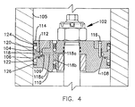
- Piston 102 shown in FIGURE 4 is similar to piston 50 with the exception that seals 68 and 70 used on piston 50 have been combined into a single structure seal 104 forming the dual purpose of sealing against the interior of bore 105.
- Seal 104 includes body 106 having inner skirt 108 which is clamped between shoulder 109 on piston body 110 by projection 112 on ring 114. Cap screws 116 secure ring 114 to piston body 110.
- Seal body 106 includes radial port 118 which communicates from valved passages 118a, 118b and 118c in body 110 to the exterior of seal body 106 between upper arch 120 and lower arch 122.
- Upper arch 120 extends between the outer portion of skirt 108 to upper flange 124 and lower arch 122 extends between the outer portion of skirt 108 and lower flange 126.
- Arches 120 and 122 are the flexible tapering arches such as described with respect to seal 22 and seals 68 and 70.
- Annulus sealing means 130 shown in FIGURES 5, 6, 7, and 8 is positioned in annulus 132 between the interior of a wellhead 134 and the exterior of upstanding rim 136 on seal body 138 which is landed on tubing hanger 140 or other well device, such as a casing hanger.
- Annulus sealing means includes seal ring 142, setting ring 144 and setting sleeve 146.
- the interior surface of setting sleeve 146 includes annular recesses 148 and 150 to coact with snap ring 152 to lock setting sleeve 146 against upward movement after snap ring 152 has been received within upper recess 148. This locks setting sleeve 146, seal ring 142 and setting ring 144 in their set positions.
- Lower recess 150 secures setting sleeve 146 against movement during the lowering of annulus sealing means into its position within annulus 132.
- Annulus sealing means 130 is illustrated in FIGURE 6A in its unset position before the lowering of setting sleeve 146.
- setting rim 154 which extends above setting ring 144 is positioned between inner and outer flanges 156 and 158 of seal ring 142.
- the upper end of setting rim 154 has both inner and outer tapers as shown so that when it is moved into the space between flanges 156 and 158 it wedges them outwardly to cause flexible inner and outer arches 160 and 162 to be deformed against the inner and outer surfaces of annulus 132.
- seal ring 142 includes upper ring body 164 having inner flexible arch 160 extending to inner flange 156 and outer flexible arch 162 extending to outer flange 158.
- Both arches 160 and 162 are similar to the sealing arches previously described and have a reduced thickness of section approaching their central thinnest sealing sections.
- Inner arch 160 has its convex side or sealing surfaces facing inwardly to engage the exterior surface of rim 136 and outer arch 162 has its convex side or sealing surface facing outwardly to engage the interior surface of wellhead 134.
- the sealing position of seal ring 142 is illustrated in FIGURE 6B.
- annulus sealing means 130 is illustrated in FIGURE 7 as annulus sealing means 166 which is similar to sealing means 130 except that it includes a pair of seal rings 168 and 170 and a pair of setting rings 172 and 174 which are positioned to have rims 176 and 178 of setting rings 172 and 174 positioned in the openings between inner and outer flanges 180 and 182 of each of seal rings 168 and 170.
- setting sleeve 184 is forced downwardly, it forces rims 176 and 178 to wedge the outer flanges of each seal ring 168 and 170 apart to bring flexible arches 186 and 188 into sealing engagement with their respective sealing surfaces on the opposite surfaces of the annulus.
- sealing means 166 One additional element used with sealing means 166 is ring 190 which is positioned between sealing rings 168 and 170 as shown.
- Each of flexible sealing arches 184 and 186 is shaped and functions in the manner previously described with respect to seal ring arches 160 and 162, 120 and 122, 82 and 42.
- Seal ring 192 shown in FIGURES 8A and 8B is positioned in annulus 194 between surface 196 of member 198 and surface 200 of member 202.
- Body 204 of ring 192 is supported against shoulder 206 on member 198 and flexible arch 208 extends from body 204 to flange 210 and is of the preferred flexible arch shape to taper to its central sealing section.
- Setting ring 212 is provided to coact with seal ring 192 and includes rim 214 which has surface 216 which is tapered as shown.
- Body 204 includes lip portion 218 which is adjacent surface 196 and coacts with tapered surface 216 of setting ring 212 which when actuated engages the tip of lip portion 218 and wedge it toward surface 196.
- setting ring 212 when in set position urges seal ring body 204 against shoulder 206 to assist in providing a sealing engagement with shoulder 206.
- Valve stem seal 222 illustrated in FIGURES 9 and 10 is similar to annular seal 22 shown in FIGURES 1 and 2. It is shown installed on valve 224 in surrounding relationship to valve stem 226 in bonnet 228 and is retained therein by gland ring 230.
- the interior of bonnet 228 includes stepped opening 231 which includes first bore 232 through which valve stem 226 extends, second bore 234, third bore 236 and fourth bore 238 with shoulder 240 formed between third bore 236 and fourth bore 238.
- Stem seal 222 includes body 242 with outwardly extending flange 244 and flexible arch 246 (similar to the structure of the flexible arches previously described) having its convex portion facing inwardly for sealing engagement with valve stem 226 and extending to outer flange 248. Sealing lip 250 is provided on the exterior of body 242 and tapers downwardly and outwardly for sealing against the surface of third bore 236.
- Valve stem seal 222 is suitable for sealing against valve stem 226 when it is a rotating type of stem, i. e., it rotates to cause the valve member 252 to change its position.
- the inner end of gland ring 230 engages the upper end of seal ring body 242 and clamps flange 244 against shoulder 240.
- Port 254 extends through flange 248 to allow pressure to be transmitted from the valve chamber 256 into the exterior of flexible arch 246 so that it urges the central portion of flexible arch 246 into tight sealing engagement with the exterior surface of valve stem 226.
- valve stem seal could be utilized for sealing around the exterior of a valve stem which reciprocates to cause valve movement rather than rotating.
- sealing lip 250 provides the seal against the surface of third bore 236 so that fluids under pressure cannot pass around the exterior or interior of valve stem seal 222.
Landscapes
- Engineering & Computer Science (AREA)
- General Engineering & Computer Science (AREA)
- Mechanical Engineering (AREA)
- Sealing Devices (AREA)
- Acyclic And Carbocyclic Compounds In Medicinal Compositions (AREA)
- Pharmaceuticals Containing Other Organic And Inorganic Compounds (AREA)
- Peptides Or Proteins (AREA)
- Saccharide Compounds (AREA)
- Confectionery (AREA)
- Heating, Cooling, Or Curing Plastics Or The Like In General (AREA)
- Sealing With Elastic Sealing Lips (AREA)
Priority Applications (8)
| Application Number | Priority Date | Filing Date | Title |
|---|---|---|---|
| DE69018807T DE69018807T2 (de) | 1990-02-07 | 1990-02-07 | Ringförmige Dichtung. |
| AT90301264T ATE121515T1 (de) | 1990-02-07 | 1990-02-07 | Ringförmige dichtung. |
| EP90301264A EP0441015B1 (fr) | 1990-02-07 | 1990-02-07 | Joint d'étanchéité annulaire |
| US07/604,608 US5066029A (en) | 1990-02-07 | 1990-10-26 | Annular sealing apparatus |
| CA002029246A CA2029246A1 (fr) | 1990-02-07 | 1990-11-02 | Appareil de scellement pour espace annulaire |
| AU65809/90A AU633993B2 (en) | 1990-02-07 | 1990-11-05 | Annular sealing apparatus |
| JP2313801A JPH03234976A (ja) | 1990-02-07 | 1990-11-19 | 環状シーリング装置 |
| NO91910093A NO910093L (no) | 1990-02-07 | 1991-01-09 | Ringtetningsanordning. |
Applications Claiming Priority (1)
| Application Number | Priority Date | Filing Date | Title |
|---|---|---|---|
| EP90301264A EP0441015B1 (fr) | 1990-02-07 | 1990-02-07 | Joint d'étanchéité annulaire |
Publications (2)
| Publication Number | Publication Date |
|---|---|
| EP0441015A1 true EP0441015A1 (fr) | 1991-08-14 |
| EP0441015B1 EP0441015B1 (fr) | 1995-04-19 |
Family
ID=8205286
Family Applications (1)
| Application Number | Title | Priority Date | Filing Date |
|---|---|---|---|
| EP90301264A Expired - Lifetime EP0441015B1 (fr) | 1990-02-07 | 1990-02-07 | Joint d'étanchéité annulaire |
Country Status (8)
| Country | Link |
|---|---|
| US (1) | US5066029A (fr) |
| EP (1) | EP0441015B1 (fr) |
| JP (1) | JPH03234976A (fr) |
| AT (1) | ATE121515T1 (fr) |
| AU (1) | AU633993B2 (fr) |
| CA (1) | CA2029246A1 (fr) |
| DE (1) | DE69018807T2 (fr) |
| NO (1) | NO910093L (fr) |
Families Citing this family (11)
| Publication number | Priority date | Publication date | Assignee | Title |
|---|---|---|---|---|
| US5247918A (en) * | 1992-09-17 | 1993-09-28 | Siemens Automotive L.P. | Sealing a direct injection fuel injector to a combustion chamber |
| EG22360A (en) * | 1999-11-24 | 2002-12-31 | Shell Int Research | Setting an annular seal |
| US8066474B1 (en) * | 2006-06-16 | 2011-11-29 | Jansen's Aircraft Systems Controls, Inc. | Variable guide vane actuator |
| US8128062B2 (en) * | 2007-04-05 | 2012-03-06 | Parker-Hannifin Corporation | Valve with self-aligning shaft seal |
| DE102008054045A1 (de) * | 2008-10-30 | 2010-05-06 | Lenze Drives Gmbh | Dichtungsanordnung zwischen einer Welle und einem Gehäuseteil |
| US9157293B2 (en) | 2010-05-06 | 2015-10-13 | Cameron International Corporation | Tunable floating seal insert |
| US9316119B2 (en) * | 2011-09-15 | 2016-04-19 | United Technologies Corporation | Turbomachine secondary seal assembly |
| US9086168B1 (en) | 2012-08-28 | 2015-07-21 | Jansen's Aircraft Systems Controls, Inc. | GHe solenoid operated pressure regulator and gas release manifold |
| JP2016008683A (ja) * | 2014-06-25 | 2016-01-18 | 浜名湖電装株式会社 | 流体制御弁装置 |
| US11629783B2 (en) * | 2018-05-30 | 2023-04-18 | Nok Corporation | Seal ring and sealing structure |
| GB2577736A (en) * | 2018-10-05 | 2020-04-08 | Rolls Royce Plc | Electrode holder |
Citations (2)
| Publication number | Priority date | Publication date | Assignee | Title |
|---|---|---|---|---|
| FR822572A (fr) * | 1936-09-11 | 1938-01-04 | Joint métallique d'étanchéité pour pièces cylindriques en mouvement | |
| GB2196706A (en) * | 1986-10-29 | 1988-05-05 | English Electric Co Ltd | Sealing devices |
Family Cites Families (21)
| Publication number | Priority date | Publication date | Assignee | Title |
|---|---|---|---|---|
| GB219670A (fr) * | 1923-07-23 | 1925-10-05 | J. R. Geigy | |
| US2164195A (en) * | 1938-07-22 | 1939-06-27 | Continental Oil Co | Casing tester |
| US2942666A (en) * | 1956-12-27 | 1960-06-28 | Jersey Prod Res Co | Wireline plugging device |
| US3283823A (en) * | 1963-09-05 | 1966-11-08 | Elbert E Warrington | Well close-off means |
| US3279806A (en) * | 1964-02-21 | 1966-10-18 | Goodrich Co B F | Seal assembly |
| GB1024698A (en) * | 1964-03-03 | 1966-03-30 | Dowty Technical Dev Ltd | Fluid seals |
| US3345078A (en) * | 1966-09-19 | 1967-10-03 | Goodrich Co B F | Seal assembly |
| CA969210A (en) * | 1969-07-14 | 1975-06-10 | John E. Rode | Deformable metallic member, especially for a static seal |
| FR2300269A2 (fr) * | 1975-02-04 | 1976-09-03 | Joint Francais | Joint d'etancheite a element metallique creux deformable |
| CA1071257A (fr) * | 1977-01-25 | 1980-02-05 | West And Son (Engineers) Limited | Anneau d'etancheite |
| US4302020A (en) * | 1980-03-07 | 1981-11-24 | United Aircraft Products, Inc. | Actuating sealing joint |
| SU916836A1 (ru) * | 1980-07-18 | 1982-03-30 | Предприятие П/Я Г-4285 | Уплотнительное устройство |
| US4474106A (en) * | 1982-04-05 | 1984-10-02 | The United States Of America As Represented By The Secretary Of The Army | Fluidic self adjusting seal assembly |
| US4513946A (en) * | 1982-07-12 | 1985-04-30 | Rockwell International Corporation | Valve and valve sealing member |
| US4486002A (en) * | 1982-09-24 | 1984-12-04 | Fmc Corporation | Combined metallic and flexible non-metallic pressure seal |
| US4477087A (en) * | 1983-07-20 | 1984-10-16 | Sutter Jr Leroy V | Seal formed out of a hard metal with a plating of soft metals |
| US4528959A (en) * | 1984-01-23 | 1985-07-16 | Deere & Company | Seal for an internal combustion engine |
| GB2163497B (en) * | 1984-08-22 | 1987-09-16 | Terence Peter Nicholson | Ring seals |
| FR2596483B1 (fr) * | 1986-04-01 | 1989-08-25 | Europ Propulsion | Joint statique metallique et assemblage comportant un tel joint |
| US4739997A (en) * | 1986-09-05 | 1988-04-26 | Potlatch Corporation | Pressurized bearing seal assembly |
| US4854600A (en) * | 1987-01-22 | 1989-08-08 | Eg&G Pressure Science, Inc. | Pressure balanced metallic S-seal |
-
1990
- 1990-02-07 AT AT90301264T patent/ATE121515T1/de not_active IP Right Cessation
- 1990-02-07 EP EP90301264A patent/EP0441015B1/fr not_active Expired - Lifetime
- 1990-02-07 DE DE69018807T patent/DE69018807T2/de not_active Expired - Fee Related
- 1990-10-26 US US07/604,608 patent/US5066029A/en not_active Expired - Fee Related
- 1990-11-02 CA CA002029246A patent/CA2029246A1/fr not_active Abandoned
- 1990-11-05 AU AU65809/90A patent/AU633993B2/en not_active Ceased
- 1990-11-19 JP JP2313801A patent/JPH03234976A/ja active Pending
-
1991
- 1991-01-09 NO NO91910093A patent/NO910093L/no unknown
Patent Citations (2)
| Publication number | Priority date | Publication date | Assignee | Title |
|---|---|---|---|---|
| FR822572A (fr) * | 1936-09-11 | 1938-01-04 | Joint métallique d'étanchéité pour pièces cylindriques en mouvement | |
| GB2196706A (en) * | 1986-10-29 | 1988-05-05 | English Electric Co Ltd | Sealing devices |
Also Published As
| Publication number | Publication date |
|---|---|
| AU6580990A (en) | 1991-08-08 |
| ATE121515T1 (de) | 1995-05-15 |
| CA2029246A1 (fr) | 1991-08-08 |
| EP0441015B1 (fr) | 1995-04-19 |
| NO910093D0 (no) | 1991-01-09 |
| DE69018807T2 (de) | 1995-08-17 |
| AU633993B2 (en) | 1993-02-11 |
| DE69018807D1 (de) | 1995-05-24 |
| JPH03234976A (ja) | 1991-10-18 |
| US5066029A (en) | 1991-11-19 |
| NO910093L (no) | 1991-08-08 |
Similar Documents
| Publication | Publication Date | Title |
|---|---|---|
| US5355961A (en) | Metal and elastomer casing hanger seal | |
| US3967679A (en) | Mud saver valve | |
| US5066029A (en) | Annular sealing apparatus | |
| US3965980A (en) | Mud saver valve | |
| US4310139A (en) | Annular blowout preventer | |
| US4264054A (en) | Metal-to-metal seat hub seals | |
| US5086808A (en) | Balanced sleeve control choke | |
| GB2067235A (en) | Wellhead assembly | |
| EP0333943B1 (fr) | Joint d'étanchéité de tige de soupape | |
| US4556224A (en) | Crossover seal assembly | |
| US4460151A (en) | Annular blowout preventer | |
| GB2115454A (en) | Metal-to-metal seal | |
| US5255890A (en) | Ram type blowout preventer | |
| US3982729A (en) | Back-up seal for diaphragm valve | |
| US4493373A (en) | Dynamic seal for well tools | |
| US4272055A (en) | Single double backseat | |
| US4358085A (en) | Keying means for segmented end ring blowout preventer | |
| US4991650A (en) | Wellhead isolation tool | |
| JPS58131294A (ja) | 封鎖装置 | |
| US5732772A (en) | Dual split tubing hanger | |
| US4460150A (en) | Annular blowout preventer | |
| US2437836A (en) | Safety pressure release | |
| US5673919A (en) | Sealing arrangement with elastomeric sleeve and surrounding receptacle supported by separate housing shoulders | |
| JPH03177663A (ja) | 弁およびその改良されたシート・シール | |
| CN114645688B (zh) | 一种用于封隔井下高压地层溢流的随钻封隔器 |
Legal Events
| Date | Code | Title | Description |
|---|---|---|---|
| PUAI | Public reference made under article 153(3) epc to a published international application that has entered the european phase |
Free format text: ORIGINAL CODE: 0009012 |
|
| AK | Designated contracting states |
Kind code of ref document: A1 Designated state(s): AT DE FR GB NL |
|
| 17P | Request for examination filed |
Effective date: 19920122 |
|
| 17Q | First examination report despatched |
Effective date: 19931022 |
|
| GRAA | (expected) grant |
Free format text: ORIGINAL CODE: 0009210 |
|
| AK | Designated contracting states |
Kind code of ref document: B1 Designated state(s): AT DE FR GB NL |
|
| PG25 | Lapsed in a contracting state [announced via postgrant information from national office to epo] |
Ref country code: NL Free format text: LAPSE BECAUSE OF FAILURE TO SUBMIT A TRANSLATION OF THE DESCRIPTION OR TO PAY THE FEE WITHIN THE PRESCRIBED TIME-LIMIT Effective date: 19950419 Ref country code: AT Effective date: 19950419 |
|
| REF | Corresponds to: |
Ref document number: 121515 Country of ref document: AT Date of ref document: 19950515 Kind code of ref document: T |
|
| REF | Corresponds to: |
Ref document number: 69018807 Country of ref document: DE Date of ref document: 19950524 |
|
| ET | Fr: translation filed | ||
| NLV1 | Nl: lapsed or annulled due to failure to fulfill the requirements of art. 29p and 29m of the patents act | ||
| REG | Reference to a national code |
Ref country code: GB Ref legal event code: 732E |
|
| PG25 | Lapsed in a contracting state [announced via postgrant information from national office to epo] |
Ref country code: GB Effective date: 19960207 |
|
| PLBE | No opposition filed within time limit |
Free format text: ORIGINAL CODE: 0009261 |
|
| STAA | Information on the status of an ep patent application or granted ep patent |
Free format text: STATUS: NO OPPOSITION FILED WITHIN TIME LIMIT |
|
| 26N | No opposition filed | ||
| GBPC | Gb: european patent ceased through non-payment of renewal fee |
Effective date: 19960207 |
|
| PG25 | Lapsed in a contracting state [announced via postgrant information from national office to epo] |
Ref country code: FR Effective date: 19961031 |
|
| PG25 | Lapsed in a contracting state [announced via postgrant information from national office to epo] |
Ref country code: DE Effective date: 19961101 |
|
| REG | Reference to a national code |
Ref country code: FR Ref legal event code: ST |