EP0441094A1 - Fuel injection nozzle - Google Patents
Fuel injection nozzle Download PDFInfo
- Publication number
- EP0441094A1 EP0441094A1 EP90630039A EP90630039A EP0441094A1 EP 0441094 A1 EP0441094 A1 EP 0441094A1 EP 90630039 A EP90630039 A EP 90630039A EP 90630039 A EP90630039 A EP 90630039A EP 0441094 A1 EP0441094 A1 EP 0441094A1
- Authority
- EP
- European Patent Office
- Prior art keywords
- valve
- spring
- nozzle
- seat member
- cap
- Prior art date
- Legal status (The legal status is an assumption and is not a legal conclusion. Google has not performed a legal analysis and makes no representation as to the accuracy of the status listed.)
- Withdrawn
Links
Images



Classifications
-
- B—PERFORMING OPERATIONS; TRANSPORTING
- B25—HAND TOOLS; PORTABLE POWER-DRIVEN TOOLS; MANIPULATORS
- B25B—TOOLS OR BENCH DEVICES NOT OTHERWISE PROVIDED FOR, FOR FASTENING, CONNECTING, DISENGAGING, OR HOLDING
- B25B27/00—Hand tools, specially adapted for fitting together or separating parts or objects whether or not involving some deformation, not otherwise provided for
- B25B27/02—Hand tools, specially adapted for fitting together or separating parts or objects whether or not involving some deformation, not otherwise provided for for connecting objects by press fit or detaching same
- B25B27/023—Hand tools, specially adapted for fitting together or separating parts or objects whether or not involving some deformation, not otherwise provided for for connecting objects by press fit or detaching same using screws
-
- F—MECHANICAL ENGINEERING; LIGHTING; HEATING; WEAPONS; BLASTING
- F02—COMBUSTION ENGINES; HOT-GAS OR COMBUSTION-PRODUCT ENGINE PLANTS
- F02M—SUPPLYING COMBUSTION ENGINES IN GENERAL WITH COMBUSTIBLE MIXTURES OR CONSTITUENTS THEREOF
- F02M45/00—Fuel-injection apparatus characterised by having a cyclic delivery of specific time/pressure or time/quantity relationship
- F02M45/02—Fuel-injection apparatus characterised by having a cyclic delivery of specific time/pressure or time/quantity relationship with each cyclic delivery being separated into two or more parts
- F02M45/04—Fuel-injection apparatus characterised by having a cyclic delivery of specific time/pressure or time/quantity relationship with each cyclic delivery being separated into two or more parts with a small initial part, e.g. initial part for partial load and initial and main part for full load
- F02M45/08—Injectors peculiar thereto
- F02M45/083—Having two or more closing springs acting on injection-valve
-
- F—MECHANICAL ENGINEERING; LIGHTING; HEATING; WEAPONS; BLASTING
- F02—COMBUSTION ENGINES; HOT-GAS OR COMBUSTION-PRODUCT ENGINE PLANTS
- F02M—SUPPLYING COMBUSTION ENGINES IN GENERAL WITH COMBUSTIBLE MIXTURES OR CONSTITUENTS THEREOF
- F02M61/00—Fuel-injectors not provided for in groups F02M39/00 - F02M57/00 or F02M67/00
- F02M61/14—Arrangements of injectors with respect to engines; Mounting of injectors
-
- F—MECHANICAL ENGINEERING; LIGHTING; HEATING; WEAPONS; BLASTING
- F02—COMBUSTION ENGINES; HOT-GAS OR COMBUSTION-PRODUCT ENGINE PLANTS
- F02M—SUPPLYING COMBUSTION ENGINES IN GENERAL WITH COMBUSTIBLE MIXTURES OR CONSTITUENTS THEREOF
- F02M61/00—Fuel-injectors not provided for in groups F02M39/00 - F02M57/00 or F02M67/00
- F02M61/16—Details not provided for in, or of interest apart from, the apparatus of groups F02M61/02 - F02M61/14
- F02M61/166—Selection of particular materials
-
- F—MECHANICAL ENGINEERING; LIGHTING; HEATING; WEAPONS; BLASTING
- F02—COMBUSTION ENGINES; HOT-GAS OR COMBUSTION-PRODUCT ENGINE PLANTS
- F02M—SUPPLYING COMBUSTION ENGINES IN GENERAL WITH COMBUSTIBLE MIXTURES OR CONSTITUENTS THEREOF
- F02M61/00—Fuel-injectors not provided for in groups F02M39/00 - F02M57/00 or F02M67/00
- F02M61/16—Details not provided for in, or of interest apart from, the apparatus of groups F02M61/02 - F02M61/14
- F02M61/168—Assembling; Disassembling; Manufacturing; Adjusting
Definitions
- the present invention relates to a fuel injection nozzle of the type having a plunger or valve which is lifted from its seat by the pressure of fuel delivered to the injector by an associated high pressure pump in measured charges in timed relation with the associated engine.
- U.S. Patent No. 4,790,055 discloses an arrangement in which all the internal components of the nozzle body and the nozzle cap portion are press fit together end-to-end such that assembly can be accomplished serially starting at one end of the nozzle body, solely with linear insertion of the components.
- intricate assembly operations such as rotation, and radial manipulation of parts relative to the nozzle axis are substantially eliminated.
- the internal components that determine the valve opening pressure and the valve lift limit are designed to fit together so that only one component needs to be ground during assembly to assure that essentially all tolerances are eliminated.
- no sealants or adhesives are used internal to the nozzle.
- the nozzle provide two stages of fuel injection, i.e., a first stage in which the valve is lifted from the seat a first distance, against a first valve opening pressure, and a second stage in which the valve is lifted to a total lift stop position, against a higher, second valve opening pressure.
- a two stage spring subassembly can be provided for a nozzle body and inlet arrangement of the type generally described in United States Patent 4,790,055, with only a modest reduction in the degree of automation achievable relative to the single stage embodiment of the invention.
- the two stage embodiment of the present invention permits independent adjustment of lift and valve opening pressure, during both manufacturing and refurbishing of the nozzle.
- the two stage nozzle contains first and second spring seat members in the upper portion of the cap, and third and fourth spring seat members in the lower portion of the cap.
- the uppermost of the first and second spring seat members is adapted to close the upper end of the nozzle cap, provide an axially adjustable seat cooperating with the second seat member to hold the coil spring that establishes the first stage valve opening pressure, and support an axially adjustable stem which establishes the valve total lift limit.
- the third and fourth valve seat members cooperate to establish the second stage valve opening pressure, which is adjustable by the axial positioning of the third seat member.
- the lowermost, fourth seat is adjustably spaced by an annular shim, above a shoulder on the valve member, thereby providing adjustability for the first stage lift distance.
- the adjustable spring seat members preferably are threaded to the internal bore of the nozzle cap, so that all parts fit together serially and are readily accessible for adjustment and testing as the nozzle cap internals are assembled.
- FIGS 1, 2 and 3 show a fuel injection nozzle 10 of the type disclosed in U.S. Patent 4,790,055, in which the exterior components are a nozzle body 12, a nozzle cap 14, a fuel inlet stud 16, and a leak-off cap 18.
- fuel is supplied through passages 20,22 in the fuel inlet stud, to a valve chamber 24 in the upper portion of the nozzle body.
- An elongated nozzle valve 26 is axially reciprocable within the nozzle body 12 and includes a conical nose 28 at its lower end for sealing against a tip seat 30 and intermittently providing flow through discharge apertures 32 in the nozzle tip 34.
- the valve 26 is reciprocated as a result of the intermittent fuel pulses entering the valve chamber 24, which apply hydraulic pressure on the actuating surface 36 of the valve. This pressure working on the differential area of the valve in turn lifts the valve nose portion 28 off the tip seat 30, exposing the discharge apertures 32 to the high pressure fuel occupying the space in the axial channel 38 of the nozzle body 12, traversed by the valve 26.
- the spring subassembly 40 in the nozzle cap 14 includes a central lift stop 42, a coil compression spring 44 and spring seats 46, 48 arranged for biasing the valve downwardly to close the valve and establish a minimum opening pressure. Fluid at low pressure exits the nozzle cap 14 through a channel 50 leading to channels 52, 54 in the hydraulic connections 56 of the leak-off cap 18.
- a variety of interchangeable leak-off caps can be utilized, depending on customer needs.
- the nozzle body 12 has a substantially constant outer diameter except for an inwardly tapered shoulder 60 at the lower end thereof.
- a nozzle tip insert 34 is press fit and preferably stoked into a cavity 62 formed at the lower extremity of the nozzle body, the tip including the valve seat 30 and the discharge apertures 32.
- a combustion hem seal 64 Located above the tip cavity 62 on the exterior of the nozzle body, is a combustion hem seal 64, and further up the nozzle body immediately below the connection of the nozzle body to the fuel inlet stud is a hem seal 66.
- Hem 66 is a dust/water seal that reduces vibration, stabilizes the nozzle and establishes the nozzle axial location relative to the cylinder head.
- the nozzle 70 of the nozzle assembly embodiment 72 illustrated in Figure 2 is substantially similar to that illustrated in Figure 1 except that the nozzle body 74 is adapted to incorporate the so-called "slim tip" insert 76.
- the nozzle assembly 72 illustrated in Figure 2 includes the associated clamping subassembly 78 for securing the nozzle 70 to the cylinder head 80.
- the primary seal 82 between the nozzle 70 and the cylinder head 80 is effected in the mounting socket 84, at the transition shoulder 86 of nozzle body 74 to the nozzle tip insert 76.
- the inwardly tapered shoulder 86 on the nozzle body mates with an opposing tapered shoulder 88 on the cylinder head mounting socket 84, with a relatively thin, frustoconical seal member 82 interposed therebetween.
- the clamp subassembly 78 urges the nozzle 70 downward into the cylinder mounting socket 84 such that the major component of the vertical sealing pressure is applied against the combustion seal 82.
- the head seal 90 at the upper surface 92 of the cylinder head is secondary in nature, and is intended primarily to prevent dust/water ingress into annular passageway between the nozzle body and eye head jacket to reduce vibrations and stabilize the nozzle. Seal 82 and shoulder 88 also establishes nozzle axial location relative to the cylinder head.
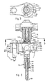
- Figures 4-8 illustrate a first embodiment of the nozzle having a spring subassembly which provides two stages of valve opening. Items in Figures 4-8 that carry the same numeric identifier as appear in Figures 1-3, represent identical or substantial equivalent structural components.
- the nozzle body subassembly which has been preassembled and tested, includes the nozzle body 12, inlet stud 16, and a two step valve 280.
- the valve 280 passes through the axial channel 38, and has an actuating surface 36 disposed in the valve chamber 24.
- a nozzle tip 34, cavity 62, seat 30, and discharge apertures 32, as shown, for example in Figure 1, are also present.
- a guide member 144 is preferably staked to the counterbore 154 near the upper end of the valve body 12.
- the upper portion of the valve 280 includes an enlarged bearing surface 160 for axially sliding within guide member 144 and an annular shoulder 282 from which a valve stem 284 projects axially upward.
- the shoulder 282 and stem 284 are located above the upper end 140 of the valve body when the nozzle is seated.
- a two stage cap barrel 286 and a cap lower fitting 288 are pre-threaded together and the lower fitting 288 is then screwed at 290 to the nozzle body 12, immediately above the inlet stud ring portion 132.
- the cap lower fitting 288 preferably includes a flange portion 172 which engages the stud ring 132, and, at its upper end, an inwardly extending annular ledge 292.
- a first stage lift shim 294 typically in the form of an annular washer, is axially passed downwardly through the barrel 286 until it is supported against further downward movement by the annular ledge 292.
- the ledge 292 and shim 294 have central openings large enough for the valve shoulder 282 and bearing surface 160 to pass.
- the height, or axial extent, of the shim 294 is selected such that when the valve is seated, a predetermined first stage lift distance L1 is defined between the shoulder 282 and the upper surface of the shim 294.
- the nozzle spring arrangement is further assembled as shown in Figure 6, by passing the second stage lower seat member 296 axially through the barrel 286, until the lower portion of the seat member 296 is axially supported by the shim 294 and the valve stem 284 projects upwardly through a bore 298 in the seat member 296.
- One end of a coil spring 300 is then placed on the spring seat 296 and the second stage upper seat member 302, which is externally threaded, is advanced along the barrel internal threads 304 until the desired spring preload is achieved.
- a threaded locknut 306 is then advanced through the barrel to lock the seat member 302 in place.
- the distance between the seating surfaces of the second stage lower seat member 296 and the second stage upper seat member 302, defines the preloaded coil spring length 308, and establishes the second stage valve opening pressure.
- the second stage upper seat 302 and the locknut 306 are generally annular, so that a push rod 310 can be axially passed therethrough into axially aligned rigid contact with the valve stem 284, as shown in Figure 7.
- the upper end of the push rod 310 projects above the second stage upper seat member 302 into a pocket 303 defined by the inner wall of the locknut 306 and the upper surface of seat member 302.
- the first stage lower seat member 312, which is similar to valve seat member 296, has a base portion and upwardly projecting pedestal. It is lowered into the pocket 303, for resting on the push rod 310.
- the first stage coil spring 314 is then seated on the first stage lower seat 312.
- the first stage upper seat member 316 is preassembled with stem 318 passing centrally therethrough.
- the stem 318 includes a threaded head portion 320 which engages internal threads in the center of first stage upper seat member 316.
- the first stage spring 314 enters the inverted cup-like portion of the first stage upper seat 316 and the externally threaded portion of the seat member 316 is secured to the threaded bore 304 of the barrel.
- the first stage upper seat member 316 is adjusted axially to define the preloaded spring length 324, which in turn defines the first stage valve opening pressure.
- the head 320 is independently adjusted, to define the second stage total lift distance L2, and locknut 322 secures the head 320 in place.
- a leak-off ring 328 is slid over the upper end of the cap barrel and the lock bonnet 326 is advanced along the exposed periphery of the first stage upper seat member 316, thereby locking the seat member 316 in place.
- this embodiment of the invention includes a generally cylindrical nozzle cap 286 having a partially threaded inner wall 304 and closed upper end 316, the nozzle cap including means 290 for rigidly securing the cap to the upper end of the nozzle body 12 above the connection of the inlet stud 132 to the nozzle body.
- a spring subassembly is mounted within the nozzle cap along the nozzle body axis and includes a first nozzle seat 312 in rigid alignment with the upper end 284 of the valve for displacement therewith axially within the cap.
- rigid alignment means the capability to rigidly transmit linear force.
- a second spring seat 316 is supported by the cap against axial movement relative to the cap.
- a first spring 314 is interposed and supported between the first and second spring seats 312, 316.
- a rigid stem 318 extends axially from one of the first and second spring seats 312, 316 and a rigid pedestal or the like extends axially from the other of the first and second spring seats, toward each other, the stem and pedestal having opposed free ends 330 which define an axial gap, L2,.
- the first spring 314 acts through the first spring seat 312 to provide a downward bias on the valve 280 against the seat 30 in the tip 28, and the stem and pedestal 318, 312 interact to provide a stop to limit the total lift L2 of the valve upwardly from the valve seat.
- a third spring seat 302 is situated below the first spring seat 312 and is supported by the cap against axial movement relative to the cap.
- a fourth spring seat 296 is situated below the third spring seat 302 and is supported against downward movement by the cap, or its equivalent such as fitting 288, in axially spaced alignment above the valve shoulder 282.
- a push rod 310 is axially slidable through the third seat member 302 and the valve stem 284 is axially slidable through the fourth seat member 296.
- a second spring 300 is interposed between the third and fourth seats 302, 296, with the valve stem 284 and push rod 310 in rigid axial alignment throughout the linear extent of the spring 300.
- the lift distance and valve opening pressure for both the first and second stages are adjustable.
- the first stage lift distance is adjusted by the selection of the axial height of shim 294, whereas the first stage valve opening pressure is adjusted by means of the threaded second seat 316.
- the second stage total lift distance is adjusted by means of the threaded head 320 on stem 318 and the second stage valve opening pressure is adjusted by means of the threaded third seat member 302.
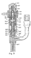
- Figure 9 shows another embodiment of the two stage spring subassembly, in which components or parts having substantially identical shape and function as those shown in Figures 1-9, carry the same reference numeral, and parts or components which are structurally different but perform a similar function to previously described parts, are identified by the same reference numeral primed (').
- the most evident difference between the spring subassemblies of Figures 9 and 8, are with respect to the interaction of the fourth spring seat with the upper end of the valve.
- the valve 280' has the same shape as the valve shown in Figures 1-3, including a flat upper end 18.
- the enhanced push rod member 332 of Figure 9 has a rod-like upper portion 310' and an enlarged lower portion 284' which functions as a valve extension member, equivalent to the stem 284 shown in Figure 4.
- the valve extension portion 284' includes an upwardly facing, annular shoulder 282' which is initially spaced below the spring seat 296', and a downwardly facing pocket 336 which the valve upper end 18 seats at 334.
- valve 280' does not require the machining of a stem portion such as 284 in Figure 4, but the enhanced push rod member 332 requires a machining of the valve extension portion 284'.
- FIG. 9 A significant advantage to the embodiment shown in Figure 9, is the relatively larger contact areas between shoulder 282' and seat 296', as compared with the contact areas 282, 296, and a relatively stiffer valve extension portion 284' as compared with the valve stem 284.
- valve seat 312 could in some circumstances be integral with the enhanced push rod member 332.
Landscapes
- Engineering & Computer Science (AREA)
- Mechanical Engineering (AREA)
- Chemical & Material Sciences (AREA)
- Combustion & Propulsion (AREA)
- General Engineering & Computer Science (AREA)
- Manufacturing & Machinery (AREA)
- Fuel-Injection Apparatus (AREA)
Abstract
A spring subassembly mounted within the nozzle cap along the nozzle body axis, includes, a first spring seat member (312) in rigid axial alignment with the upper end of the valve member for displacement therewith axially within the cap, the rigid alignment including a push rod (310') rigidly extending between and in contact with the first spring seat member and the valve member. A second spring seat member (316) is supported by the cap above the first spring seat member (312) against upward axial movement relative to the nozzle cap. A first coil spring (314) is interposed and supported between the first and second spring seat members (312 and 316), and a rigid stem (318) extends axially from one of the first and second spring seat members (312, 316) and a rigid pedestal extends axially from the other of the first and second spring seat members toward each other. The stem and pedestal have opposed free ends defining an axial gap (L₂) therebetween. The first spring acts through the first spring seat member to provide an opening pressure bias on the valve member nose against the nozzle tip seat, and the stem and pedestal interacting to provide a stop limit to the total lift of the valve member nose upwardly from the nozzle tip seat. The valve member (280') also includes a valve stem (284') projecting axially from an annular valve shoulder (282'), so that the stem contacts the push rod (310'). The spring subassembly further includes, a third spring seat member (302) situated below the first spring seat member (312) and supported by the cap against axial movement, a fourth spring seat member (296') situated below the third spring seat member (302) and supported by the cap in axially spaced alignment above the valve shoulder (282'). The push rod is axially slidable through the third valve seat member (302) and the valve stem is axially slidable through the fourth valve seat member (296'). A second coil spring (300) is interposed and supported between the third and fourth spring seat members (302, 296'), such that the second spring resists upward movement of the valve member with a second pressure after the opening pressure bias is overcome and the valve shoulder (282') contacts the fourth valve seat member (296').
Description
- The present invention relates to a fuel injection nozzle of the type having a plunger or valve which is lifted from its seat by the pressure of fuel delivered to the injector by an associated high pressure pump in measured charges in timed relation with the associated engine.
- Representative fuel injector assemblies are described in the following United States patents:

- The improvements in fuel injection nozzles chronicled by the succession of patents identified above, include so called "two-stage" nozzles. In the present competitive market for these types of devices, the need has arisen to significantly reduce the cost of materials and fabrication without compromising performance. The devices represented by the prior art require considerable labor input, particularly in the machining of the parts and the care required in assembly and the adjustability of the two stages.
- U.S. Patent No. 4,790,055 discloses an arrangement in which all the internal components of the nozzle body and the nozzle cap portion are press fit together end-to-end such that assembly can be accomplished serially starting at one end of the nozzle body, solely with linear insertion of the components. Thus, intricate assembly operations such as rotation, and radial manipulation of parts relative to the nozzle axis are substantially eliminated. This permits automated assembly with a significant savings in cost. Furthermore, the internal components that determine the valve opening pressure and the valve lift limit are designed to fit together so that only one component needs to be ground during assembly to assure that essentially all tolerances are eliminated. Preferably, no sealants or adhesives are used internal to the nozzle. Under some situations, it is preferred that the nozzle provide two stages of fuel injection, i.e., a first stage in which the valve is lifted from the seat a first distance, against a first valve opening pressure, and a second stage in which the valve is lifted to a total lift stop position, against a higher, second valve opening pressure.
- Accordingly, it is an object of the present invention to provide a two-stage fuel injection nozzle assembly in which the component parts are simply fabricated, easily assembled by automated processes, and easily adjusted without compromising the performance of the nozzles.
- In accordance with the invention, a two stage spring subassembly can be provided for a nozzle body and inlet arrangement of the type generally described in United States Patent 4,790,055, with only a modest reduction in the degree of automation achievable relative to the single stage embodiment of the invention. Moreover, the two stage embodiment of the present invention permits independent adjustment of lift and valve opening pressure, during both manufacturing and refurbishing of the nozzle.
- Preferably, the two stage nozzle contains first and second spring seat members in the upper portion of the cap, and third and fourth spring seat members in the lower portion of the cap. The uppermost of the first and second spring seat members is adapted to close the upper end of the nozzle cap, provide an axially adjustable seat cooperating with the second seat member to hold the coil spring that establishes the first stage valve opening pressure, and support an axially adjustable stem which establishes the valve total lift limit. The third and fourth valve seat members cooperate to establish the second stage valve opening pressure, which is adjustable by the axial positioning of the third seat member. The lowermost, fourth seat, is adjustably spaced by an annular shim, above a shoulder on the valve member, thereby providing adjustability for the first stage lift distance.
- Although this embodiment of the invention requires adjustment of the seat members and use of a shim during assembly, premeasurement and grinding of the spring assembly components is avoided. The adjustable spring seat members preferably are threaded to the internal bore of the nozzle cap, so that all parts fit together serially and are readily accessible for adjustment and testing as the nozzle cap internals are assembled.
- These and other features and advantages of the invention will be evident to those skilled in this art from the following description of the preferred embodiments and accompanying figures, in which:
- Figure 1 is an elevation view, partly in section, of a known single stage fuel injection nozzle;
- Figure 2 is an elevation view of a known fuel injection nozzle having a slim tip profile;
- Figure 3 is a top view of the nozzle assembly shown in Figure 2;
- Figure 4 is an elevation view, partly in section, of the upper portion of the nozzle body, with inlet stud attached, preassembled and tested and ready for attachment of the nozzle cap and associated two stage spring subassembly in accordance with the invention;
- Figure 5 is a view similar to Figure 4, showing the first stage of the assembly of the nozzle cap;
- Figure 6 is a view similar to Figure 5, showing a subsequent stage of assembly of the nozzle cap;
- Figure 7 is a view similar to Figure 6, showing a further stage of the assembly of the nozzle cap;
- Figure 8 is a view similar to Figure 7, showing the last step for assembling the nozzle cap, just prior to adding the leak-off ring and bonnet to complete the nozzle; and
- Figure 9 shows another embodiment of a two stage spring subassembly.
- Figures 1, 2 and 3 show a
fuel injection nozzle 10 of the type disclosed in U.S. Patent 4,790,055, in which the exterior components are anozzle body 12, anozzle cap 14, afuel inlet stud 16, and a leak-off cap 18. During operation, fuel is supplied throughpassages valve chamber 24 in the upper portion of the nozzle body. Anelongated nozzle valve 26 is axially reciprocable within thenozzle body 12 and includes aconical nose 28 at its lower end for sealing against atip seat 30 and intermittently providing flow throughdischarge apertures 32 in thenozzle tip 34. Thevalve 26 is reciprocated as a result of the intermittent fuel pulses entering thevalve chamber 24, which apply hydraulic pressure on the actuatingsurface 36 of the valve. This pressure working on the differential area of the valve in turn lifts thevalve nose portion 28 off thetip seat 30, exposing thedischarge apertures 32 to the high pressure fuel occupying the space in theaxial channel 38 of thenozzle body 12, traversed by thevalve 26. Thespring subassembly 40 in thenozzle cap 14 includes acentral lift stop 42, a coil compression spring 44 andspring seats nozzle cap 14 through achannel 50 leading tochannels hydraulic connections 56 of the leak-off cap 18. A variety of interchangeable leak-off caps can be utilized, depending on customer needs. - In the embodiment illustrated in Figure 1, the
nozzle body 12 has a substantially constant outer diameter except for an inwardlytapered shoulder 60 at the lower end thereof. Anozzle tip insert 34 is press fit and preferably stoked into acavity 62 formed at the lower extremity of the nozzle body, the tip including thevalve seat 30 and thedischarge apertures 32. Immediately above thetip cavity 62 on the exterior of the nozzle body, is a combustion hem seal 64, and further up the nozzle body immediately below the connection of the nozzle body to the fuel inlet stud is ahem seal 66.Hem 66 is a dust/water seal that reduces vibration, stabilizes the nozzle and establishes the nozzle axial location relative to the cylinder head. - The
nozzle 70 of thenozzle assembly embodiment 72 illustrated in Figure 2 is substantially similar to that illustrated in Figure 1 except that thenozzle body 74 is adapted to incorporate the so-called "slim tip"insert 76. Thenozzle assembly 72 illustrated in Figure 2 includes the associatedclamping subassembly 78 for securing thenozzle 70 to thecylinder head 80. In this embodiment, theprimary seal 82 between thenozzle 70 and thecylinder head 80 is effected in themounting socket 84, at thetransition shoulder 86 ofnozzle body 74 to thenozzle tip insert 76. The inwardlytapered shoulder 86 on the nozzle body mates with an opposingtapered shoulder 88 on the cylinderhead mounting socket 84, with a relatively thin,frustoconical seal member 82 interposed therebetween. The clamp subassembly 78 urges thenozzle 70 downward into thecylinder mounting socket 84 such that the major component of the vertical sealing pressure is applied against thecombustion seal 82. Thehead seal 90 at theupper surface 92 of the cylinder head is secondary in nature, and is intended primarily to prevent dust/water ingress into annular passageway between the nozzle body and eye head jacket to reduce vibrations and stabilize the nozzle.Seal 82 andshoulder 88 also establishes nozzle axial location relative to the cylinder head. - Figures 4-8 illustrate a first embodiment of the nozzle having a spring subassembly which provides two stages of valve opening. Items in Figures 4-8 that carry the same numeric identifier as appear in Figures 1-3, represent identical or substantial equivalent structural components.
- In Figure 4, the nozzle body subassembly, which has been preassembled and tested, includes the
nozzle body 12,inlet stud 16, and a twostep valve 280. Thevalve 280 passes through theaxial channel 38, and has an actuatingsurface 36 disposed in thevalve chamber 24. Anozzle tip 34,cavity 62,seat 30, anddischarge apertures 32, as shown, for example in Figure 1, are also present. At the upper portion ofnozzle body 12, aguide member 144 is preferably staked to thecounterbore 154 near the upper end of thevalve body 12. The upper portion of thevalve 280 includes an enlargedbearing surface 160 for axially sliding withinguide member 144 and anannular shoulder 282 from which avalve stem 284 projects axially upward. Theshoulder 282 andstem 284 are located above theupper end 140 of the valve body when the nozzle is seated. - As shown in Figure 5, a two
stage cap barrel 286 and a caplower fitting 288 are pre-threaded together and thelower fitting 288 is then screwed at 290 to thenozzle body 12, immediately above the inletstud ring portion 132. The caplower fitting 288 preferably includes aflange portion 172 which engages thestud ring 132, and, at its upper end, an inwardly extendingannular ledge 292. After thelower fitting 288 has been secured to thenozzle body 12, a firststage lift shim 294, typically in the form of an annular washer, is axially passed downwardly through thebarrel 286 until it is supported against further downward movement by theannular ledge 292. Theledge 292 andshim 294 have central openings large enough for thevalve shoulder 282 and bearingsurface 160 to pass. The height, or axial extent, of theshim 294 is selected such that when the valve is seated, a predetermined first stage lift distance L₁ is defined between theshoulder 282 and the upper surface of theshim 294. - The nozzle spring arrangement is further assembled as shown in Figure 6, by passing the second stage
lower seat member 296 axially through thebarrel 286, until the lower portion of theseat member 296 is axially supported by theshim 294 and the valve stem 284 projects upwardly through abore 298 in theseat member 296. One end of acoil spring 300 is then placed on thespring seat 296 and the second stageupper seat member 302, which is externally threaded, is advanced along the barrelinternal threads 304 until the desired spring preload is achieved. A threadedlocknut 306 is then advanced through the barrel to lock theseat member 302 in place. The distance between the seating surfaces of the second stagelower seat member 296 and the second stageupper seat member 302, defines the preloadedcoil spring length 308, and establishes the second stage valve opening pressure. - The second stage
upper seat 302 and thelocknut 306 are generally annular, so that apush rod 310 can be axially passed therethrough into axially aligned rigid contact with thevalve stem 284, as shown in Figure 7. The upper end of thepush rod 310 projects above the second stageupper seat member 302 into apocket 303 defined by the inner wall of thelocknut 306 and the upper surface ofseat member 302. The first stagelower seat member 312, which is similar tovalve seat member 296, has a base portion and upwardly projecting pedestal. It is lowered into thepocket 303, for resting on thepush rod 310. The firststage coil spring 314 is then seated on the first stagelower seat 312. The first stageupper seat member 316 is preassembled withstem 318 passing centrally therethrough. Thestem 318 includes a threadedhead portion 320 which engages internal threads in the center of first stageupper seat member 316. Thefirst stage spring 314 enters the inverted cup-like portion of the first stageupper seat 316 and the externally threaded portion of theseat member 316 is secured to the threaded bore 304 of the barrel. - As shown in Figure 8, the first stage
upper seat member 316 is adjusted axially to define thepreloaded spring length 324, which in turn defines the first stage valve opening pressure. Thehead 320 is independently adjusted, to define the second stage total lift distance L₂, andlocknut 322 secures thehead 320 in place. A leak-off ring 328 is slid over the upper end of the cap barrel and thelock bonnet 326 is advanced along the exposed periphery of the first stageupper seat member 316, thereby locking theseat member 316 in place. - Thus, as illustrated in Figure 8, this embodiment of the invention includes a generally
cylindrical nozzle cap 286 having a partially threadedinner wall 304 and closedupper end 316, the nozzle cap including means 290 for rigidly securing the cap to the upper end of thenozzle body 12 above the connection of theinlet stud 132 to the nozzle body. A spring subassembly is mounted within the nozzle cap along the nozzle body axis and includes afirst nozzle seat 312 in rigid alignment with theupper end 284 of the valve for displacement therewith axially within the cap. In this context, rigid alignment means the capability to rigidly transmit linear force. Asecond spring seat 316 is supported by the cap against axial movement relative to the cap. Afirst spring 314 is interposed and supported between the first and second spring seats 312, 316. Arigid stem 318 extends axially from one of the first and second spring seats 312, 316 and a rigid pedestal or the like extends axially from the other of the first and second spring seats, toward each other, the stem and pedestal having opposed free ends 330 which define an axial gap, L₂,. Thefirst spring 314 acts through thefirst spring seat 312 to provide a downward bias on thevalve 280 against theseat 30 in thetip 28, and the stem andpedestal third spring seat 302 is situated below thefirst spring seat 312 and is supported by the cap against axial movement relative to the cap. Afourth spring seat 296 is situated below thethird spring seat 302 and is supported against downward movement by the cap, or its equivalent such asfitting 288, in axially spaced alignment above thevalve shoulder 282. Apush rod 310 is axially slidable through thethird seat member 302 and thevalve stem 284 is axially slidable through thefourth seat member 296. Asecond spring 300 is interposed between the third andfourth seats valve stem 284 and pushrod 310 in rigid axial alignment throughout the linear extent of thespring 300. - The lift distance and valve opening pressure for both the first and second stages are adjustable. The first stage lift distance is adjusted by the selection of the axial height of
shim 294, whereas the first stage valve opening pressure is adjusted by means of the threadedsecond seat 316. The second stage total lift distance is adjusted by means of the threadedhead 320 onstem 318 and the second stage valve opening pressure is adjusted by means of the threadedthird seat member 302. - Figure 9 shows another embodiment of the two stage spring subassembly, in which components or parts having substantially identical shape and function as those shown in Figures 1-9, carry the same reference numeral, and parts or components which are structurally different but perform a similar function to previously described parts, are identified by the same reference numeral primed ('). The most evident difference between the spring subassemblies of Figures 9 and 8, are with respect to the interaction of the fourth spring seat with the upper end of the valve. In the embodiment of Figure 9, the valve 280' has the same shape as the valve shown in Figures 1-3, including a flat
upper end 18. Whereas in the embodiment of Figure 8push rod 310 was, in essence, a rod segment tapered at both ends, the enhancedpush rod member 332 of Figure 9 has a rod-like upper portion 310' and an enlarged lower portion 284' which functions as a valve extension member, equivalent to thestem 284 shown in Figure 4. The valve extension portion 284' includes an upwardly facing, annular shoulder 282' which is initially spaced below the spring seat 296', and a downwardly facingpocket 336 which the valveupper end 18 seats at 334. - In this embodiment, the valve 280' does not require the machining of a stem portion such as 284 in Figure 4, but the enhanced
push rod member 332 requires a machining of the valve extension portion 284'. - It should be appreciated that functionally, the embodiments of Figure 8 and Figure 9 are essentially identical. A significant advantage to the embodiment shown in Figure 9, is the relatively larger contact areas between shoulder 282' and seat 296', as compared with the
contact areas valve stem 284. - It should also be appreciated that variations can be made without departing from the essential features of the two stage subassembly as shown. For example, the
valve seat 312 could in some circumstances be integral with the enhancedpush rod member 332. The surface of theseat 312 which faces the surface of thefree end 330 ofstem 318, need not axially extend from the spring seating surface of theseat 312.
Claims (3)
- A fuel injection nozzle comprising an elongated, generally cylindrical nozzle body having a nozzle tip and a nozzle seat at the lower end of the body, a central bore extending from the nozzle seat axially along the body, and a valve chamber having a larger diameter than the central bore located at the upper end of the body; a single elongated valve member disposed axially within the nozzle body, said valve member having a nose portion for engaging the nozzle seat, a stem portion extending from the nose portion to the valve chamber, a valve actuation portion in the valve chamber, and an upper end portion extending upwardly from the valve actuation portion to a position above the upper end of the nozzle body; an inlet stud rigidly connected to the exterior of the valve body adjacent the valve chamber; a fuel inlet passage extending through the inlet stud and nozzle body to the valve chamber, for delivering fuel in measured Pulses to the valve actuation portion, whereby the valve is lifted from the nozzle tip seat and the fuel is discharged from the nozzle tip; a substantially cylindrical nozzle cap having a closed upper end, said nozzle cap including means for rigidly securing the cap to the upper end of the nozzle body above the connection of the inlet stud to the nozzle body; a spring subassembly mounted within the nozzle cap along the nozzle body axis, including, a first spring seat member (46, 312) in rigid axial alignment with the upper end of the valve member for displacement therewith axially within the cap, the rigid alignment including a push rod (310) rigidly extending between and in contact with the first spring seat member and the valve member, a second spring seat member (48, 316) supported by the cap above the first spring seat member (46, 312) against upward axial movement relative to the nozzle cap, a first coil spring (44, 314) interposed and supported between the first and second spring seat members (46, 312 and 48, 316), and a rigid stem (40, 318) extending axially from one of said first and second spring seat members (312, 316) and a rigid pedestal extending axially from the other of said first and second spring seat members toward each other, the stem and pedestal having opposed free ends defining an axial gap (F, L₂) therebetween, said first spring acting through said first spring seat member to provide the sole nozzle opening pressure bias on the valve member nose against the nozzle tip seat, and said stem and pedestal interacting to provide a stop limit to the total lift of the valve member nose upwardly from the nozzle tip seat, characterized in that:
said valve member (280) has associated therewith a valve stem (284) projecting axially from an annular valve shoulder (282), said valve stem contacting said push rod (310) and
the spring subassembly further includes,
a third spring seat member (302) situated below the first spring seat member (312) and supported by the cap against axial movement,
a fourth spring seat member (296) situated below the third spring seat member (302) and supported by the cap in axially spaced alignment above the valve shoulder (282), said push rod being axially movable through the third valve seat member (302) and said valve stem being axially movable through said fourth valve seat member (296), and
a second coil spring (300) interposed and supported between said third and fourth spring seat members (302, 296), such that said second spring resists upward movement of said valve member with a second pressure after said opening pressure bias is overcome and the valve shoulder (282) contacts the fourth valve seat member (296). - The nozzle of claim 1 characterized in that:
the second spring seat member (316) includes means engaging the cap for adjusting the axial position of the second spring seat member within the nozzle cap and means for adjusting the axial position of one of the stem (318) and pedestal relative to the second valve seat member to change said axial gap (L₂), and
said third spring seat member (302) includes means engaging the cap for adjusting the axial position of the third spring seat member within the nozzle cap to change said second pressure. - The nozzle of claim 2 characterized in that:
the means for rigidly securing the cap to the upper end of the valve body includes a fitting (288) threadably engaged to the valve body upper end, and
said spring subassembly further includes shim means supported by the fitting transversely to the axis of the cap, said shim axially supporting said fourth seat member (296) in spaced relation from the valve shoulder (282), such that when the upward force on said valve actuating portion exceeds said opening pressure defined by said first spring, said valve shoulder lifts said fourth seat member upwardly against the second pressure defined by said second spring.
Applications Claiming Priority (1)
| Application Number | Priority Date | Filing Date | Title |
|---|---|---|---|
| US07/243,286 US4938193A (en) | 1987-06-15 | 1988-09-09 | Fuel injection nozzle |
Publications (1)
| Publication Number | Publication Date |
|---|---|
| EP0441094A1 true EP0441094A1 (en) | 1991-08-14 |
Family
ID=22918132
Family Applications (1)
| Application Number | Title | Priority Date | Filing Date |
|---|---|---|---|
| EP90630039A Withdrawn EP0441094A1 (en) | 1988-09-09 | 1990-02-09 | Fuel injection nozzle |
Country Status (2)
| Country | Link |
|---|---|
| US (1) | US4938193A (en) |
| EP (1) | EP0441094A1 (en) |
Cited By (1)
| Publication number | Priority date | Publication date | Assignee | Title |
|---|---|---|---|---|
| EP0653561A1 (en) * | 1993-11-11 | 1995-05-17 | Lucas Industries Public Limited Company | Fuel injection nozzle |
Families Citing this family (52)
| Publication number | Priority date | Publication date | Assignee | Title |
|---|---|---|---|---|
| US5035221A (en) * | 1989-01-11 | 1991-07-30 | Martin Tiby M | High pressure electronic common-rail fuel injection system for diesel engines |
| US5012786A (en) * | 1990-03-08 | 1991-05-07 | Voss James R | Diesel engine fuel injection system |
| DE4101235C1 (en) * | 1991-01-17 | 1992-06-04 | Robert Bosch Gmbh, 7000 Stuttgart, De | |
| GB9121592D0 (en) * | 1991-10-11 | 1991-11-27 | Ricardo Consulting Eng | Fuel injectors for diesel engines |
| DE4239173C1 (en) * | 1992-11-21 | 1993-09-02 | Mercedes-Benz Aktiengesellschaft, 70327 Stuttgart, De | Cylinder-head for fuel-injection engine - has pressure pipe passing through clamping screw and with union at protruding end for injection pipe |
| US5499612A (en) * | 1994-10-03 | 1996-03-19 | Caterpillar Inc. | Dual-function clamping assembly adapted for a hydraulically-actuated fuel injector |
| US5697345A (en) * | 1994-12-28 | 1997-12-16 | Cummins Engine Company, Inc. | Clamping load distributor for a fuel injector |
| US5706786A (en) * | 1994-12-28 | 1998-01-13 | Cummins Engine Company, Inc. | Distortion reducing load ring for a fuel injector |
| US5566658A (en) * | 1995-04-21 | 1996-10-22 | Cummins Engine Company, Inc. | Clamping load distributor and top stop for a fuel injector |
| GB2311558A (en) * | 1996-03-28 | 1997-10-01 | Stanadyne Automotive Corp | Fuel injection nozzle with compressive radial pre-loading |
| KR100301383B1 (en) * | 1996-07-18 | 2002-07-03 | 오카메 히로무 | Fuel injection device |
| US5785022A (en) * | 1997-05-28 | 1998-07-28 | Epic Technical Group, Inc. | Fuel injector post |
| GB9725805D0 (en) * | 1997-12-06 | 1998-02-04 | Lucas Ind Plc | Fuel injector nozzle |
| DE19753518A1 (en) * | 1997-12-03 | 1999-06-10 | Bosch Gmbh Robert | Fuel supply device |
| US5983864A (en) * | 1997-12-23 | 1999-11-16 | Caterpillar Inc. | Jumper tube with improved misalignment capability |
| DE69936233T2 (en) * | 1998-03-23 | 2008-02-14 | Yamaha Hatsudoki K.K., Iwata | Internal combustion engine with direct injection |
| JP4066286B2 (en) * | 1998-08-31 | 2008-03-26 | ヤマハマリン株式会社 | In-cylinder fuel injection engine |
| DE60023026T2 (en) | 1999-11-17 | 2006-09-07 | Stanadyne Corp., Windsor | COMPACT INJECTION VALVE |
| DE10027662A1 (en) * | 2000-06-03 | 2001-12-06 | Bosch Gmbh Robert | Sealing unit for a fuel injection valve in a cylider head bore comprises a main body with an axial bore with an enlarged section which accommodates a sealing element |
| DE10038300A1 (en) * | 2000-08-05 | 2002-02-14 | Bosch Gmbh Robert | Fuel injector |
| US6431150B1 (en) | 2000-09-12 | 2002-08-13 | Detroit Diesel Corporation | Fuel system |
| US6536417B2 (en) | 2000-12-20 | 2003-03-25 | Detroit Diesel Corporation | Easy flow improved edge filter and fuel system |
| ATE275694T1 (en) * | 2000-12-29 | 2004-09-15 | Fiat Ricerche | FUEL INJECTION VALVE AND METHOD FOR PRODUCING A FUEL INJECTION VALVE |
| DE50110145D1 (en) * | 2001-01-12 | 2006-07-27 | Ford Global Tech Inc | Noise-reducing arrangement of washers under an injection nozzle |
| ITTO20010026A1 (en) * | 2001-01-16 | 2002-07-16 | Fiat Ricerche | FUEL INJECTOR AND METHOD OF RELIZATION OF THE SAME. |
| DE10103933A1 (en) * | 2001-01-30 | 2002-08-14 | Bosch Gmbh Robert | Fuel injector |
| DE10112143A1 (en) * | 2001-03-14 | 2002-09-19 | Bosch Gmbh Robert | Fuel injector |
| EP1381773A1 (en) * | 2001-04-24 | 2004-01-21 | CRT Common Rail Technologies AG | Fuel-injection valve for internal combustion engines |
| US6843234B1 (en) * | 2003-08-05 | 2005-01-18 | Siemens Vdo Automotive Corp. | Fuel injector including a bent inlet tube |
| DE102004010174B4 (en) * | 2004-03-02 | 2017-04-06 | Robert Bosch Gmbh | Pressing composite of a metal part and a plastic part |
| DE102004024119B4 (en) * | 2004-05-14 | 2006-04-20 | Siemens Ag | Nozzle assembly and injector |
| US7226088B2 (en) * | 2004-05-18 | 2007-06-05 | Dayco Products, Llc | Banjo fitting |
| DE102005024053A1 (en) * | 2005-05-25 | 2006-11-30 | Robert Bosch Gmbh | Connection System |
| DE102005040363B4 (en) * | 2005-08-26 | 2017-09-14 | Robert Bosch Gmbh | Fuel injector |
| ITPC20070010A1 (en) * | 2007-02-14 | 2008-08-15 | Cesare Melegari | EQUIPMENT AND METHOD FOR THE REALIZATION OF MICROPALS IN THE GROUND, IN PARTICULAR FOR THE ANCHORING OF ACTIVE TIRES |
| FR2917137B1 (en) * | 2007-06-06 | 2013-10-11 | Renault Sas | ADAPTER FOR INJECTOR TESTING. |
| US20090013968A1 (en) * | 2007-07-09 | 2009-01-15 | Keegan Kevin R | Vapor recovery system for a direct injector fuel rail assembly |
| DE102009000285A1 (en) * | 2009-01-19 | 2010-07-22 | Robert Bosch Gmbh | Fuel injector as well as internal combustion engine with fuel injector |
| US8114202B2 (en) | 2009-03-09 | 2012-02-14 | Crane Environmental, Inc. | Deaerator spray nozzle and related methods |
| DE102009002128A1 (en) * | 2009-04-02 | 2010-10-14 | Robert Bosch Gmbh | Fuel injector |
| US8069842B2 (en) * | 2009-07-02 | 2011-12-06 | Robert Bosch Gmbh | Injector mounting assembly |
| EP2333301B1 (en) * | 2009-12-09 | 2012-11-07 | Continental Automotive GmbH | Coupling device |
| US8707556B2 (en) * | 2011-08-17 | 2014-04-29 | Bosch Automotive Service Solutions Llc | Injector nozzle sleeve replacer and method |
| DE102011089247A1 (en) * | 2011-12-20 | 2013-06-20 | Robert Bosch Gmbh | Fuel injector |
| JP5867158B2 (en) * | 2012-02-24 | 2016-02-24 | Nok株式会社 | Sealing structure |
| EP3153700A1 (en) * | 2015-10-08 | 2017-04-12 | Continental Automotive GmbH | Valve assembly for an injection valve, injection valve and method for assembling an injection valve |
| DE102015219515B4 (en) * | 2015-10-08 | 2023-08-03 | Ford Global Technologies, Llc | Injector assembly for an internal combustion engine, z. B. Diesel engine |
| US10544771B2 (en) * | 2017-06-14 | 2020-01-28 | Caterpillar Inc. | Fuel injector body with counterbore insert |
| JP6755228B2 (en) * | 2017-10-26 | 2020-09-16 | ヤンマーパワーテクノロジー株式会社 | engine |
| US11174825B2 (en) * | 2019-02-11 | 2021-11-16 | Caterpillar Inc. | Seal configuration for fuel injector |
| CN112211714A (en) * | 2020-11-27 | 2021-01-12 | 山东交通学院 | A gas engine shock-assisted pre-combustion chamber structure |
| US11644000B2 (en) * | 2021-08-25 | 2023-05-09 | Caterpillar Inc. | Fuel injector clamp assembly for offset clamping bolt and cylinder head assembly with same |
Citations (3)
| Publication number | Priority date | Publication date | Assignee | Title |
|---|---|---|---|---|
| GB2071760A (en) * | 1980-03-01 | 1981-09-23 | Diesel Kiki Co | Two stage spring loaded fuel injection valve |
| EP0291224A2 (en) * | 1987-05-12 | 1988-11-17 | LUCAS INDUSTRIES public limited company | Fuel injection nozzles |
| EP0296094A2 (en) * | 1987-06-15 | 1988-12-21 | Stanadyne Automotive Corp. | Fuel injection nozzle assembly and method |
Family Cites Families (27)
| Publication number | Priority date | Publication date | Assignee | Title |
|---|---|---|---|---|
| CA713308A (en) * | 1965-07-13 | Mueller Co. | Service tee and method and apparatus for closing same when in service | |
| DE1815260A1 (en) * | 1968-12-18 | 1970-07-09 | Bosch Gmbh Robert | Fuel injector |
| US3820213A (en) * | 1970-08-19 | 1974-06-28 | Brico Eng | Method of making a fuel injector |
| US3833988A (en) * | 1972-08-23 | 1974-09-10 | J Tobias | Method of making spool valves |
| US3829014A (en) * | 1972-11-29 | 1974-08-13 | Stanadyne Inc | Fuel injector having self-cleaning filter |
| IT1059704B (en) * | 1975-04-19 | 1982-06-21 | Cav Ltd | FUEL INJECTION NOZZLE UNIT |
| US3980234A (en) * | 1975-06-13 | 1976-09-14 | Stanadyne, Inc. | Fuel injection nozzle |
| US4090709A (en) * | 1975-10-06 | 1978-05-23 | Hirokazu Fujii | Structure for preventing removal of grip covers from metallic bats |
| US4096998A (en) * | 1976-04-30 | 1978-06-27 | Warszawskie Zaklady Mechaniczne Pzl-Wzm | Fuel injector |
| AT350854B (en) * | 1976-08-26 | 1979-06-25 | List Hans | DEVICE FOR FASTENING A FUEL INJECTION NOZZLE RECEIVED IN A BORE OF A CYLINDER HEAD OF A COMBUSTION MACHINE |
| DE2710138A1 (en) * | 1977-03-09 | 1978-09-14 | Maschf Augsburg Nuernberg Ag | MULTI-HOLE INJECTION NOZZLE |
| DE2711393A1 (en) * | 1977-03-16 | 1978-09-21 | Bosch Gmbh Robert | FUEL INJECTOR |
| US4163521A (en) * | 1977-11-25 | 1979-08-07 | Stanadyne, Inc. | Fuel injector |
| US4205789A (en) * | 1978-02-13 | 1980-06-03 | Stanadyne, Inc. | Fuel injection nozzle and clamp assembly |
| US4163561A (en) * | 1978-08-15 | 1979-08-07 | Dart Industries Inc. | Fatigue resistant fittings and methods of fabrication |
| BR7808761A (en) * | 1978-11-29 | 1981-06-30 | Caterpillar Tractor Co | ENGINE STRUCTURE |
| US4246876A (en) * | 1979-01-19 | 1981-01-27 | Stanadyne, Inc. | Fuel injection system snubber valve assembly |
| US4258742A (en) * | 1979-04-03 | 1981-03-31 | Phillips Petroleum Company | Tapping apparatus |
| DE3004033C2 (en) * | 1980-02-05 | 1986-04-10 | Klöckner-Humboldt-Deutz AG, 5000 Köln | Thermally insulated fuel injection nozzle for internal combustion engines and method for producing such an injection nozzle |
| US4312479A (en) * | 1980-02-19 | 1982-01-26 | Stanadyne, Inc. | Fuel injection nozzle with edge filter |
| US4416229A (en) * | 1981-06-29 | 1983-11-22 | Southwest Research Institute | Fuel injection system for diesel engines |
| US4663812A (en) * | 1986-02-27 | 1987-05-12 | Norsk Hydro A.S. | Method of manufacture of manifolds |
| DE8608650U1 (en) * | 1986-03-29 | 1987-07-23 | Robert Bosch Gmbh, 7000 Stuttgart | Fuel injection nozzle for internal combustion engines |
| US4715103A (en) * | 1986-08-04 | 1987-12-29 | Caterpillar Inc. | Method of producing interference connection between a fluid line and a fluid injector |
| JPH0517418Y2 (en) * | 1986-12-22 | 1993-05-11 | ||
| GB8708744D0 (en) * | 1987-04-11 | 1987-05-20 | Lucas Ind Plc | Fuel injection nozzles |
| JPS63168272U (en) * | 1987-04-21 | 1988-11-01 |
-
1988
- 1988-09-09 US US07/243,286 patent/US4938193A/en not_active Expired - Fee Related
-
1990
- 1990-02-09 EP EP90630039A patent/EP0441094A1/en not_active Withdrawn
Patent Citations (3)
| Publication number | Priority date | Publication date | Assignee | Title |
|---|---|---|---|---|
| GB2071760A (en) * | 1980-03-01 | 1981-09-23 | Diesel Kiki Co | Two stage spring loaded fuel injection valve |
| EP0291224A2 (en) * | 1987-05-12 | 1988-11-17 | LUCAS INDUSTRIES public limited company | Fuel injection nozzles |
| EP0296094A2 (en) * | 1987-06-15 | 1988-12-21 | Stanadyne Automotive Corp. | Fuel injection nozzle assembly and method |
Cited By (1)
| Publication number | Priority date | Publication date | Assignee | Title |
|---|---|---|---|---|
| EP0653561A1 (en) * | 1993-11-11 | 1995-05-17 | Lucas Industries Public Limited Company | Fuel injection nozzle |
Also Published As
| Publication number | Publication date |
|---|---|
| US4938193A (en) | 1990-07-03 |
Similar Documents
| Publication | Publication Date | Title |
|---|---|---|
| US4938193A (en) | Fuel injection nozzle | |
| US6499669B2 (en) | Fuel injection valve for internal combustion engines | |
| US4527738A (en) | Modular unit fluid pump-injector | |
| JPH07332193A (en) | Fuel injection valve for internal combustion engine | |
| US20030052198A1 (en) | Fuel-injection valve for internal combustion engine | |
| CN1383470A (en) | Fuel injection valve for internal combustion engines | |
| US20020008156A1 (en) | Fuel injection valve for internal combustion engines | |
| US4310123A (en) | Electromagnetic fuel injector with adjustable armature spring | |
| GB2076073A (en) | Internal combustion engine fuel injectors operated by engine compression pressure | |
| US4535939A (en) | Fuel injection nozzles | |
| US5165607A (en) | Fuel injection nozzle | |
| EP0753659A1 (en) | Fuel injection device for internal combustion engines | |
| US4509691A (en) | Fuel injection nozzles | |
| GB2305692A (en) | I.c. engine fuel injection valve with valve body and elastic expansion sleeve | |
| US6959878B1 (en) | Compact fuel injection nozzle | |
| US20050098660A1 (en) | Fuel-injection valve for internal combustion engines | |
| EP0284267A1 (en) | Fuel injection nozzles | |
| GB2274886A (en) | Fuel injection pump delivery valve. | |
| US4981267A (en) | Fuel injection nozzle | |
| EP0338710B1 (en) | Fuel injection nozzle | |
| JP2775329B2 (en) | Fuel injection nozzle | |
| US4513916A (en) | Fuel injection nozzle | |
| EP0291224A2 (en) | Fuel injection nozzles | |
| EP0097429B1 (en) | Fuel pump-injector unit | |
| US4856714A (en) | Fuel injection nozzles |
Legal Events
| Date | Code | Title | Description |
|---|---|---|---|
| PUAI | Public reference made under article 153(3) epc to a published international application that has entered the european phase |
Free format text: ORIGINAL CODE: 0009012 |
|
| AK | Designated contracting states |
Kind code of ref document: A1 Designated state(s): DE FR GB IT |
|
| STAA | Information on the status of an ep patent application or granted ep patent |
Free format text: STATUS: THE APPLICATION IS DEEMED TO BE WITHDRAWN |
|
| 18D | Application deemed to be withdrawn |
Effective date: 19920215 |