EP0441102B1 - Punched cardboard element for keeping and showing sweets and the like - Google Patents
Punched cardboard element for keeping and showing sweets and the like Download PDFInfo
- Publication number
- EP0441102B1 EP0441102B1 EP90830092A EP90830092A EP0441102B1 EP 0441102 B1 EP0441102 B1 EP 0441102B1 EP 90830092 A EP90830092 A EP 90830092A EP 90830092 A EP90830092 A EP 90830092A EP 0441102 B1 EP0441102 B1 EP 0441102B1
- Authority
- EP
- European Patent Office
- Prior art keywords
- punched
- sheet
- flaps
- holes
- punching
- Prior art date
- Legal status (The legal status is an assumption and is not a legal conclusion. Google has not performed a legal analysis and makes no representation as to the accuracy of the status listed.)
- Expired - Lifetime
Links
- 235000009508 confectionery Nutrition 0.000 title claims abstract description 6
- 238000004080 punching Methods 0.000 claims description 9
- 238000005452 bending Methods 0.000 claims description 6
- 244000299461 Theobroma cacao Species 0.000 claims description 2
- 235000019219 chocolate Nutrition 0.000 claims description 2
- 239000000463 material Substances 0.000 claims description 2
- 230000037431 insertion Effects 0.000 abstract 1
- 238000003780 insertion Methods 0.000 abstract 1
- 241001660693 Trapezia Species 0.000 description 2
- 238000004026 adhesive bonding Methods 0.000 description 2
- 230000001413 cellular effect Effects 0.000 description 1
- 230000007613 environmental effect Effects 0.000 description 1
- 239000003292 glue Substances 0.000 description 1
- 230000000717 retained effect Effects 0.000 description 1
Images


Classifications
-
- B—PERFORMING OPERATIONS; TRANSPORTING
- B65—CONVEYING; PACKING; STORING; HANDLING THIN OR FILAMENTARY MATERIAL
- B65D—CONTAINERS FOR STORAGE OR TRANSPORT OF ARTICLES OR MATERIALS, e.g. BAGS, BARRELS, BOTTLES, BOXES, CANS, CARTONS, CRATES, DRUMS, JARS, TANKS, HOPPERS, FORWARDING CONTAINERS; ACCESSORIES, CLOSURES, OR FITTINGS THEREFOR; PACKAGING ELEMENTS; PACKAGES
- B65D5/00—Rigid or semi-rigid containers of polygonal cross-section, e.g. boxes, cartons or trays, formed by folding or erecting one or more blanks made of paper
- B65D5/42—Details of containers or of foldable or erectable container blanks
- B65D5/44—Integral, inserted or attached portions forming internal or external fittings
- B65D5/50—Internal supporting or protecting elements for contents
- B65D5/5028—Elements formed separately from the container body
- B65D5/5035—Paper elements
- B65D5/5038—Tray-like elements formed by folding a blank and presenting openings or recesses
-
- B—PERFORMING OPERATIONS; TRANSPORTING
- B65—CONVEYING; PACKING; STORING; HANDLING THIN OR FILAMENTARY MATERIAL
- B65D—CONTAINERS FOR STORAGE OR TRANSPORT OF ARTICLES OR MATERIALS, e.g. BAGS, BARRELS, BOTTLES, BOXES, CANS, CARTONS, CRATES, DRUMS, JARS, TANKS, HOPPERS, FORWARDING CONTAINERS; ACCESSORIES, CLOSURES, OR FITTINGS THEREFOR; PACKAGING ELEMENTS; PACKAGES
- B65D85/00—Containers, packaging elements or packages, specially adapted for particular articles or materials
- B65D85/60—Containers, packaging elements or packages, specially adapted for particular articles or materials for sweets or like confectionery products
Definitions
- the present invention relates to an element for holding and presenting confectionery products, particularly chocolates and the like, which is adapted to define a plurality of seats for the products, comprising a flat sheet of card or similar material having a plurality of four-sided punchings each defined by punched lines and, within the punched lines being provided with slits, whereby said punched lines define a plurality of holes in the sheet when the flaps defined between the slits and the punched lines are bent, and comprising an auxiliary sheet arranged beneath the flat sheet and having a plurality of holes.
- the object of the present invention is to provide an element of the type specified above which is stiff and reliable without using glue or similar.
- this object is achieved by virtue of the fact that the position of the holes on the auxiliary sheet coincide with the position of at least two opposite sides of the punchings and in which at least two corresponding opposite flaps obtained by bending said punched lines are inserted in order to keep them in an opened-out position.
- the card element can fulfil the same function as a thermoformed cellular element of known type, providing considerable advantages in terms of cost and environmental impact.
- the flaps can be snap-engaged in the holes of the auxiliary sheet, obtaining a dimensionally stable and stiff element.
- an element for holding and presenting confectionery products is generally indicated 10 and comprises a flat punched sheet of card 12 with straight punched lines 12a and a plurality of annular punched lines 12b.
- These punched lines which define lines of bending, are of the so-called half-cut type, that is, they are formed by cutting through half the thickness of the sheet 12.
- the punched sheet 12 has a first rectangular portion A bounded by the straight punched lines 12a which are adapted to define lateral glueing flaps 14, and a second portion B which is joined to the first in correspondence with a straight punched line 15 broken by substantially U-shaped slits 16.
- the second portion B of the punched sheet 12 also has straight punched lines 12a adapted to define lateral glueing flaps 17 for cooperating with the lateral flaps 14 in known manner.
- the annular punched lines 12b are substantially rectangular with rounded corners and are arranged in an ordered array in the first portion A of the punched sheet 12.
- Slits 18 are provided within each annular punched line 12b and comprise one I-shaped central portions 18a whose stems are parallel to and equidistant from the longer sides of the respective rectangular punched lines 12b, and four connecting portions 18b between the tips of the ends of the I-shaped central portions 18a and the rounded corners V of the punched lines 12b.
- the slits 18 and the annular punched line 12b thus define two resilient flaps 20 of card in the form of isosceles trapezia and two support flaps 22 having portions which are also in the form of isosceles trapezia and the shorter bases of which extend to form rectangular portions, indicated 22a in the drawings.
- the second portion B of the punched card sheet 12 has a plurality of rectangular holes 24 arranged in positions such that, when the element 10 is assembled, they correspond to the longer sides of the rectangular punched lines 12b to which the support flaps 22 are articulated. Adjacent rectangular holes 24 are joined by shorter central portions so are generally to define substantially double-T-shaped holes 25.
- the second portion B of the punched sheet 12 is bent underneath the first portion A along the straight punched line 12a joining the first and second portions and along the punched line 15.
- the slits 16 define support portions 27 which project downwardly so as to keep the first portion A of the sheet 12 at a constant distance from a support plane, for example, the bottom of a box.
- the support flaps 22 and the resilient flaps 20 are bent so as to form a plurality of holes 28 in the first portion A of the punched sheet 12 defining, with the bent flaps 20 and 22, a plurality of seats S for substantially parallelepipedal products.
- the support flaps 22 When the support flaps 22 are bent, their rectangular ends 22a are fitted into respective retangular holes 24 so as to project below the plane of the second portion B of the punched sheet 12 ( Figures 2 and 3) and have the function of forming a support on the bottom of the box.
- the rectangular end portions 22a of the support flaps 22 are therefore situated in the plane defined by the bent and glued flaps 14 and the support portions 27 so as to keep the frames C defined by the holes 28 in the punched sheet 12 at a predetermined distance from the lower support plane constituted, for example, by the bottom of a box.
- the resilient flaps 20 "float” and, by virtue of the resilient force biassing them towards a configuration in which they are coplanar with the frames C, help to keep the products in position by eliminating the clearance between the products and the seats S.
- the support flaps 22, on the other hand, are kept apart by virtue of their engagement in the holes 24 in the punched sheet 12.
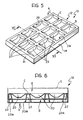
- the embodiment shown in Figures 5-7 in which the same reference numerals are retained for similar elements, includes a third portion D of the punched sheet 12 which, in the assembled configuration, is adapted to constitute the bottom of the box.
- the element 10 for holding and presenting the products can be used as the base of a box which can be completed by a suitable lid E, shown in broken outline in Figure 6.
- a finished box can be produced by the superposition of two elements 10, in which one glued lateral flap 21 can be used as a hinge.
- both the base and the lid of the box have cells for the improved restraint and protection of the products.
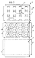
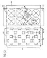
- the variant shown in Figures 10-13 may be used to advantage.
- the first portion A of the punched sheet 12 has annular punched lines 30 which are substantially square with curved sides 30a connected by rounded corners 30b.
- annular punched lines 30 which are substantially square with curved sides 30a connected by rounded corners 30b.
- two slits 32 arranged along the diagonals of the punched outline and a central square hole 33 define four, substantially-triangular support flaps 34 which, when the element 10 is assembled, are adapted to be inserted in corresponding holes 35 provided in the second portion B below the first portion A of the punched element 12 and arranged in correspondence with the curved sides 30a of the punched line 30.
- the flaps 34 form curved vertical walls which are adapted to fit the rounded products perfectly.
- the free appendages of the flaps 34 below the portion B of the punched sheet 12 act as feet and as supports for the upper frame wall C.
- the element 10 of the variant of Figures 10-13 can be inserted in the bottom of a box or can be used as the base of a box if a third portion of the punched sheet is included, as described in connection with the variants shown in Figures 5-7 or 8-9.
- the variant shown in Figures 14-18 although substantially similar to the solution shown in Figures 1-3, differs therefrom in that the punched element 12 does not have a second portion which can be bent but is assembled with an auxiliary sheet 40 which is glued or heat-sealed in correspondence with bent edges 42 and in correspondence with bent lateral flaps 43 of the punched sheet 12.
- the auxiliary sheet 40 also has a plurality of rectangular holes 44 for cooperating with support flaps 22 defined by the annular punched lines 12b and by the shaped slits 18.
Landscapes
- Engineering & Computer Science (AREA)
- Mechanical Engineering (AREA)
- Cartons (AREA)
- Food-Manufacturing Devices (AREA)
- Packages (AREA)
- Packaging Frangible Articles (AREA)
- Punching Or Piercing (AREA)
Abstract
Description
- The present invention relates to an element for holding and presenting confectionery products, particularly chocolates and the like, which is adapted to define a plurality of seats for the products, comprising a flat sheet of card or similar material having a plurality of four-sided punchings each defined by punched lines and, within the punched lines being provided with slits, whereby said punched lines define a plurality of holes in the sheet when the flaps defined between the slits and the punched lines are bent, and comprising an auxiliary sheet arranged beneath the flat sheet and having a plurality of holes.
- An element of the above type is disclosed by DE-U-89 07 594, in which the holes in the auxiliary sheet present the same dimension and form of the holes of the upper sheet in order to limit the bending of flaps. In this solution all the flaps are "floating", and in order to make the element or box more stiff it is necessary to connect the auxiliary sheet and the bottom of the box with an auxiliary bent flap glued to the bottom of the box.
- The object of the present invention is to provide an element of the type specified above which is stiff and reliable without using glue or similar.
- According to the invention, this object is achieved by virtue of the fact that the position of the holes on the auxiliary sheet coincide with the position of at least two opposite sides of the punchings and in which at least two corresponding opposite flaps obtained by bending said punched lines are inserted in order to keep them in an opened-out position.
- By virtue of these characteristics, the card element can fulfil the same function as a thermoformed cellular element of known type, providing considerable advantages in terms of cost and environmental impact. Moreover the flaps can be snap-engaged in the holes of the auxiliary sheet, obtaining a dimensionally stable and stiff element.
- Further advantages and characteristics of the holding and presentation element according to the invention will become clear from the detailed description which follows, with reference to the appended drawings, in which:
- Figure 1 is a perspective view of a holding and presentation element according to the invention,
- Figure 2 is a perspective view of the element of Figure 1 from below,
- Figure 3 is a section taken on the line III-III of Figure 1,
- Figure 4 is a plan view of the punched sheet from which the element of Figure 1 is made,
- Figure 5 is a perspective view of a first embodiment of the element of Figure 1,
- Figure 6 is a section taken on the line VI-VI of Figure 5,
- Figure 7 is a plan view of the punched sheet from which the element of Figure 5 is made,
- Figure 8 is a perspective view of a variant of the embodiment of Figure 5,
- Figure 9 is a cross-section of the element of Figure 8 in a closed configuration,
- Figure 10 is a perspective view of a third embodiment of the element according to the invention,
- Figure 11 is a perspective view of an element of Figure 8 from below,
- Figure 12 is a section taken on the line XII-XII of Figure 10,
- Figure 13 is a plan view of the punched sheet from which the element of Figure 10 is made,
- Figure 14 is a perspective view of a fourth embodiment of the element according to the invention,
- Figure 15 is a perspective view of the element of Figure 14 from below,
- Figure 16 is a section taken on the line XIV-XIV of Figure 14,
- Figure 17 is a view of an upper, flat punched element from which the element of Figure 14 is made,
- Figure 18 is a view of a lower, flat punched sheet from which the element of Figure 14 is made,
- With reference to the drawings, an element for holding and presenting confectionery products is generally indicated 10 and comprises a flat punched sheet of
card 12 with straight punchedlines 12a and a plurality of annularpunched lines 12b. These punched lines, which define lines of bending, are of the so-called half-cut type, that is, they are formed by cutting through half the thickness of thesheet 12. - With particular reference to the embodiment shown in Figures 1-4, the punched
sheet 12 has a first rectangular portion A bounded by the straight punchedlines 12a which are adapted to define lateral glueingflaps 14, and a second portion B which is joined to the first in correspondence with a straight punchedline 15 broken by substantially U-shapedslits 16. The second portion B of the punchedsheet 12 also has straight punchedlines 12a adapted to define lateral glueingflaps 17 for cooperating with thelateral flaps 14 in known manner. - The annular punched
lines 12b are substantially rectangular with rounded corners and are arranged in an ordered array in the first portion A of the punchedsheet 12.Slits 18 are provided within each annularpunched line 12b and comprise one I-shapedcentral portions 18a whose stems are parallel to and equidistant from the longer sides of the respective rectangular punchedlines 12b, and four connectingportions 18b between the tips of the ends of the I-shapedcentral portions 18a and the rounded corners V of thepunched lines 12b. Theslits 18 and the annular punchedline 12b thus define tworesilient flaps 20 of card in the form of isosceles trapezia and twosupport flaps 22 having portions which are also in the form of isosceles trapezia and the shorter bases of which extend to form rectangular portions, indicated 22a in the drawings. - The second portion B of the
punched card sheet 12 has a plurality ofrectangular holes 24 arranged in positions such that, when theelement 10 is assembled, they correspond to the longer sides of the rectangular punchedlines 12b to which thesupport flaps 22 are articulated. Adjacentrectangular holes 24 are joined by shorter central portions so are generally to define substantially double-T-shaped holes 25. - When the
element 10 is assembled, the second portion B of the punchedsheet 12 is bent underneath the first portion A along the straight punchedline 12a joining the first and second portions and along thepunched line 15. During this bending, theslits 16 definesupport portions 27 which project downwardly so as to keep the first portion A of thesheet 12 at a constant distance from a support plane, for example, the bottom of a box. After the second portion B has been bent relative to the first portion A and thelateral flaps support flaps 22 and theresilient flaps 20 are bent so as to form a plurality ofholes 28 in the first portion A of the punchedsheet 12 defining, with thebent flaps support flaps 22 are bent, theirrectangular ends 22a are fitted into respectiveretangular holes 24 so as to project below the plane of the second portion B of the punched sheet 12 (Figures 2 and 3) and have the function of forming a support on the bottom of the box. Therectangular end portions 22a of thesupport flaps 22 are therefore situated in the plane defined by the bent and gluedflaps 14 and thesupport portions 27 so as to keep the frames C defined by theholes 28 in thepunched sheet 12 at a predetermined distance from the lower support plane constituted, for example, by the bottom of a box. - The
resilient flaps 20 "float" and, by virtue of the resilient force biassing them towards a configuration in which they are coplanar with the frames C, help to keep the products in position by eliminating the clearance between the products and the seats S. The support flaps 22, on the other hand, are kept apart by virtue of their engagement in theholes 24 in the punchedsheet 12. - The embodiment shown in Figures 5-7, in which the same reference numerals are retained for similar elements, includes a third portion D of the punched
sheet 12 which, in the assembled configuration, is adapted to constitute the bottom of the box. In this embodiment, therefore, theelement 10 for holding and presenting the products can be used as the base of a box which can be completed by a suitable lid E, shown in broken outline in Figure 6. - Alternatively, a finished box can be produced by the superposition of two
elements 10, in which one gluedlateral flap 21 can be used as a hinge. In this variant, shown in Figures 8 and 9, both the base and the lid of the box have cells for the improved restraint and protection of the products. - For confectionery products of rounded shape, the variant shown in Figures 10-13 may be used to advantage. In this variant, the first portion A of the punched
sheet 12 has annular punched lines 30 which are substantially square withcurved sides 30a connected byrounded corners 30b. Within each punched line 30, twoslits 32 arranged along the diagonals of the punched outline and acentral square hole 33 define four, substantially-triangular support flaps 34 which, when theelement 10 is assembled, are adapted to be inserted incorresponding holes 35 provided in the second portion B below the first portion A of the punchedelement 12 and arranged in correspondence with thecurved sides 30a of the punched line 30. The curved lines of bending in correspondence with the punchedsides 30a give the upper frame wall C of the element 10 a wavy appearance, as shown in Figure 10. Moreover, in their opened-out configuration, theflaps 34 form curved vertical walls which are adapted to fit the rounded products perfectly. The free appendages of theflaps 34 below the portion B of the punchedsheet 12 act as feet and as supports for the upper frame wall C. To advantage, theelement 10 of the variant of Figures 10-13 can be inserted in the bottom of a box or can be used as the base of a box if a third portion of the punched sheet is included, as described in connection with the variants shown in Figures 5-7 or 8-9. - The variant shown in Figures 14-18, although substantially similar to the solution shown in Figures 1-3, differs therefrom in that the punched
element 12 does not have a second portion which can be bent but is assembled with anauxiliary sheet 40 which is glued or heat-sealed in correspondence withbent edges 42 and in correspondence with bentlateral flaps 43 of the punchedsheet 12. Theauxiliary sheet 40 also has a plurality ofrectangular holes 44 for cooperating withsupport flaps 22 defined by the annular punchedlines 12b and by theshaped slits 18. - The above description shows clearly the advantages of the holding and presentation element according to the invention which, by virtue of its particular characteristics, can be used not only as an accessory for a box but as an integral and structural part of the box itself.
Claims (6)
- An element for holding and presenting confectionery products, particularly chocolates and the like, which is adapted to define a plurality of seats for the products, comprising a flat sheet (12) of card or similar material having a plurality of four-sided punchings (12b, 30) each defined by punched lines and, within the punched lines (12b 30) being provided with slits (18, 32), whereby said punched lines define a plurality of holes (28) in the sheet (12) when the flaps (20, 22, 34) defined between the slits (18, 32) and the punched lines (12b, 30) are bent; and comprising an auxiliary sheet (12 B') arranged beneath the flat sheet (12 A) and having a plurality of holes (24) characterised in that the position of the holes (24, 35) on the auxiliary sheet (12 B) coincide with the position of at least two opposite sides of the punching and in which at least two corresponding opposite flaps obtained by bending said punched lines (22, 34) are inserted in order to keep them in an opened-out position.
- An element according to Claim 1, characterised in that the flat sheet (12 A) has an integral base sheet (12 D) which is adapted to be bent beneath the auxiliary sheet (12 B') and against which the flap (22, 34) inserted in the holes (25, 35) of the auxiliary sheet (12 B) bear in the assembled condition of the element (10).
- An element according to Claim 2, characterised in that each punching (12b) is substantially rectangular and in that the slits (18) within each punching (12b) have an I-shaped central portion (18a) arranged with its stem equidistant from and parallel to the longer sides of the punched line (12b) and four connecting portions (18b) between the tips of the ends of the I-shaped central portion (18a) and the corners (V) of the punched line (12b), whereby there are defined two resilient trapezoidal flaps (20), in correspondence with the shorter sides of the punching (12b) and two support flaps (22), inserted in the corresponding holes (25) of the auxiliary sheet (12 B), each having a trapezoidal portion adjacent to the edge of the punching (12b) and a rectangular portion (22a) connected to the trapezoidal portion.
- An element according to Claim 3, characterised in that the auxiliary sheet (12 B) is glued or heat-sealed to bent side flaps (43) of the flat sheet (12 A) at a predetermined distance therefrom.
- An element according to Claim 3, characterised in that it has a lateral flap (21) glued or heat-sealed to a similar element (10) so as to define a hinge between a base and a lid, both provided with seats for products.
- An element according to Claim 1, characterised in that each punching (30) is substantially square with curved sides (30a) connected by rounded corners (30b), and in that the slits (32) within each punched line (30) are arranged diagonally so as to define substantially triangular flaps (34).
Priority Applications (1)
| Application Number | Priority Date | Filing Date | Title |
|---|---|---|---|
| AT90830092T ATE97088T1 (en) | 1990-01-10 | 1990-03-13 | CUT-OUT CARDBOARD PLATE FOR HOLDING AND DISPLAYING CANDY AND SIMILAR PRODUCTS. |
Applications Claiming Priority (2)
| Application Number | Priority Date | Filing Date | Title |
|---|---|---|---|
| IT6701290 | 1990-01-10 | ||
| IT67012A IT1239850B (en) | 1990-01-10 | 1990-01-10 | DIE CARDBOARD ELEMENT FOR HOLDING AND PRESENTING DESSERIES AND SIMILAR PRODUCTS |
Publications (2)
| Publication Number | Publication Date |
|---|---|
| EP0441102A1 EP0441102A1 (en) | 1991-08-14 |
| EP0441102B1 true EP0441102B1 (en) | 1993-11-10 |
Family
ID=11298882
Family Applications (1)
| Application Number | Title | Priority Date | Filing Date |
|---|---|---|---|
| EP90830092A Expired - Lifetime EP0441102B1 (en) | 1990-01-10 | 1990-03-13 | Punched cardboard element for keeping and showing sweets and the like |
Country Status (5)
| Country | Link |
|---|---|
| EP (1) | EP0441102B1 (en) |
| AT (1) | ATE97088T1 (en) |
| DE (1) | DE69004564T2 (en) |
| ES (1) | ES2046767T3 (en) |
| IT (1) | IT1239850B (en) |
Families Citing this family (32)
| Publication number | Priority date | Publication date | Assignee | Title |
|---|---|---|---|---|
| DE4025963A1 (en) * | 1990-08-16 | 1992-02-20 | Jacobs Suchard Ag | PACKAGING FOR CONFECTIONERY |
| FR2687648B1 (en) * | 1992-02-21 | 1994-05-20 | Legrand | PACKING GRID FOR SNAP-ON DEVICES. |
| IT1258358B (en) * | 1992-02-25 | 1996-02-26 | Saffapack Srl | ALVEOLAR CONTAINER. |
| IT1263213B (en) * | 1992-03-16 | 1996-08-05 | Saffapack Srl | BOX, IN PARTICULAR FOR SWEET PRODUCTS OF THE CHOCOLATE TYPE. |
| DE9312105U1 (en) * | 1993-07-06 | 1994-01-05 | Scholz, Manfred, 64289 Darmstadt | Packaging insert for chocolate packaging and the like. |
| EP0937657A1 (en) * | 1998-02-24 | 1999-08-25 | BARTOLINI SAS di Bartolini Adriano & C. | Product combining a sweet speciality and a disposable game involving questions on works of art |
| AU1842301A (en) | 1999-11-19 | 2001-06-04 | Susanne Pfaffenbichler | Packaging for fragile or crushable goods |
| EP1136370A1 (en) | 2000-03-21 | 2001-09-26 | Societe Des Produits Nestle S.A. | Display package for food items |
| RU2225820C1 (en) * | 2002-07-12 | 2004-03-20 | Общество с ограниченной ответственностью "Основание-2" | Correxy |
| RU2236369C2 (en) * | 2002-10-02 | 2004-09-20 | Общество с ограниченной ответственностью "Основание-2" | Correxy |
| RU2256592C2 (en) * | 2003-07-07 | 2005-07-20 | Общество с ограниченной ответственностью "Основание-2" | Correx |
| FR2860505B1 (en) * | 2003-10-03 | 2006-01-27 | Knauf Snc | PACKAGING FOR FRESH FOODSTUFFS, ESPECIALLY PLATE OF RAVIOLIS |
| RU2255885C1 (en) * | 2003-12-30 | 2005-07-10 | Общество с ограниченной ответственностью "Основание-2" | Apron |
| ITMI20041640A1 (en) * | 2004-08-10 | 2004-11-10 | Cartotecnica Esse Bi S R L | TRAY AND PROCEDURE FOR THE REALIZATION OF THE SAME |
| FR2902410B1 (en) * | 2006-06-16 | 2008-09-12 | Smurfit Kappa France Sas Soc P | PACKAGING OF TRAY OR TRAY TYPE IN SEMI-RIGID MATERIAL |
| ITTO20090136U1 (en) * | 2009-09-24 | 2011-03-25 | Seda Spa | ZUSCHNITT UND AUS DIESEM HERGESTELLTE VERPACKUNG |
| RU2495808C1 (en) * | 2012-08-07 | 2013-10-20 | Виктор Михайлович Коршунов | Box for confectionary items and method of its packaging |
| ITTO20121146A1 (en) * | 2012-12-24 | 2014-06-25 | Soremartec Sa | POSITIONING AND RETENTION DEVICE FOR SWEETENED PRODUCTS AND TOGETHER WITH LOCKED PLANS FOR THE REALIZATION OF SUCH A DEVICE |
| GB2520989A (en) * | 2013-12-06 | 2015-06-10 | Mondelez Uk R & D Ltd | Packaging |
| JP2016043974A (en) * | 2014-08-25 | 2016-04-04 | 王子ホールディングス株式会社 | Paper holder |
| US10843841B2 (en) * | 2016-12-27 | 2020-11-24 | Broadway Holdings Iv, Llc | Device for moving and storing potted plants and other objects having a base |
| CN108455079B (en) * | 2018-03-21 | 2019-11-01 | 连云港市鼎尚包装有限公司 | A kind of fruit packaging cushion |
| CN109051169A (en) * | 2018-08-08 | 2018-12-21 | 珠海格力电器股份有限公司 | packaging structure and packaging assembly |
| GB2580609A (en) * | 2019-01-15 | 2020-07-29 | Multi Packaging Solutions Uk Ltd | Carrier |
| DE202019101008U1 (en) * | 2019-02-21 | 2020-05-25 | A&R Carton Gmbh | Carrier made of foldable flat material for preferably small pieces |
| GB2589053B (en) * | 2019-07-24 | 2023-08-30 | Concept Packaging Services Ltd | Improvements in and relating to fitments |
| GB2589146A (en) | 2019-11-25 | 2021-05-26 | Multi Packaging Solutions Uk Ltd | Tray |
| CN215884413U (en) * | 2021-07-31 | 2022-02-22 | 深圳市裕同包装科技股份有限公司 | Packing box and paperboard structure |
| US12116182B2 (en) | 2021-07-31 | 2024-10-15 | ShenZhen YUTO Packaging Technology Co., Ltd | Packaging box and paperboard structure |
| DE102022119953A1 (en) * | 2022-08-08 | 2024-02-08 | Van Genechten Packaging N.V. | Packaging |
| DE102023119866B4 (en) * | 2023-07-26 | 2025-06-26 | Mayr-Melnhof Karton Ag | Packaging insert, packaging, set for producing a packaging insert and method and device for producing a packaging insert |
| DE202024104761U1 (en) * | 2024-08-22 | 2025-08-25 | Mayr-Melnhof Karton Ag | Packaging insert, packaging and cutting for the production of a packaging insert |
Family Cites Families (5)
| Publication number | Priority date | Publication date | Assignee | Title |
|---|---|---|---|---|
| DE738917C (en) * | 1938-12-14 | 1943-09-04 | Lothar Alexander Fritz Hilbric | Box for ampoules and like |
| FR1016194A (en) * | 1950-04-12 | 1952-11-04 | Packaging | |
| GB1264412A (en) * | 1969-06-04 | 1972-02-23 | ||
| DE8907593U1 (en) * | 1989-06-21 | 1989-11-02 | Hermann Schött GmbH Offsetdruckerei, 4050 Mönchengladbach | Packaging insert |
| DE8907594U1 (en) * | 1989-06-21 | 1989-11-02 | Hermann Schött GmbH Offsetdruckerei, 4050 Mönchengladbach | Packaging insert |
-
1990
- 1990-01-10 IT IT67012A patent/IT1239850B/en active IP Right Grant
- 1990-03-13 ES ES199090830092T patent/ES2046767T3/en not_active Expired - Lifetime
- 1990-03-13 DE DE69004564T patent/DE69004564T2/en not_active Expired - Fee Related
- 1990-03-13 EP EP90830092A patent/EP0441102B1/en not_active Expired - Lifetime
- 1990-03-13 AT AT90830092T patent/ATE97088T1/en not_active IP Right Cessation
Also Published As
| Publication number | Publication date |
|---|---|
| DE69004564T2 (en) | 1994-06-01 |
| IT1239850B (en) | 1993-11-15 |
| ES2046767T3 (en) | 1994-02-01 |
| EP0441102A1 (en) | 1991-08-14 |
| DE69004564D1 (en) | 1993-12-16 |
| ATE97088T1 (en) | 1993-11-15 |
| IT9067012A0 (en) | 1990-01-10 |
| IT9067012A1 (en) | 1991-07-11 |
Similar Documents
| Publication | Publication Date | Title |
|---|---|---|
| EP0441102B1 (en) | Punched cardboard element for keeping and showing sweets and the like | |
| EP0387316B1 (en) | Merchandise support assembly and hook suitable for use therewith | |
| US5110037A (en) | Container and method of making same | |
| EP0160730A1 (en) | Cardboard container | |
| EP0036785A1 (en) | Packaging containers | |
| JP3008254U (en) | Packaging container | |
| JPH061335A (en) | Packing holding panel and packing device | |
| JPH05338644A (en) | Packaging container for exhibition and sale, and manufacture thereof | |
| JP2798444B2 (en) | package | |
| JPS58116528U (en) | folding box | |
| JP3203477B2 (en) | Container with backing and method of manufacturing the same | |
| KR910007073Y1 (en) | Packing box with fixing member | |
| JPS6013831Y2 (en) | potted flower package | |
| WO1995027658A1 (en) | Cake box | |
| JPS6219580Y2 (en) | ||
| JP3037809U (en) | Product protection buffer box | |
| JPH0635936Y2 (en) | Packaging box for electric fan | |
| JPH0331731Y2 (en) | ||
| JPS5937461Y2 (en) | Connection box for disconnection | |
| JPS624511Y2 (en) | ||
| JPS5911071Y2 (en) | toothbrush container | |
| JPH082152Y2 (en) | Bobbin holder for winding winding | |
| JPS6244948Y2 (en) | ||
| JPS5821377Y2 (en) | display packaging box | |
| JPS6215132Y2 (en) |
Legal Events
| Date | Code | Title | Description |
|---|---|---|---|
| PUAI | Public reference made under article 153(3) epc to a published international application that has entered the european phase |
Free format text: ORIGINAL CODE: 0009012 |
|
| AK | Designated contracting states |
Kind code of ref document: A1 Designated state(s): AT BE CH DE DK ES FR GB GR IT LI LU NL SE |
|
| 17P | Request for examination filed |
Effective date: 19911011 |
|
| 17Q | First examination report despatched |
Effective date: 19930205 |
|
| GRAA | (expected) grant |
Free format text: ORIGINAL CODE: 0009210 |
|
| AK | Designated contracting states |
Kind code of ref document: B1 Designated state(s): AT BE CH DE DK ES FR GB GR IT LI LU NL SE |
|
| PG25 | Lapsed in a contracting state [announced via postgrant information from national office to epo] |
Ref country code: GR Free format text: LAPSE BECAUSE OF FAILURE TO SUBMIT A TRANSLATION OF THE DESCRIPTION OR TO PAY THE FEE WITHIN THE PRESCRIBED TIME-LIMIT Effective date: 19931110 Ref country code: AT Effective date: 19931110 |
|
| REF | Corresponds to: |
Ref document number: 97088 Country of ref document: AT Date of ref document: 19931115 Kind code of ref document: T |
|
| ITF | It: translation for a ep patent filed | ||
| REF | Corresponds to: |
Ref document number: 69004564 Country of ref document: DE Date of ref document: 19931216 |
|
| REG | Reference to a national code |
Ref country code: ES Ref legal event code: FG2A Ref document number: 2046767 Country of ref document: ES Kind code of ref document: T3 |
|
| ET | Fr: translation filed | ||
| PG25 | Lapsed in a contracting state [announced via postgrant information from national office to epo] |
Ref country code: DK Effective date: 19940313 |
|
| PG25 | Lapsed in a contracting state [announced via postgrant information from national office to epo] |
Ref country code: SE Free format text: LAPSE BECAUSE OF NON-PAYMENT OF DUE FEES Effective date: 19940314 Ref country code: ES Free format text: LAPSE BECAUSE OF EXPIRATION OF PROTECTION Effective date: 19940314 |
|
| PG25 | Lapsed in a contracting state [announced via postgrant information from national office to epo] |
Ref country code: LU Free format text: LAPSE BECAUSE OF NON-PAYMENT OF DUE FEES Effective date: 19940331 Ref country code: BE Effective date: 19940331 |
|
| PLBE | No opposition filed within time limit |
Free format text: ORIGINAL CODE: 0009261 |
|
| STAA | Information on the status of an ep patent application or granted ep patent |
Free format text: STATUS: NO OPPOSITION FILED WITHIN TIME LIMIT |
|
| BERE | Be: lapsed |
Owner name: CARTOTECNICA CHIERESE S.P.A. Effective date: 19940331 |
|
| PG25 | Lapsed in a contracting state [announced via postgrant information from national office to epo] |
Ref country code: NL Effective date: 19941001 |
|
| 26N | No opposition filed | ||
| NLV4 | Nl: lapsed or anulled due to non-payment of the annual fee | ||
| EUG | Se: european patent has lapsed |
Ref document number: 90830092.4 Effective date: 19941010 |
|
| PGFP | Annual fee paid to national office [announced via postgrant information from national office to epo] |
Ref country code: GB Payment date: 19990216 Year of fee payment: 10 |
|
| PGFP | Annual fee paid to national office [announced via postgrant information from national office to epo] |
Ref country code: CH Payment date: 19990224 Year of fee payment: 10 |
|
| PGFP | Annual fee paid to national office [announced via postgrant information from national office to epo] |
Ref country code: DE Payment date: 19990226 Year of fee payment: 10 |
|
| PGFP | Annual fee paid to national office [announced via postgrant information from national office to epo] |
Ref country code: FR Payment date: 19990330 Year of fee payment: 10 |
|
| REG | Reference to a national code |
Ref country code: ES Ref legal event code: FD2A Effective date: 19990601 |
|
| PG25 | Lapsed in a contracting state [announced via postgrant information from national office to epo] |
Ref country code: GB Free format text: LAPSE BECAUSE OF NON-PAYMENT OF DUE FEES Effective date: 20000313 |
|
| PG25 | Lapsed in a contracting state [announced via postgrant information from national office to epo] |
Ref country code: LI Free format text: LAPSE BECAUSE OF NON-PAYMENT OF DUE FEES Effective date: 20000331 Ref country code: CH Free format text: LAPSE BECAUSE OF NON-PAYMENT OF DUE FEES Effective date: 20000331 |
|
| GBPC | Gb: european patent ceased through non-payment of renewal fee |
Effective date: 20000313 |
|
| REG | Reference to a national code |
Ref country code: CH Ref legal event code: PL |
|
| PG25 | Lapsed in a contracting state [announced via postgrant information from national office to epo] |
Ref country code: FR Free format text: LAPSE BECAUSE OF NON-PAYMENT OF DUE FEES Effective date: 20001130 |
|
| REG | Reference to a national code |
Ref country code: FR Ref legal event code: ST |
|
| PG25 | Lapsed in a contracting state [announced via postgrant information from national office to epo] |
Ref country code: DE Free format text: LAPSE BECAUSE OF NON-PAYMENT OF DUE FEES Effective date: 20010103 |
|
| PG25 | Lapsed in a contracting state [announced via postgrant information from national office to epo] |
Ref country code: IT Free format text: LAPSE BECAUSE OF NON-PAYMENT OF DUE FEES;WARNING: LAPSES OF ITALIAN PATENTS WITH EFFECTIVE DATE BEFORE 2007 MAY HAVE OCCURRED AT ANY TIME BEFORE 2007. THE CORRECT EFFECTIVE DATE MAY BE DIFFERENT FROM THE ONE RECORDED. Effective date: 20050313 |