EP0441153A2 - Procedure and device for absolute interferometric testing of flat surfaces - Google Patents
Procedure and device for absolute interferometric testing of flat surfaces Download PDFInfo
- Publication number
- EP0441153A2 EP0441153A2 EP91100644A EP91100644A EP0441153A2 EP 0441153 A2 EP0441153 A2 EP 0441153A2 EP 91100644 A EP91100644 A EP 91100644A EP 91100644 A EP91100644 A EP 91100644A EP 0441153 A2 EP0441153 A2 EP 0441153A2
- Authority
- EP
- European Patent Office
- Prior art keywords
- incidence
- plane
- interferometer
- plane surface
- angle
- Prior art date
- Legal status (The legal status is an assumption and is not a legal conclusion. Google has not performed a legal analysis and makes no representation as to the accuracy of the status listed.)
- Granted
Links
Images


Classifications
-
- G—PHYSICS
- G01—MEASURING; TESTING
- G01B—MEASURING LENGTH, THICKNESS OR SIMILAR LINEAR DIMENSIONS; MEASURING ANGLES; MEASURING AREAS; MEASURING IRREGULARITIES OF SURFACES OR CONTOURS
- G01B11/00—Measuring arrangements characterised by the use of optical techniques
- G01B11/30—Measuring arrangements characterised by the use of optical techniques for measuring roughness or irregularity of surfaces
- G01B11/306—Measuring arrangements characterised by the use of optical techniques for measuring roughness or irregularity of surfaces for measuring evenness
Definitions
- the invention relates to a method and a device for the interferometric absolute inspection of plane surfaces, in which the wavefront interference caused by the interferometer is determined and taken into account in the later evaluation.
- interferometric measuring methods are highly precise examination of sample surfaces.
- a computer-aided evaluation of the interferograms enables measurement resolutions perpendicular to the sample surface that are better than approx. 1: 100 of the light wavelength used.
- interferometry only allows the relative differences between two sample surfaces to be determined.
- a calibration of the interferometer is required for an absolute test, i.e. the comparison of a sample surface relative to a mathematical level. For this, however, the deviations of a calibration surface relative to a mathematical level must be known with corresponding accuracy.
- This object is achieved according to the characterizing part of the first claim by simultaneously inserting two plane surfaces to be tested at different incidence angles into the measuring beam path of the interferometer, by determining the wavefront interference caused by both plane surfaces and by changing at least one angle of incidence.
- the two plane surfaces to be tested are inserted into the interferometer simultaneously. This leaves the Obtain orientation of the two interferometer mirrors relative to each other. Since changing an angle of incidence does not change the orientation of the two plane surfaces relative to one another, the method according to the invention avoids the mirroring problem mentioned at the outset. Therefore an area-wide absolute examination is possible.
- the absolute test takes place in at least three procedural steps:
- a first procedural step an interferogram of the empty interferometer is recorded and a first phase map, i.e. the phase difference between the measuring beam and the reference beam, created as a function of the location.
- the two plane surfaces to be tested are brought into the measuring beam path of the interferometer at different incidence angles, and a second phase map is created.
- a third step at least one angle of incidence is changed and a third phase map is created. The order of the process steps is irrelevant.
- phase stepping method for example, a time shift of the phase position is required, for example, by shifting the reference mirror along the optical axis.
- phase values of the first phase map can simply be subtracted from the phase values of the two remaining phase maps at each measuring point, whereby the influence of the interferometer on these phase maps is eliminated. Only linear systems of equations then have to be solved for further evaluation, that is to say for the calculation of the wavefront disturbances caused in each case by a plane surface. This can be done in a computer with commercial software.
- the system of equations to be solved is simplified if the incidence angles of both plane surfaces are changed and if the cosine of one incidence angle corresponds to an integer multiple of the cosine of the other incidence angle. Local interpolation between the measuring points is then not necessary. This also applies if the interferograms are recorded by the camera only on a discrete pixel grid. However, the statistical uncertainties with which the wavefront disturbances are determined increase with large integer multiples. Therefore, the integer multiple should be 2.
- the change in the angle of incidence should correspond to a swapping of the angle of incidence. This can be done by interchanging the two flat surfaces themselves. The wavefront disturbances of both plane surfaces are then determined with the same statistical uncertainty.
- the flat surface with the smaller incidence angle should be moved, since this flat surface is usually not fully illuminated.
- the shift should be an integer multiple of the pixel spacing.
- the integer multiple of the pixel spacing should be maintained to at least 1/10 of the pixel spacing.
- the method according to the invention can be carried out both with a Michelson interferometer and with a Fizeau interferometer.
- a Fizeau interferometer enables a more compact design.
- interferometer is arranged on a base plate, as is customary.
- This base plate is then provided with a number of positioning aids which indicate to the user in which positions the plane surfaces and the interferometer mirror of the measuring beam path are to be brought for the individual process steps.
- Rails for three-point storage can be provided as simple positioning aids that ensure high reproducibility.
- the user of the interferometer is then able to measure a plane surface absolutely or to calibrate his interferometer at any time by using the absolutely tested plane surface as an interferometer mirror and storing the wavefront interference caused by it. There are then no special requirements for the long-term stability of such an arrangement.
- one of the two flat surfaces is a strip grid. Depending on the angle of incidence, different reflection coefficients of this plane surface can then be set.
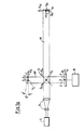
- FIG. 1a The beam path of a Michelson interferometer is shown schematically in FIG. 1a.
- a laser designated (L) generates a parallel light beam, which is expanded by a telescope (T) and by a beam splitter (S) into a measuring beam path (M) and one Reference beam path (RF) is steered.
- a first interferometer mirror (I) reflects the reference beam path (RF) and a second interferometer mirror (H) reflects the measuring beam path back into itself. Both reflected beam paths are directed from the beam splitter (S) to the camera sensor (K).
- the camera sensor (K) records a spatially resolved image of the interference of the reference beam with the measuring beam, an interferogram.
- the optical path length in the reference beam path (RF) and in the measuring beam path (M) are different, but the path length difference is smaller than the coherence length of the laser (L).
- the interferometer mirror (I) in the reference beam path (RF) is tilted out of the vertical incidence by a small angle ( ⁇ ), which is shown here enlarged.
- ⁇ a small angle
- f o a spatial carrier frequency
- each reflecting plane surface (H, I, S) is assigned a right-handed coordinate system, the x-axes of which are in the plane of the drawing and the z-axes of which are parallel to the surface normals.
- the coordinate axes of each plane surface are provided with the reference symbols of the respective plane surface as an index. So with (x I , y I , z I ) the coordinate system of the interferometer mirror (I) of the reference beam path (RF), with (x H , y H , z H ) the coordinate system of the interferometer mirror (H) in the measuring beam path (M) and denoted by (x S , y S , z S ) the coordinate system of the beam splitter (S).
- FIGS. 1b and 1c the same Michelson interferometer is shown in FIGS. 1b and 1c as in FIG. 1a. For this reason, identical components are provided with identical reference numerals as in FIG. 1a.
- two plane surfaces (A, B) to be tested are arranged one behind the other in the measuring beam path (M) of the interferometer at different incidence angles ( ⁇ , ⁇ ) in FIGS. 1b and 1c.
- the measuring beam path (M) is first reflected at the angle ( ⁇ ) on the first plane surface (A) and then at the angle ( ⁇ ) on the second plane surface (B).
- the measuring beam path (M) is then reflected back into itself at the interferometer mirror (H).
- the measuring beam path (M) in FIGS. 1b and 1c has the same length as the measuring beam path (M) in FIG. 1a.
- Fig. 1c the two plane surfaces (A, B) are arranged rotated relative to Fig. 1b so that the measuring beam path on the first plane surface (A) at the angle ( ⁇ ) and on the second plane surface (B) at the angle ( ⁇ ) is reflected.
- a right-handed coordinate system (x A , y A , z A ) or (x B , y B , z B ), whose z axes (z A , z B ) are now also assigned to the two plane surfaces (A, B ). perpendicular to the respective flat surface and its x-axes (x A , x B ) in the drawing plane parallel to the respective flat surface (A, B).
- the interferometer mirrors (H, I) are oriented in exactly the same way as in FIG. 1a. There is therefore no problem of mirroring.
- Two more interferograms are recorded after the first plane surface (A) by a distance x A , which corresponds to an integer multiple of the pixel spacing on the first plane surface (A) in the x A direction, in the positive x A direction (arrow Pb2) or has been moved in the negative x A direction (arrow Pb3).
- the total wavefront disturbances measured are: after shifting in the direction of the arrow (P b2 ) and after shifting the plane surface (A) in the direction of the arrow (Pb3).
- the measured wavefront disturbances in the plane of the camera sensor (K) result accordingly taking into account the now reversed angle of incidence: for the unmoved case, after shifting in the direction of the arrow (P c2 ) (+ x B direction) and after shifting in the direction of the arrow (P c3 ) (- x B direction)
- the further evaluation takes place by solving this system of equations according to the contributions ⁇ A and ⁇ B of the wavefront disturbances of the two plane surfaces (A, B).
- the discrete pixel grid of the camera sensor (K) is thus mapped onto discrete pixel grids on the plane surfaces (A, B), which are identical on both plane surfaces and during all process steps. This can be illustrated clearly with the help of the detailed representations in FIGS. 1d and 1e, in which five discrete pixels (K ⁇ 2) to (K2) of the camera sensor (K) are considered in the x direction. As shown in Fig.
- pixels of this plane surface (A) are each with an index that is smaller by the number 2, ie the pixels (A ⁇ 4, A ⁇ 3, A ⁇ 2, A ⁇ 1, A0), on the even-numbered pixels (B4, B2, B0, B ⁇ 2, B ⁇ 4) of the second plane surface (B) and on the pixels (K ⁇ 2 - K2) of the camera sensor (K) shown.
- pixels of the first plane surface (A) with an index larger by two ie the pixels (A (, A1, A2, A3, A4), on the same even-numbered pixels (B4, B2, B0, B ⁇ 2, B ⁇ 4) of the second plane surface (B) and on the pixels (K ⁇ 2 - K2) of the camera sensor (K).
- Fig. Le the image of the pixels (K ⁇ 2, K ⁇ 1, K0, K1, K2) of the camera sensor (K) is shown when the angle of incidence ( ⁇ , ⁇ ) of the two plane surfaces (A, B) interchanged are. Then only the even-numbered pixels (A ⁇ 4, A ⁇ 2, A0, A2, A4) of the first plane surface (A) are shown.
- the two planar surfaces (A, B) can be assigned a clear, discrete pixel grid (A ⁇ 4 - A4) or (B ⁇ 4 - B4), and that when recording the interferograms, points of these pixel grids are always on top of each other and be imaged on the pixels (K ⁇ 2 - K2) of the camera sensor (K). An interpolation between the pixels is not necessary.
- Equation (1) - (7) The system of equations consisting of the above seven equations (equation (1) - (7)) can be in the form to be written.
- the error matrix (F) is then a matrix with 4 m -2 columns and 6 m rows, where m is the number of Pixel of the camera sensor (K) in the x direction.
- m is the number of Pixel of the camera sensor (K) in the x direction.
- the linear system of equations (8) is then to be solved for each column of the camera sensor (K) in the y direction.
- the system of equations must be solved 512 times.
- the error matrix (F) is independent of x and y and is therefore a constant.
- the individual coefficients of (F) are either 0, cos ⁇ or cos ⁇ .
- the constant weight matrix (G) is stored in the computer (R), which enables a quick calculation of the wavefront interference ⁇ A (x A , y A ), ⁇ B (x B , y B ) in all points (x A , y A ) of the first flat surface (A) and in all points (x B , y B ) of the second flat surface (B).
- the square root of the square sum of the coefficients of a row of the weight matrix (G) is a measure of the statistical uncertainty with which the wavefront disturbances ( ⁇ A ) and ( ⁇ B ) are determined. Since the weight matrix (G) is the same for all columns of the camera sensor (K) in the y direction, the statistical uncertainty is also independent of the respective y value. It can be shown that the statistical uncertainty in the middle of the first plane surfaces (A) is only slightly larger than the uncertainty with which the entire wavefront disturbances ( ⁇ a1 , ⁇ b1 , ⁇ b2 , ⁇ b3 , ⁇ c1 , ⁇ c2 , ⁇ c3 ) in the middle of the first plane surfaces (A).
- FIGS. 1a to 1e show a second exemplary embodiment for the absolute test of plane surfaces, which essentially consists of a Fizeau interferometer. Most of the components in this exemplary embodiment correspond to those from FIGS. 1a to 1e. They are therefore provided with the same reference numerals with an index 6.
- the measuring beam path and the reference beam path in a Fizeau interferometer have a common area (G6).
- the interferometer mirror of the reference beam path (I6) is partially permeable and wedge-shaped.
- a spatial frequency filter (F6) is arranged in front of the camera sensor (K6). The light reflected on the front surface (I 6V ) of the interferometer mirror (I6) is filtered out.
- the measuring method is analogous to that described in the description of FIGS. 1a to 1e.
- the topography of the plan areas (A6, B6) can be graphically displayed on a monitor (MO6) after the plan check and after evaluation by the computer (R6).
- the first plane surface (A6) is arranged at the angle of incidence ( ⁇ 6) and the second plane surface (B6) at the angle of incidence ( ⁇ 6) in the measuring beam path (M6). Both these two flat surfaces (A6, B6) and the interferometer mirror (H6) are attached to mirror holders (P A , P B , P H ).
- T-shaped rails (J61, J62, J63, J64) are arranged on the base plate (Bp6) T-shaped rails (J61, J62, J63, J64) are arranged. which are each provided with grooves (N61, N62, N63, N64). In these grooves (N61 - N64) balls, not shown, can engage on the underside of the mirror holder (P A , P B , P H ). which causes a three-point bearing.
- Corresponding rails are also provided under the mirror holders (P A , P B , P H ) in the positions shown, but they are covered by the mirror holders (P A , P B , P H ) and are therefore not shown.
- the mirror holder (P A ) which carries the first flat surface (A6) on the rail (J61) and the mirror holder (P B ), the second Flat surface (B6) carries, placed on the rail (J64).
- the interferometer mirror (H6) carrying mirror holder (P H ) is placed on the rail (J63).
- the two flat surfaces (A6, B6) are removed from the measuring beam path of the interferometer and the interferometer mirror (H6) is placed on the rail (J62).
- the mirror holders (P A , P B ) of the two flat surfaces (A6, B6) are each provided with a ⁇ m screw (M A , M B ), which shifts the two flat surfaces (A6, B6) in the plane of the drawing and parallel to it Respective plane surface (A6, B6) enables.
- the interferometer can be calibrated by inserting one of the two flat surfaces (A6, B6) into the interferometer instead of the interferometer mirror (H6).
- the problem with the Fizeau interferometer is that the plane surfaces to be tested (A6, B6) should on the one hand have the largest possible reflection coefficient so that high-contrast interferograms can be recorded.
- the interferometer mirror (H6) should only have a small reflection coefficient.
- the second plane surface (B6) has a division of alternating opaque and reflective strips.
- the reflective stripes should be wider than the opaque stripes.
- the plane surface (B6) is then examined for absolute testing in the 0th diffraction order. It then has a large reflection coefficient.
- To calibrate the interferometer it is then pivoted in place of the interferometer mirror (H6) in the interferometer so that the light reflected in the ⁇ 1st diffraction order transmits the spatial frequency filter (F6).
- the reflection coefficient of the ⁇ 1st diffraction order is considerably lower than the reflection coefficient of the 0 diffraction order.
- Wavefront interference caused by pitch errors can be eliminated by taking a first measurement in the + 1st diffraction order and a second measurement in the - 1st diffraction order.
- the beam paths are shown in such a way that symmetrical test conditions are present for both plane surfaces (A, B, A6, B6).
- the interferometer mirror (H, H6) can be arranged as close as possible to the second plane surface (B, B6).
- the second plane surface (B, B6) can be imaged on the camera sensor (K, K6) by means of a telescope which is to be provided between the beam splitter (S, S6) and the camera sensor (K, K6), so that this second plane surface ( B, B6) can be checked with greater accuracy.
Landscapes
- Physics & Mathematics (AREA)
- General Physics & Mathematics (AREA)
- Instruments For Measurement Of Length By Optical Means (AREA)
- Length Measuring Devices By Optical Means (AREA)
Abstract
Gegenstand der Erfindung ist ein einfaches Verfahren und eine Vorrichtung zur Absolutprüfung von Planflächen. Es sieht vor, daß gleichzeitig zwei Planflächen (A₆, B₆) unter schräger Inzidenz in den Meßstrahlengang eines Interferometers eingebracht werden. Es werden die Interferogramme, die sich bei unterschiedlichen Inzidenzwinkeln (α₆, β₆) und bei Verschiebung der beiden Planflächen ergeben, rechnerisch ausgewertet.
Description
Die Erfindung betrifft ein Verfahren und eine Vorrichtung zur interferometrischen Absolutprüfung von Planflächen, bei dem die durch das Interferometer verursachten Wellenfrontstörungen ermittelt und bei der späteren Auswertung berücksichtigt werden.The invention relates to a method and a device for the interferometric absolute inspection of plane surfaces, in which the wavefront interference caused by the interferometer is determined and taken into account in the later evaluation.
Eine Anwendung interferometrischer Meßverfahren ist die hochgenaue Untersuchung von Probenoberflächen. Durch eine rechnergestützte Auswertung der Interferogramme sind Meßauflösungen senkrecht zur Probenoberfläche möglich, die besser als ca. 1:100 der verwendeten Lichtwellenlänge sind. Jedoch erlaubt die Interferometrie stets nur die Bestimmung der relativen Unterschiede zweier Probenoberflächen. Für eine Absolutprüfung, also den Vergleich einer Probenoberfläche relativ zu einer mathematischen Ebene, ist eine Kalibrierung des Interferometers erforderlich. Dazu müssen jedoch die Abweichungen einer Kalibrierungsoberfläche relativ zu einer mathematischen Ebene mit entsprechender Genauigkeit bekannt sein.One application of interferometric measuring methods is the highly precise examination of sample surfaces. A computer-aided evaluation of the interferograms enables measurement resolutions perpendicular to the sample surface that are better than approx. 1: 100 of the light wavelength used. However, interferometry only allows the relative differences between two sample surfaces to be determined. A calibration of the interferometer is required for an absolute test, i.e. the comparison of a sample surface relative to a mathematical level. For this, however, the deviations of a calibration surface relative to a mathematical level must be known with corresponding accuracy.
Ein bekanntes Verfahren zur Absolutprüfung von Planflächen ist von J. Schwider et.al. in Optica Acta, Band 13, Heft 2, Seite 103 - 119, 1966 und von J. Schwider in Optica Acta, Band 14, Heft 4, Seite 389 - 400, 1967 beschrieben. Es geht von dem klassischen Prüfverfahren aus, jeweils Zweier-Kombinationen von drei Planflächen in einem Fizeau-Interferometer relativ zueinander zu vermessen, wobei die Planflächen die Interferometerspiegel darstellen. Aufgrund eines auftretenden Spiegelungsproblems ist die Absolutprüfung jedoch nur entlang einer zentralen Geraden möglich. Die Autoren haben dieses Prüfverfahren dahingehend verbessert, daß eine Absolutprüfung der Planflächen relativ zu einer geeignet gewählten mathematischen Ebene sukseziv auf beliebig vielen Mittelpunktsgeraden und auch auf einigen außerzentralen Geraden erfolgen kann. Es ist dazu nötig, die Planflächen mehrfach um ihre Flächennormale um geeignete Winkel relativ zueinander zu verdrehen und zu verschieben und nach jeder Drehung oder Verschiebung ein Interferogramm aufzunehmen und auszuwerten. Beispielsweise werden elf Interferenzaufnahmen benötigt, um die Probe auf sechs zentralen und auf neun außerzentralen Geraden zu prüfen. Dieses Verfahren erlaubt zwar die Absolutprüfung der Planflächen auf einem Netz von Geraden, jedoch liegen zwischen diesen Geraden stets Bereiche, in denen die Probenoberflächen unbekannt sind. Auch müssen stets zwei der drei Proben bei der Wellenlänge des Meßlichts transparent sein. Eine unbeabsichtigte Kippung der Planflächen bei den Drehungen oder Verschiebungen führt außerdem zu fehlerhaften Meßwerten.A known method for the absolute inspection of plane surfaces is by J. Schwider et.al. in Optica Acta, volume 13,
Es ist schon vorgeschlagen worden, das bereits erwähnte Spiegelungsproblem dadurch zu lösen, daß insgesamt vier Planflächen unter zu Hilfenahme eines Hilfsspiegels relativ zueinander vermessen werden. Eine genauere Untersuchung zeigt jedoch, daß auch dieses Verfahren eine Absolutprüfung nur auf einzelnen Geraden ermöglicht.It has already been proposed to solve the mirroring problem already mentioned in that a total of four plane surfaces are measured relative to one another with the aid of an auxiliary mirror. A closer examination shows, however, that this method also enables an absolute test only on individual straight lines.
Das Spiegelungsproblem tritt nicht auf, wenn für die Planflächen globale Polynomdarstellungen angesetzt werden. Unter dieser Annahme ist, wie in Optical Engineering, Band 23, Seite 379, 1984 beschrieben, eine flächenhafte Absolutprüfung der Planflächen möglich. Jedoch wirkt eine globale Polynomdarstellung als Tiefpaßfilterung, so daß ein Verlust an räumlicher Auflösung in Kauf genommen werden muß.The mirroring problem does not occur if global polynomial representations are used for the plane surfaces. Under this assumption, as described in Optical Engineering, Volume 23, page 379, 1984, a flat absolute inspection of the plane surfaces is possible. However, a global polynomial representation acts as low-pass filtering, so that a loss of spatial resolution has to be accepted.
Ein weiteres bekanntes Verfahren zur flächenhaften Absolutprüfung von Planflächen ist der Ritchey-Common-Test, der von F.M.Küchel in Summaries of the Papers presented at the Optical Fabrication and Testing Workshop, 21. - 23. Oktober 1986. Seattle, Seite 114 - 119 beschrieben ist. Dieses Verfahren arbeitet wie das Twyman-Green-Interferometer nach dem Autokollimationsprinzip. In drei separaten Verfahrensschritten werden zunächst die vom Interferometer verursachten Wellenfrontstörungen ermittelt. In zwei weiteren Verfahrensschritten wird eine Probenoberfläche unter jeweils verschiedenen Inzidenzwinkeln in den divergenten Meßstrahlengang des Interferometers eingefügt und jeweils ein weiteres Interferogramm aufgezeichnet. Aus diesen fünf Interferogrammen lassen sich dann die Abweichungen der Probenoberfläche von einer mathematischen Ebene berechnen. Der rechnerische Aufwand ist bei dieser Auswertung jedoch sehr groß, denn das äquidistante Pixelraster der Kamera wird durch die schräge Inzidenz des divergenten Meßstrahls auf die Probenoberfläche in ein nichtäquidistantes Pixelraster abgebildet, dessen Gitterabstände auch noch vom Inzidenzwinkel abhängen. Deshalb ist eine Umrechnung zwischen den ingesamt drei verschiedenen Pixelrastern durch eine lokale Interpolation zwischen den Pixeln, die sehr zeitaufwendig ist, notwendig.Another well-known method for areal absolute testing of plane surfaces is the Ritchey Common Test, which FMKüchel presented in Summaries of the Papers at the Optical Fabrication and Testing Workshop, 21-23. October 1986. Seattle, pages 114-119. Like the Twyman-Green interferometer, this procedure works on the autocollimation principle. The wavefront interference caused by the interferometer is first determined in three separate process steps. In two further process steps, a sample surface is inserted into the divergent measuring beam path of the interferometer at different angles of incidence, and another interferogram is recorded in each case. The deviations of the sample surface from a mathematical level can then be calculated from these five interferograms. However, the computational effort involved in this evaluation is very large, because the equidistant pixel grid of the camera is imaged by the oblique incidence of the divergent measuring beam on the sample surface in a non-equidistant pixel grid, the grid spacings of which also depend on the angle of incidence. It is therefore necessary to convert between the three different pixel grids using local interpolation between the pixels, which is very time-consuming.
Es ist daher die Aufgabe der vorliegenden Erfindung, ein Verfahren der eingangs genannten Art zu schaffen, das eine flächenhafte Prüfung der Planflächen bei großer räumlicher Auflösung und mit geringem Rechenaufwand ermöglicht.It is therefore the object of the present invention to provide a method of the type mentioned at the outset which enables a planar inspection of the plane surfaces with a high spatial resolution and with little computation effort.
Diese Aufgabe wird gemäß dem kennzeichnenden Teil des ersten Anspruchs dadurch gelöst, daß gleichzeitig zwei zu prüfende Planflächen unter verschiedenen Inzidenzwinkeln in den Meßstrahlengang des Interferometers eingefügt werden, daß die von beiden Planflächen verursachten Wellenfrontstörungen ermittelt werden und daß mindestens ein Inzidenzwinkel geändert wird.This object is achieved according to the characterizing part of the first claim by simultaneously inserting two plane surfaces to be tested at different incidence angles into the measuring beam path of the interferometer, by determining the wavefront interference caused by both plane surfaces and by changing at least one angle of incidence.
Für das erfindungsgemäße Verfahren ist es wesentlich, daß die beiden zu prüfenden Planflächen gleichzeitig in das Interferometer eingefügt werden. Dadurch bleibt die Orientierung der beiden Interferometerspiegel relativ zueinander erhalten. Da auch die Änderung eines Inzidenzwinkels die Orientierung der beiden Planflächen relativ zueinander nicht verändert, vermeidet das erfindungsgemäße Verfahren das eingangs erwähnte Spiegelungsproblem. Deshalb ist eine flächenhafte Absolutprüfung möglich.It is essential for the method according to the invention that the two plane surfaces to be tested are inserted into the interferometer simultaneously. This leaves the Obtain orientation of the two interferometer mirrors relative to each other. Since changing an angle of incidence does not change the orientation of the two plane surfaces relative to one another, the method according to the invention avoids the mirroring problem mentioned at the outset. Therefore an area-wide absolute examination is possible.
Die Absolutprüfung findet in mindestens drei Verfahrensschritten statt: In einem ersten Verfahrensschritt wird ein Interferogramm des leeren Interferometers aufgezeichnet und aus diesem Interferogramm eine erste Phasenkarte, d.h. die Phasendifferenz zwischen dem Meßstrahl und dem Referenzstrahl, als Funktion des Ortes erstellt. In einem weiteren Verfahrensschritt werden die beiden zu prüfenden Planflächen unter verschiedenen Inzidenzwinkeln in den Meßstrahlengang des Interferometers gebracht, und eine zweite Phasenkarte erstellt. In einem dritten Verfahrensschritt wird nun mindestens ein Inzidenzwinkel geändert und eine dritte Phasenkarte erstellt. Die Reihenfolge der Verfahrensschritte spielt dabei keine Rolle.The absolute test takes place in at least three procedural steps: In a first procedural step, an interferogram of the empty interferometer is recorded and a first phase map, i.e. the phase difference between the measuring beam and the reference beam, created as a function of the location. In a further method step, the two plane surfaces to be tested are brought into the measuring beam path of the interferometer at different incidence angles, and a second phase map is created. In a third step, at least one angle of incidence is changed and a third phase map is created. The order of the process steps is irrelevant.
Je nach der Wahl der Inzidenzwinkel ist es noch notwendig, ein weiteres Interferogramm aufzuzeichnen, nachdem entweder eine Planfläche parallel zur Einfallsebene in der Ebene der Planfläche verschoben ist, oder nachdem ein Inzidenzwinkel ein zweites Mal geändert ist. Aus diesem vierten Interferogramm wird dann eine vierte Phasenkarte erstellt.Depending on the choice of the angle of incidence, it is still necessary to record a further interferogram after either a plane surface has been shifted parallel to the plane of incidence in the plane of the plane surface, or after a second change in the plane of incidence. A fourth phase map is then created from this fourth interferogram.
Für die Erstellung der Phasenkarten sind selbst eine Vielzahl verschiedener Verfahren bekannt, auf die an dieser Stelle nicht ausführlich eingegangen zu werden braucht. Eine gute Übersicht über einen Teil dieser Verfahren sowie über deren Vor- und Nachteile ist in der Dissertation von B. Dörband, Universität Stuttgart, 1986, gegeben, auf die hiermit verwiesen sei. Je nach dem eingesetzten Verfahren können noch zusätzliche Verfahrensschritte notwendig sein. Für die Anwendung des Phase-Stepping-Verfahrens ist beispielsweise noch eine zeitliche Verschiebung der Phasenlage z.B. durch eine Verschiebung des Referenzspiegels entlang der optischen Achse erforderlich.A large number of different methods are known for the creation of the phase maps, which need not be discussed in detail here. A good overview of some of these processes and their advantages and disadvantages is given in the dissertation by B. Dörband, University of Stuttgart, 1986, to which reference is hereby made. Depending on the process used, additional process steps may be necessary. For the Using the phase stepping method, for example, a time shift of the phase position is required, for example, by shifting the reference mirror along the optical axis.
Wenn das Interferometer einen telezentrischen Meßstrahlengang hat, so können die Phasenwerte der ersten Phasenkarte einfach von den Phasenwerten der beiden verbleibenden Phasenkarten in jedem Meßpunkt abgezogen werden, wodurch der Einfluß des Interferometers auf diese Phasenkarten elliminiert ist. Zur weiteren Auswertung, also zur Berechnung der jeweils von einer Planfläche verursachten Wellenfrontstörungen, sind dann lediglich noch lineare Gleichungssysteme zu lösen. Dies kann in einem Rechner mit kommerzieller Software erfolgen.If the interferometer has a telecentric measuring beam path, the phase values of the first phase map can simply be subtracted from the phase values of the two remaining phase maps at each measuring point, whereby the influence of the interferometer on these phase maps is eliminated. Only linear systems of equations then have to be solved for further evaluation, that is to say for the calculation of the wavefront disturbances caused in each case by a plane surface. This can be done in a computer with commercial software.
Das zu lösende Gleichungssystem vereinfacht sich, wenn die Inzidenzwinkel beider Planflächen geändert werden, und wenn der Kosinus des einen Inzidenzwinkels einem ganzzahligen vielfachen des Kosinus des anderen Inzidenzwinkels entspricht. Eine lokale Interpolation zwischen den Meßpunkten ist dann nicht nötig. Dies gilt auch, wenn die Interferogramme von der Kamera nur auf einem diskreten Pixelraster aufgezeichnet werden. Die statistischen Unsicherheiten, mit denen die Wellenfrontstörungen ermittelt werden, steigen jedoch bei großen ganzzahligen Vielfachen an. Deshalb sollte das ganzzahlige Vielfache den Wert 2 haben.The system of equations to be solved is simplified if the incidence angles of both plane surfaces are changed and if the cosine of one incidence angle corresponds to an integer multiple of the cosine of the other incidence angle. Local interpolation between the measuring points is then not necessary. This also applies if the interferograms are recorded by the camera only on a discrete pixel grid. However, the statistical uncertainties with which the wavefront disturbances are determined increase with large integer multiples. Therefore, the integer multiple should be 2.
Aus Symmetriegründen sollte die Änderung der Inzidenzwinkel einem Vertauschen der Inzidenzwinkel entsprechen. Dies kann dadurch geschehen, daß die beiden Planflächen selbst gegeneinander vertauscht werden. Die Wellenfrontstörungen beider Planflächen werden dann mit derselben statistischen Unsicherheit ermittelt.For reasons of symmetry, the change in the angle of incidence should correspond to a swapping of the angle of incidence. This can be done by interchanging the two flat surfaces themselves. The wavefront disturbances of both plane surfaces are then determined with the same statistical uncertainty.
Bei der Verschiebung der Planflächen sollte die Planfläche mit dem kleineren Inzidenzwinkel verschoben werden, da gerade diese Planfläche in der Regel nicht voll ausgeleuchtet wird.When moving the flat surfaces, the flat surface with the smaller incidence angle should be moved, since this flat surface is usually not fully illuminated.
Eine zweimalige Verschiebung dieser Planfläche um die Hälfte des in der Verschieberichtung ausgeleuchteten Bereiches gewährleistet, daß die Wellenfrontstörungen auch am Rand des Meßbereiches mit großer statistischer Sicherheit ermittelt werden. Erfolgt die Planprüfung auf einem diskreten Pixelraster, so sollte die Verschiebung ein ganzzahliges Vielfaches des Pixelabstandes betragen. Je nach der gewünschten Genauigkeit der Planprüfung und den Abweichungen der Planfläche von einer mathematischen Ebene, sollte das ganzzahlige Vielfache des Pixelabstandes auf mindestens 1/10 des Pixelabstandes eingehalten werden.A double shift of this plane surface by half of the area illuminated in the shifting direction ensures that the wavefront disturbances are also determined with great statistical certainty at the edge of the measuring range. If the plan is checked on a discrete pixel grid, the shift should be an integer multiple of the pixel spacing. Depending on the desired accuracy of the plan check and the deviations of the plan area from a mathematical level, the integer multiple of the pixel spacing should be maintained to at least 1/10 of the pixel spacing.
Wiederum empfiehlt es sich aus Symmetriegründen, nach dem Vertauschen der Inzidenzwinkel auch die zweite Planfläche zweimal, jeweils um die Hälfte des in der Verschieberichtung ausgeleuchteten Bereiches zu verschieben, so daß insgesamt sieben Interferogramme aufgenommen werden. Eine evtl. Kippung der Planflächen gegeneinander, die beispielsweise bei der Verschiebung aufgetreten ist, läßt sich dann berechnen und kann bei der Berechnung der Wellenfrontstörungen durch die Planflächen berücksichtigt werden.Again, for reasons of symmetry, it is advisable to shift the second plane surface twice after swapping the incidence angles, in each case by half of the area illuminated in the displacement direction, so that a total of seven interferograms are recorded. A possible tilting of the plane surfaces against each other, which occurred, for example, during the shift, can then be calculated and can be taken into account in the calculation of the wavefront disturbances by the plane surfaces.
Das erfindungsgemäße Verfahren ist sowohl mit einem Michelson-Interferometer als auch mit einem Fizeau-Interferometer durchführbar. Ein Fizeau-Interferometer ermöglicht jedoch eine kompaktere Bauweise.The method according to the invention can be carried out both with a Michelson interferometer and with a Fizeau interferometer. However, a Fizeau interferometer enables a more compact design.
Eine vorteilhafte Anordnung ergibt sich, wenn das Interferometer, wie üblich, auf einer Basisplatte angeordnet ist. Diese Basisplatte ist dann mit mehreren Positionierhilfen versehen, die dem Benutzer anzeigen, in welche Positionen die Planflächen und der Interferometerspiegel des Meßstrahlenganges für die einzelnen Verfahrensschritte zu bringen sind. Als einfache Positionierhilfen, die eine hohe Reproduzierbarkeit gewährleisten, können Schienen für eine Drei-Punkt-Lagerung vorgesehen sein. Der Benutzer des Interferometers ist dann jederzeit in der Lage, eine Planfläche absolut zu vermessen oder sein Interferometer zu kalibrieren, in dem er die absolut geprüfte Planfläche als Interferometerspiegel verwendet und die durch sie verursachten Wellenfrontstörungen abspeichert. Besondere Anforderungen an die Langzeitstabilität einer solchen Anordnung sind dann nicht zu stellen.An advantageous arrangement results when the interferometer is arranged on a base plate, as is customary. This base plate is then provided with a number of positioning aids which indicate to the user in which positions the plane surfaces and the interferometer mirror of the measuring beam path are to be brought for the individual process steps. Rails for three-point storage can be provided as simple positioning aids that ensure high reproducibility. The user of the interferometer is then able to measure a plane surface absolutely or to calibrate his interferometer at any time by using the absolutely tested plane surface as an interferometer mirror and storing the wavefront interference caused by it. There are then no special requirements for the long-term stability of such an arrangement.
Zur Kalibrierung eines Fizeau-Interferometers ist es vorteilhaft, wenn eine der beiden Planflächen ein Streifengitter ist. Es können dann je nach dem Inzidenzwinkel unterschiedliche Reflexionskoeffizienten dieser Planfläche eingestellt werden.To calibrate a Fizeau interferometer, it is advantageous if one of the two flat surfaces is a strip grid. Depending on the angle of incidence, different reflection coefficients of this plane surface can then be set.
Im folgenden wird die Erfindung anhand der in den Zeichnungen dargestellten Ausführungsbeispiele näher erläutert. Im einzelnen zeigen:
- Fig. 1a-c
- eine schematische Darstellung des Strahlengangs einer interferometrischen Anordnung zur Absolutprüfung von Planflächen während der verschiedenen Verfahrensschritte;
- Fig. 1d
- eine vereinfachte Detaildarstellung des Meßstrahlenganges aus Fig. 1b;
- Fig. 1e
- eine vereinfachte Detaildarstellung des Meßstrahlenganges aus Fig. 1c und
- Fig. 2
- eine schematische Aufsicht auf ein Fizeau-Interferometer zur Absolutprüfung von Planflächen.
- 1a-c
- a schematic representation of the beam path of an interferometric arrangement for the absolute inspection of plane surfaces during the various process steps;
- Fig. 1d
- a simplified detailed representation of the measuring beam path from Fig. 1b;
- Fig. 1e
- a simplified detailed representation of the measuring beam path from Fig. 1c and
- Fig. 2
- a schematic view of a Fizeau interferometer for the absolute inspection of plane surfaces.
In der Fig. 1a ist schematisch der Strahlengang eines Michelson-Interferometers dargestellt. Ein mit (L) bezeichneter Laser erzeugt einen parallelen Lichtstrahl, der von einem Teleskop (T) aufgeweitet und von einem Strahlteiler (S) in einen Meßstrahlengang (M) und einen Referenzstrahlengang (RF) gelenkt wird. Ein erster Interferometerspiegel (I) reflektiert den Referenzstrahlengang (RF) und ein zweiter Interferometerspiegel (H) den Meßstrahlengang in sich selbst zurück. Beide zurückreflektierten Strahlengänge werden vom Strahlteiler (S) zum Kamerasensor (K) gelenkt. Der Kamerasensor (K) zeichnet ein räumlich aufgelöstes Bild der Interferenz des Referenzstrahles mit dem Meßstrahl, ein Interferogramm, auf.The beam path of a Michelson interferometer is shown schematically in FIG. 1a. A laser designated (L) generates a parallel light beam, which is expanded by a telescope (T) and by a beam splitter (S) into a measuring beam path (M) and one Reference beam path (RF) is steered. A first interferometer mirror (I) reflects the reference beam path (RF) and a second interferometer mirror (H) reflects the measuring beam path back into itself. Both reflected beam paths are directed from the beam splitter (S) to the camera sensor (K). The camera sensor (K) records a spatially resolved image of the interference of the reference beam with the measuring beam, an interferogram.
Die optische Weglänge im Referenzstrahlengang (RF) und im Meßstrahlengang (M) sind zwar verschieden, jedoch ist die Weglängendifferenz kleiner als die Kohärenzlänge des Lasers (L).The optical path length in the reference beam path (RF) and in the measuring beam path (M) are different, but the path length difference is smaller than the coherence length of the laser (L).
Der Interferometerspiegel (I) im Referenzstrahlengang (RF) ist um einen kleinen Winkel (ε ), der hier jedoch vergrößert dargestellt ist, aus der senkrechten Inzidenz herausgekippt. Dadurch ist dem Interferogramm auch für den Fall, daß alle im Strahlengang angeordneten reflektierenden Flächen absolut eben sind, eine räumliche Trägerfrequenz (fo) aufmoduliert. Das Interferogramm hat dann eine periodische Intensitätsverteilung.The interferometer mirror (I) in the reference beam path (RF) is tilted out of the vertical incidence by a small angle (ε), which is shown here enlarged. As a result, a spatial carrier frequency (f o ) is modulated onto the interferogram even in the event that all reflecting surfaces arranged in the beam path are absolutely flat. The interferogram then has a periodic intensity distribution.
Reale Planflächen weisen jedoch stets kleine Höhenabweichungen von einer mathematischen Ebene auf, die zu räumlichen Wellenfrontstörungen 

wobei angenommen ist, daß der Kamerasensor (K) in der x,y-Ebene liegt und daß die x-Achse in der Zeichenebene liegt. Die räumliche Wellenfrontstörung 
it is assumed that the camera sensor (K) lies in the x, y plane and that the x axis lies in the plane of the drawing. The spatial wavefront disorder
In der Fig. 1a ist jeder reflektierenden Planfläche (H, I, S) jeweils ein rechtshändiges Koordinatensystem zugeordnet, deren x-Achsen in der Zeichenebene und deren z-Achsen jeweils parallel zu den Flächennormalen liegen. Die Koordinatenachsen jeder Planfläche sind mit den Bezugszeichen der jeweiligen Planfläche als Index versehen. So ist mit (xI, yI, zI) das Koordinatensystem des Interferometerspiegels (I) des Referenzstrahlengangs (RF), mit (xH, yH, zH) das Koordinatensystem des Interferometerspiegels (H) im Meßstrahlengang (M) und mit (xS, yS, zS) das Koordinatensystem des Strahlteilers (S) bezeichnet.In FIG. 1a, each reflecting plane surface (H, I, S) is assigned a right-handed coordinate system, the x-axes of which are in the plane of the drawing and the z-axes of which are parallel to the surface normals. The coordinate axes of each plane surface are provided with the reference symbols of the respective plane surface as an index. So with (x I , y I , z I ) the coordinate system of the interferometer mirror (I) of the reference beam path (RF), with (x H , y H , z H ) the coordinate system of the interferometer mirror (H) in the measuring beam path (M) and denoted by (x S , y S , z S ) the coordinate system of the beam splitter (S).
Die Wellenfrontstörung 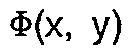

wobei vorausgesetzt ist, daß der Strahlteiler (S) nur eine einzige reflektierende Fläche aufweist.The wavefront disorder
provided that the beam splitter (S) has only a single reflecting surface.
In den Fig. 1b und 1c ist im Prinzip dasselbe Michelson-Interferometer dargestellt, wie in der Fig. 1a. Deshalb sind auch identische Komponenten mit identischen Bezugszeichen wie in der Fig. 1a versehen. Im Unterschied zu der Fig. 1a sind in den Fig. 1b und 1c zwei zu prüfende Planflächen (A, B) unter verschiedenen Inzidenzwinkeln (α. β) hintereinander im Meßstrahlengang (M) des Interferometers angeordnet. In der Fig. 1b wird der Meßstrahlengang (M) zunächst unter dem Winkel (α) an der ersten Planfläche (A) und anschließend unter dem Winkel (β) an der zweiten Planfläche (B) reflektiert. Anschließend wird der Meßstrahlengang (M) am Interferometerspiegel (H) in sich selbst zurückreflektiert. Der Meßstrahlengang (M) hat in den Fig. 1b und 1c dieselbe Länge wie der Meßstrahlengang (M) in Fig. 1a.In principle, the same Michelson interferometer is shown in FIGS. 1b and 1c as in FIG. 1a. For this reason, identical components are provided with identical reference numerals as in FIG. 1a. In contrast to FIG. 1a, two plane surfaces (A, B) to be tested are arranged one behind the other in the measuring beam path (M) of the interferometer at different incidence angles (α, β) in FIGS. 1b and 1c. In Fig. 1b, the measuring beam path (M) is first reflected at the angle (α) on the first plane surface (A) and then at the angle (β) on the second plane surface (B). The measuring beam path (M) is then reflected back into itself at the interferometer mirror (H). The measuring beam path (M) in FIGS. 1b and 1c has the same length as the measuring beam path (M) in FIG. 1a.
In der Fig. 1c sind die beiden Planflächen (A, B) gegenüber der Fig. 1b so verdreht angeordnet, daß der Meßstrahlengang an der ersten Planfläche (A) unter dem Winkel (β) und an der zweiten Planfläche (B) unter dem Winkel (α) reflektiert wird.In Fig. 1c, the two plane surfaces (A, B) are arranged rotated relative to Fig. 1b so that the measuring beam path on the first plane surface (A) at the angle (β) and on the second plane surface (B) at the angle (α) is reflected.
Den beiden Planflächen (A, B) sind nun ebenfalls jeweils ein rechtshändiges Koordinatensystem (xA, yA, zA) bzw. (xB, yB, zB) zugeordnet, deren z-Achsen (zA, zB) senkrecht zur jeweiligen Planfläche und deren x-Achsen (xA, xB) in der Zeichenebene parallel zur jeweiligen Planfläche (A, B) liegen.A right-handed coordinate system (x A , y A , z A ) or (x B , y B , z B ), whose z axes (z A , z B ) are now also assigned to the two plane surfaces (A, B ). perpendicular to the respective flat surface and its x-axes (x A , x B ) in the drawing plane parallel to the respective flat surface (A, B).
Da gleichzeitig zwei Planflächen (A, B) im Meßstrahlengang eingefügt sind, sind die Interferometerspiegel (H, I) genauso orientiert wie in Fig. 1a. Ein Spiegelungsproblem tritt deshalb nicht auf.Since two plane surfaces (A, B) are simultaneously inserted in the measuring beam path, the interferometer mirrors (H, I) are oriented in exactly the same way as in FIG. 1a. There is therefore no problem of mirroring.
In diesen Anordnungen werden nun weitere Interferogramme von dem Kamerasensor (K) aufgezeichnet. Es ist klar, daß die beiden Planflächen (A, B) weitere Beiträge 


wobei berücksichtigt ist, daß die Positionen an denen ein Lichtstrahl an den Planflächen (A, B) reflektiert wird, vom jeweiligen Einfallswinkel (α, β) abhängen. Die Wellenfrontstörungen ΦA, ΦB der beiden Planflächen (A, B) beschreiben die Wellenfrontstörungen, die die jeweilige Planfläche bei senkrechter Inzidenz verursachen würde. Durch die Inzidenzwinkel (α, β) ergeben sich jeweils um den Faktor cos α, bzw. cos β kleinere Beiträge. Die Faktoren 2 in Gleichung (2) berücksichtigen die zweimalige Reflexion an jeder der beiden Planflächen (A, B).In these arrangements, further interferograms are now recorded by the camera sensor (K). It is clear that the two plan areas (A, B) make further contributions
taking into account that the positions at which a light beam is reflected on the plane surfaces (A, B) depend on the respective angle of incidence (α, β). The wavefront disturbances Φ A , Φ B of the two flat surfaces (A, B) describe the wavefront disturbances that the respective flat surface would cause with a vertical incidence. The incidence angles (α, β) each result in smaller contributions by the factor cos α or cos β. The
Zwei weitere Interferogramme werden aufgenommen, nachdem die erste Planfläche (A) Jeweils um eine Strecke xA, die einem ganzzahligen Vielfachen des Pixelabstandes auf der ersten Planfläche (A) in xA-Richtung entspricht, in positive xA-Richtung (Pfeil Pb₂) bzw. in negative xA-Richtung (Pfeil Pb₃) verschoben worden ist. Die dabei gemessenen gesamten Wellenfrontstörungen sind:

nach Verschiebung in Richtung des Pfeiles (Pb2) und

nach Verschiebung der Planfläche (A) in Richtung des Pfeiles (Pb₃).Two more interferograms are recorded after the first plane surface (A) by a distance x A , which corresponds to an integer multiple of the pixel spacing on the first plane surface (A) in the x A direction, in the positive x A direction (arrow Pb₂) or has been moved in the negative x A direction (arrow Pb₃). The total wavefront disturbances measured are:
after shifting in the direction of the arrow (P b2 ) and
after shifting the plane surface (A) in the direction of the arrow (Pb₃).
In der Anordnung gemäß Fig. 1c werden drei weitere Interferogramme mit dem Kamerasensor (K) aufgenommen und mit dem Rechner (R) ausgewertet. Jedoch wird diesmal die zweite Planfläche (B) entlang ihrer xB-Achse zwischen den Aufzeichnungen um eine Strecke xB, das einem ganzzahligen Vielfachen des Pixelabstandes auf der zweiten Planfläche (B) in xB-Richtung entspricht, verschoben.In the arrangement according to FIG. 1c, three further interferograms are recorded with the camera sensor (K) and evaluated with the computer (R). However, this time the second plane surface (B) is shifted along its x B axis between the recordings by a distance x B , which corresponds to an integer multiple of the pixel spacing on the second plane surface (B) in the x B direction.
Die gemessenen Wellenfrontstörungen in der Ebene des Kamerasensors (K) ergeben sich entsprechend unter Berücksichtigung der nun vertauschten Einfallswinkel:

für den unverschobenen Fall,
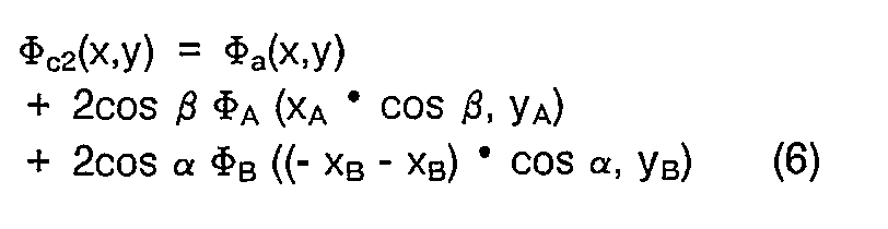
nach Verschiebung in Richtung des Pfeiles (Pc2) (+ xB-Richtung) und

nach Verschiebung in Richtung des Pfeiles (Pc3) (- xB-Richtung)The measured wavefront disturbances in the plane of the camera sensor (K) result accordingly taking into account the now reversed angle of incidence:
for the unmoved case,
after shifting in the direction of the arrow (P c2 ) (+ x B direction) and
after shifting in the direction of the arrow (P c3 ) (- x B direction)
Die weitere Auswertung erfolgt durch Auflösung dieses Gleichungssystems nach den Beiträgen ΦA und ΦB der Wellenfrontstörungen der beiden Planflächen (A, B). Diese Auswertung vereinfacht sich durch die Wahl der Einfallswinkel (α, β). Sie sind so gewählt, daß cos α = 2 cos β ist. Das diskrete Pixelraster des Kamerasensors (K) wird dadurch auf diskrete Pixelraster auf den Planflächen (A, B) abgebildet, die auf beiden Planflächen und während aller Verfahrensschritte identisch sind. Dies läßt sich anschaulich anhand der Detaildarstellungen in den Fig. 1d und 1e erläutern, in denen exemplarisch fünf diskrete Pixel (K₋₂) bis (K₂) des Kamerasensors (K) in x-Richtung betrachtet werden. Wie in der Fig. 1d dargestellt, werden durch die Strahlen (M₋₂, M₋₁, M₀, M₁, M₂) die geradzahligen Pixel (B₄, B₂, B₀, B₋₂, B₋₄) der zweiten Planfläche (B) über die zentralen Pixel (A₋₂, A₋₁, A₀, A₁, A₂) der ersten Planfläche (A) Pixel für Pixel auf die Pixel (K₋₂, K₋₁, K₀, K₁, K₂) des Kamerasensors (K) abgebildet.The further evaluation takes place by solving this system of equations according to the contributions Φ A and Φ B of the wavefront disturbances of the two plane surfaces (A, B). This evaluation is simplified by the choice of the angles of incidence (α, β). They are chosen so that cos α = 2 cos β. The discrete pixel grid of the camera sensor (K) is thus mapped onto discrete pixel grids on the plane surfaces (A, B), which are identical on both plane surfaces and during all process steps. This can be illustrated clearly with the help of the detailed representations in FIGS. 1d and 1e, in which five discrete pixels (K₋₂) to (K₂) of the camera sensor (K) are considered in the x direction. As shown in Fig. 1d, by the rays (M₋₂, M₋₁, M₀, M₁, M₂) the even pixels (B₄, B₂, B₀, B₋₂, B₋₄) of the second plane surface (B ) over the central pixels (A₋₂, A₋₁, A₀, A₁, A₂) of the first plane surface (A) pixel by pixel onto the pixels (K₋₂, K₋₁, K₀, K₁, K₂) of the camera sensor ( K) shown.
Nach der Verschiebung der ersten Planfläche (A) um zwei Pixel, welches der Hälfte des in xA-Richtung auf dieser Planfläche (A) ausgeleuchteten Bereiches entspricht, in Richtung des Pfeiles (Pb₂) werden jeweils Pixel dieser Planfläche (A) mit einem um die Zahl 2 kleineren Index, d.h. die Pixel (A₋₄, A₋₃, A₋₂, A₋₁, A₀), auf die geradzahligen Pixel (B₄, B₂, B₀, B₋₂, B₋₄) der zweiten Planfläche (B) und auf die Pixel (K₋₂ - K₂) des Kamerasensors (K) abgebildet. Entsprechend werden nach der Verschiebung der ersten Planfläche (A) um zwei Pixel in Richtung des Pfeiles (Pb₃) jeweils Pixel der ersten Planfläche (A) mit einem um die Zahl 2 größeren Index, d.h. die Pixel (A₀, A₁, A₂, A₃, A₄), auf dieselben geradzahligen Pixel (B₄, B₂, B₀, B₋₂, B₋₄) der zweiten Planfläche (B) und auf die Pixel (K₋₂ - K₂) des Kamerasensors (K) abgebildet.After shifting the first plane surface (A) by two Pixels, which corresponds to half of the area illuminated in x A direction on this plane surface (A), in the direction of the arrow (Pb₂), pixels of this plane surface (A) are each with an index that is smaller by the
In der Fig. le ist die Abbildung der Pixel (K₋₂, K₋₁, K₀, K₁, K₂) des Kamerasensors (K) dargestellt, wenn die Einfallswinkel (α, β) der beiden Planflächen (A, B) gegeneinander vertauscht sind. Es werden dann nur die geradzahligen Pixel (A₋₄, A₋₂, A₀, A₂, A₄) der ersten Planfläche (A) abgebildet.In Fig. Le, the image of the pixels (K₋₂, K₋₁, K₀, K₁, K₂) of the camera sensor (K) is shown when the angle of incidence (α, β) of the two plane surfaces (A, B) interchanged are. Then only the even-numbered pixels (A₋₄, A₋₂, A₀, A₂, A₄) of the first plane surface (A) are shown.
Wesentlich ist, daß den beiden Planflächen (A, B) ein eindeutiges, diskretes Pixelraster (A₋₄ - A₄) bzw. (B₋₄ - B₄) zugeordnet werden kann, und daß bei der Aufnahme der Interferogramme stets Punkte dieser Pixelraster aufeinander und auf die Pixel (K₋₂ - K₂) des Kamersensors (K) abgebildet werden. Eine Interpolation zwischen den Pixeln ist nicht nötig.It is essential that the two planar surfaces (A, B) can be assigned a clear, discrete pixel grid (A₋₄ - A₄) or (B₋₄ - B₄), and that when recording the interferograms, points of these pixel grids are always on top of each other and be imaged on the pixels (K₋₂ - K₂) of the camera sensor (K). An interpolation between the pixels is not necessary.
Das aus den oben angegebenen sieben Gleichungen (Gleichung (1) - (7)) bestehende Gleichungssystem kann in der Form
geschrieben werden. Die Fehlermatrix (F) ist dann eine Matrix mit 4 m -2 Spalten und 6 m Zeilen, wobei m die Anzahl der Pixel des Kamerasensors (K) in x-Richtung ist. In dem Vektor


für die m-Pixel des Kamerasensors (K) in x-Richtung, (insgesamt also 6 m Werte) aufgelistet. Die Werte der Vektoren

to be written. The error matrix (F) is then a matrix with 4 m -2 columns and 6 m rows, where m is the number of Pixel of the camera sensor (K) in the x direction. In the vector
for the m-pixels of the camera sensor (K) in the x-direction, (total 6 m values). The values of the vectors
Das lineare Gleichungssystem (8) ist dann für jede Spalte des Kamerasensors (K) in y-Richtung zu lösen. Bei einer handelsüblichen CCD-Kamera mit 512 x 512 Pixeln muß das Gleichungssystem 512 mal gelöst werden. Die Fehlermatrix (F) ist jedoch unabhängig von x und y und deshalb eine Konstante. Die einzelnen Koeffizienten von (F) sind entweder 0, cos α oder cos β.The linear system of equations (8) is then to be solved for each column of the camera sensor (K) in the y direction. With a commercially available CCD camera with 512 x 512 pixels, the system of equations must be solved 512 times. However, the error matrix (F) is independent of x and y and is therefore a constant. The individual coefficients of (F) are either 0, cos α or cos β.
Durch Multiplikation des Gleichungssystems (8) mit der transponierten Fehlermatrix (FT) und der zu (FTF) inversen Matrix (FTF)⁻¹ ergibt sich als Lösung

mit der Gewichtsmatrix (G).By multiplying the equation system (8) with the transposed error matrix (F T) and the results for (F T F) inverse matrix (F T F) ⁻¹ as a solution
with the weight matrix (G).
Die konstante Gewichtsmatrix (G) ist in dem Rechner (R) abgespeichert, wodurch eine schnelle Berechnung der Wellenfrontstörungen 
Aus den Wellenfrontstörungen 

bei Kenntnis der Wellenlänge λ des Lasers (L) berechnen.From the wavefront interference
calculate with knowledge of the wavelength λ of the laser (L).
Entsprechendes gilt auch für die Abweichungen 
Die Quadratwurzel aus der Quadratsumme der Koeffizienten einer Zeile der Gewichtsmatrix (G) ist ein Maß für die statistische Unsicherheit, mit der die Wellenfrontstörungen (ΦA) und (ΦB) ermittelt werden. Da die Gewichtsmatrix (G) für alle Spalten des Kamerasensors (K) in y-Richtung gleich ist, ist auch die statistische Unsicherheit unabhängig vom jeweiligen y-Wert. Es läßt sich zeigen, daß die statistische Unsicherheit in der Mitte der ersten Planflächen (A) nur geringfügig größer als die Unsicherheit ist, mit der die gesamten Wellenfrontstörungen (Φa1, Φb1, Φb2, Φb3, Φc1, Φc2, Φc3) in der Mitte der ersten Planflächen (A) behaftet sind. Am Rand des Meßbereiches in ± xA-Richtung steigt diese Unsicherheit zwar etwas an. Es läßt sich zeigen, daß die wesentlichen statistischen Fehler, durch die Unsicherheiten hervorgerufen werden, mit denen die Wellenfrontstörung Φa des leeren Interferometers behaftet sind. Durch mehrfache Messung der Wellenfrontstörung Φa lassen sich diese Fehler erheblich herabsetzen.The square root of the square sum of the coefficients of a row of the weight matrix (G) is a measure of the statistical uncertainty with which the wavefront disturbances (Φ A ) and (Φ B ) are determined. Since the weight matrix (G) is the same for all columns of the camera sensor (K) in the y direction, the statistical uncertainty is also independent of the respective y value. It can be shown that the statistical uncertainty in the middle of the first plane surfaces (A) is only slightly larger than the uncertainty with which the entire wavefront disturbances (Φ a1 , Φ b1 , Φ b2 , Φ b3 , Φ c1 , Φ c2 , Φ c3 ) in the middle of the first plane surfaces (A). This uncertainty increases somewhat at the edge of the measuring range in the ± x A direction. It can be shown that the essential statistical errors, caused by the uncertainties with which the wavefront disturbance Φ a of the empty interferometer are afflicted. By repeatedly measuring the wavefront interference Φ a , these errors can be significantly reduced.
Es ist klar, daß aufgrund der symmetrischen Anordnung dies für die erste Planfläche (A) und die zweite Planfläche (B) gleichermaßen gilt.It is clear that due to the symmetrical arrangement, this applies equally to the first plane surface (A) and the second plane surface (B).
Für jede Spalte des Kamerasensors (K) in y-Richtung werden anhand des oben angegebenen Gleichungssystems (8) 4 m -2 Unbekannte für die Wellenfrontstörungen beider Planflächen (A, B) berechnet. Dafür stehen insgesamt 6 m-Gleichungen zur Verfügung, d.h. das Gleichunassystem ist überbestimmt. Andererseits ist bei der bisherigen Lösung auch eine evtl. Kippung der Planflächen (A, B) bei den Verschiebungen noch nicht berücksichtigt. Solche Kippungen würden jedoch zu fehlerhaften Meßergebnissen führen. Deshalb wird die gleiche Auswertung noch einmal durchgeführt, jedoch werden jetzt nur die Wellenfrontstörungen ΔΦb2, ΔΦb3, ΔΦc2, ΔΦc3 zur Auswertung herangezogen. Liefert diese zweite Auswertung andere Wellenfrontstörungen ΦA2 (xA, yA) oder ΦB2 (xB, yB) so haben Kippungen oder Längenänderungen des Meßstrahlenganges (M) stattgefunden. Diese lassen sich aus den Differenzen 


In der Fig. 2 ist ein zweites Ausführungsbeispiel zur Absolutprüfung von Planflächen dargestellt, das im wesentlichen aus einem Fizeau-Interferometer besteht. Die meisten Komponenten in diesem Ausführungsbeispiel entsprechen denen aus den Fig. 1a bis 1e. Sie sind deshalb mit den gleichen Bezugszeichen mit einem Index 6 versehen.2 shows a second exemplary embodiment for the absolute test of plane surfaces, which essentially consists of a Fizeau interferometer. Most of the components in this exemplary embodiment correspond to those from FIGS. 1a to 1e. They are therefore provided with the same reference numerals with an index 6.
Im Unterschied zum Michelson-Interferometer haben der Meßstrahlengang und der Referenzstrahlengang in einem Fizeau-Interferometer einen gemeinsamen Bereich (G₆). Der Interferometerspiegel des Referenzstrahlenganges (I₆) ist teildurchlässig und keilförmig. Vor dem Kamerasensor (K₆) ist noch ein Raumfrequenzfilter (F₆) angeordnet. Das an der Vorderfläche (I6V) des Interferometerspiegels (I₆) reflektierte Licht wird dadurch herausgefiltert.In contrast to the Michelson interferometer, the measuring beam path and the reference beam path in a Fizeau interferometer have a common area (G₆). The interferometer mirror of the reference beam path (I₆) is partially permeable and wedge-shaped. A spatial frequency filter (F₆) is arranged in front of the camera sensor (K₆). The light reflected on the front surface (I 6V ) of the interferometer mirror (I₆) is filtered out.
Das Meßverfahren ist analog zu dem bei der Beschreibung der Fig. 1a bis 1e beschriebenen. Die Topographie der Planflächen (A₆, B₆) kann nach der Planprüfung und nach der Auswertung durch den Rechner (R₆) auf einem Monitor (MO₆) graphisch dargestellt werden.The measuring method is analogous to that described in the description of FIGS. 1a to 1e. The topography of the plan areas (A₆, B₆) can be graphically displayed on a monitor (MO₆) after the plan check and after evaluation by the computer (R₆).
In der Darstellung nach Fig. 2 ist die erste Planfläche (A₆) unter dem Inzidenzwinkel (α₆) und die zweite Planfläche (B₆) unter dem Inzidenzwinkel (β₆) im Meßstrahlengang (M₆) angeordnet. Sowohl diese beiden Planflächen (A₆, B₆) als auch der Interferometerspiegel (H₆) sind auf Spiegelhalter (PA, PB, PH) befestigt.2, the first plane surface (A₆) is arranged at the angle of incidence (α₆) and the second plane surface (B₆) at the angle of incidence (β₆) in the measuring beam path (M₆). Both these two flat surfaces (A₆, B₆) and the interferometer mirror (H₆) are attached to mirror holders (P A , P B , P H ).
Auf der Basisplatte (Bp₆) sind t-förmige Schienen (J₆₁, J₆₂, J₆₃, J₆₄) angeordnet. die Jeweils mit Nuten (N₆₁, N₆₂, N₆₃, N₆₄) versehen sind. In diese Nuten (N₆₁ - N₆₄) können nicht dargestellte Kugeln an der Unterseite der Spiegelhalter (PA, PB, PH) eingreifen. wodurch eine Dreipunktlagerung bewirkt wird.On the base plate (Bp₆) T-shaped rails (J₆₁, J₆₂, J₆₃, J₆₄) are arranged. which are each provided with grooves (N₆₁, N₆₂, N₆₃, N₆₄). In these grooves (N₆₁ - N₆₄) balls, not shown, can engage on the underside of the mirror holder (P A , P B , P H ). which causes a three-point bearing.
Entsprechende Schienen sind auch unter den Spiegelhaltern (PA, PB, PH) in den dargestellten Positionen vorgesehen, jedoch werden sie durch die Spiegelhalter (PA, PB, PH) verdeckt und sind deshalb nicht dargestellt.Corresponding rails are also provided under the mirror holders (P A , P B , P H ) in the positions shown, but they are covered by the mirror holders (P A , P B , P H ) and are therefore not shown.
Zum gegenseitigen Vertauschen der Inzidenzwinkel (α₆, β₆) beider Planflächen (A₆, B₆) wird der Spiegelhalter (PA) der die erste Planfläche (A₆) trägt, auf die Schiene (J₆₁) und der Spiegelhalter (PB), der die zweite Planfläche (B₆) trägt, auf die Schiene (J₆₄) gesetzt. Der den Interferometerspiegel (H₆) tragende Spiegelhalter (PH) wird auf die Schiene (J₆₃) gesetzt.To mutually interchange the incidence angle (α₆, β₆) of both flat surfaces (A₆, B₆) the mirror holder (P A ) which carries the first flat surface (A₆) on the rail (J₆₁) and the mirror holder (P B ), the second Flat surface (B₆) carries, placed on the rail (J₆₄). The interferometer mirror (H₆) carrying mirror holder (P H ) is placed on the rail (J₆₃).
Zur Messung der Wellenfrontstörung des leeren Interferometers werden die beiden Planflächen (A₆, B₆) aus dem Meßstrahlengang des Interferometers entfernt und der Interferometerspiegel (H₆) auf die Schiene (J₆₂) gesetzt.To measure the wavefront interference of the empty interferometer, the two flat surfaces (A₆, B₆) are removed from the measuring beam path of the interferometer and the interferometer mirror (H₆) is placed on the rail (J₆₂).
Die Spiegelhalter (PA, PB) der beiden Planflächen (A₆, B₆) sind Jeweils mit einer µm-Schraube (MA, MB) versehen, die eine Verschiebung der beiden Planflächen (A₆, B₆) in der Zeichenebene und parallel zur Jeweiligen Planfläche (A₆, B₆) ermöglicht.The mirror holders (P A , P B ) of the two flat surfaces (A₆, B₆) are each provided with a µm screw (M A , M B ), which shifts the two flat surfaces (A₆, B₆) in the plane of the drawing and parallel to it Respective plane surface (A₆, B₆) enables.
Nachdem die beiden Planflächen (A₆, B₆) absolut geprüft sind, kann das Interferometer dadurch kalibriert werden, daß eine der beiden Planflächen (A₆, B₆) anstelle des Interferometerspiegels (H₆) in das Interferometer eingesetzt wird. Dabei tritt beim Fizeau-Interferometer jedoch das Problem auf, daß die zu prüfenden Planflächen (A₆, B₆) einerseits einen möglichst großen Reflexionskoeffizienten haben sollten, damit kontrastreiche Interferogramme aufgenommen werden können. Andererseits sollte aus demselben Grund der Interferometerspiegel (H₆) nur einen kleinen Reflexionskoeffizienten haben.After the two flat surfaces (A₆, B₆) have been absolutely checked, the interferometer can be calibrated by inserting one of the two flat surfaces (A₆, B₆) into the interferometer instead of the interferometer mirror (H₆). The problem with the Fizeau interferometer, however, is that the plane surfaces to be tested (A₆, B₆) should on the one hand have the largest possible reflection coefficient so that high-contrast interferograms can be recorded. On the other hand, for the same reason, the interferometer mirror (H₆) should only have a small reflection coefficient.
Dieses Problem ist jedoch dadurch lösbar, daß die zweite Planfläche (B₆) eine Teilung aus abwechselnd opaken und reflektierenden Streifen aufweist. Die reflektierenden Streifen sollten breiter als die opaken Streifen sein. Die Planfläche (B₆) wird dann zur Absolutprüfung in 0.-Beugungsordnung untersucht. Sie weist dann einen großen Reflexionskoeffizienten auf. Zur Kalibrierung des Interferometers wird sie dann so geschwenkt anstelle des Interferometerspiegels (H₆) im Interferometer angeordnet, daß das in die ± 1.-Beugungsordnung reflektierte Licht den Raumfrequenzfilter (F₆) transmittiert. Der Reflexionskoeffizient der ± 1.-Beugungsordnung ist erheblich geringer, als der Reflexionskoeffizient der 0.-Beugungsordnung.However, this problem can be solved in that the second plane surface (B₆) has a division of alternating opaque and reflective strips. The reflective stripes should be wider than the opaque stripes. The plane surface (B₆) is then examined for absolute testing in the 0th diffraction order. It then has a large reflection coefficient. To calibrate the interferometer, it is then pivoted in place of the interferometer mirror (H₆) in the interferometer so that the light reflected in the ± 1st diffraction order transmits the spatial frequency filter (F₆). The reflection coefficient of the ± 1st diffraction order is considerably lower than the reflection coefficient of the 0 diffraction order.
Wellenfrontstörungen, die durch Teilungsfehler verursacht werden, können dadurch eliminiert werden, daß eine erste Messung in der + 1.-Beugungsordnung und eine zweite Messung in der - 1.-Beugungsordnung durchgeführt wird.Wavefront interference caused by pitch errors can be eliminated by taking a first measurement in the + 1st diffraction order and a second measurement in the - 1st diffraction order.
In den Fig. 1a - 1c und in Fig. 2 sind die Strahlengänge so dargestellt, daß für beide Planflächen (A, B, A₆, B₆) symmetrische Prüfbedingungen vorliegen. Für den Fall, daß keine symmetrischen Prüfbedingungen erwünscht sind, kann der Interferometerspiegel (H, H₆) möglichst nahe bei der zweiten Planfläche (B, B₆) angeordnet sein. Durch ein Fernrohr, das zwischen dem Strahlteiler (S, S₆) und dem Kamerasensor (K, K₆) vorzusehen ist, kann die zweite Planfläche (B, B₆) auf den Kamerasensor (K, K₆) abgebildet werden, so daß diese zweite Planfläche (B, B₆) mit größerer Genauigkeit geprüft werden kann.1a - 1c and in FIG. 2, the beam paths are shown in such a way that symmetrical test conditions are present for both plane surfaces (A, B, A₆, B₆). In the event that no symmetrical test conditions are desired, the interferometer mirror (H, H₆) can be arranged as close as possible to the second plane surface (B, B₆). The second plane surface (B, B₆) can be imaged on the camera sensor (K, K₆) by means of a telescope which is to be provided between the beam splitter (S, S₆) and the camera sensor (K, K₆), so that this second plane surface ( B, B₆) can be checked with greater accuracy.
Claims (12)
Applications Claiming Priority (2)
| Application Number | Priority Date | Filing Date | Title |
|---|---|---|---|
| DE4003100A DE4003100A1 (en) | 1990-02-02 | 1990-02-02 | METHOD AND DEVICE FOR INTERFEROMETRIC ABSOLUTE TESTING OF SURFACES |
| DE4003100 | 1990-02-02 |
Publications (3)
| Publication Number | Publication Date |
|---|---|
| EP0441153A2 true EP0441153A2 (en) | 1991-08-14 |
| EP0441153A3 EP0441153A3 (en) | 1991-10-23 |
| EP0441153B1 EP0441153B1 (en) | 1994-05-25 |
Family
ID=6399294
Family Applications (1)
| Application Number | Title | Priority Date | Filing Date |
|---|---|---|---|
| EP91100644A Expired - Lifetime EP0441153B1 (en) | 1990-02-02 | 1991-01-19 | Procedure and device for absolute interferometric testing of flat surfaces |
Country Status (4)
| Country | Link |
|---|---|
| US (1) | US5106194A (en) |
| EP (1) | EP0441153B1 (en) |
| JP (1) | JP3004369B2 (en) |
| DE (2) | DE4003100A1 (en) |
Families Citing this family (6)
| Publication number | Priority date | Publication date | Assignee | Title |
|---|---|---|---|---|
| DE4204857C2 (en) * | 1991-02-18 | 1998-01-22 | Asahi Optical Co Ltd | Method for examining a surface shape with an interferometer |
| CH693968A5 (en) * | 1993-04-21 | 2004-05-14 | Fraunhofer Ges Forschung | Method and apparatus for the Topographiepruefung of surfaces. |
| JP3183046B2 (en) * | 1994-06-06 | 2001-07-03 | キヤノン株式会社 | Foreign particle inspection apparatus and method for manufacturing semiconductor device using the same |
| US6249351B1 (en) | 1999-06-03 | 2001-06-19 | Zygo Corporation | Grazing incidence interferometer and method |
| US6184994B1 (en) | 1999-10-20 | 2001-02-06 | Ade Phase Shift Technology | Method and apparatus for absolutely measuring flat and sperical surfaces with high spatal resolution |
| JP5802369B2 (en) | 2010-07-29 | 2015-10-28 | 富士フイルム株式会社 | Actinic ray-sensitive or radiation-sensitive resin composition, and resist film and pattern forming method using the same |
Family Cites Families (2)
| Publication number | Priority date | Publication date | Assignee | Title |
|---|---|---|---|---|
| DD219565A1 (en) * | 1983-12-05 | 1985-03-06 | Adw Ddr | ARRANGEMENT FOR INTERFEROMETIC QUALITY TESTING OF TECHNICAL SURFACES |
| JPS60209106A (en) * | 1984-03-31 | 1985-10-21 | Konishiroku Photo Ind Co Ltd | Flatness inspecting device |
-
1990
- 1990-02-02 DE DE4003100A patent/DE4003100A1/en not_active Withdrawn
-
1991
- 1991-01-19 DE DE59101691T patent/DE59101691D1/en not_active Expired - Fee Related
- 1991-01-19 EP EP91100644A patent/EP0441153B1/en not_active Expired - Lifetime
- 1991-01-31 US US07/648,199 patent/US5106194A/en not_active Expired - Lifetime
- 1991-02-01 JP JP3012190A patent/JP3004369B2/en not_active Expired - Fee Related
Also Published As
| Publication number | Publication date |
|---|---|
| DE59101691D1 (en) | 1994-06-30 |
| DE4003100A1 (en) | 1991-08-08 |
| JPH051909A (en) | 1993-01-08 |
| US5106194A (en) | 1992-04-21 |
| EP0441153A3 (en) | 1991-10-23 |
| JP3004369B2 (en) | 2000-01-31 |
| EP0441153B1 (en) | 1994-05-25 |
Similar Documents
| Publication | Publication Date | Title |
|---|---|---|
| EP0370229B1 (en) | Interferometric process for testing optical elements producing aspherical wave fronts | |
| DE10195052B3 (en) | Method and devices for determining a geometric property of a test object and optical profile measuring system | |
| DE4204857C2 (en) | Method for examining a surface shape with an interferometer | |
| DE69516136T2 (en) | METHOD FOR MEASURING THE TOPOGRAPHY OF A SURFACE WITH AN INTERFEROMETER WITH PHASE SHIFT | |
| DE3318678A1 (en) | METHOD AND DEVICE FOR INTERFEROMETRY OF RAUER SURFACES | |
| DE4124223C2 (en) | Procedure for evaluating interferograms and interferometers | |
| DE3888831T2 (en) | OPTICAL APPARATUS FOR USE WITH INTERFEROMETRIC MEASURING DEVICES. | |
| WO2008012091A2 (en) | Method and apparatus for determining a deviation of an actual shape from a desired shape of an optical surface | |
| EP0561015A1 (en) | Interferometric phase-measuring | |
| EP0453977B1 (en) | Method and process for optical inspection of test objects | |
| DE10202738B4 (en) | Phase shift strip analysis method and apparatus using this method | |
| EP0441153B1 (en) | Procedure and device for absolute interferometric testing of flat surfaces | |
| EP3571464B1 (en) | Device and method for calibrating a measuring apparatus by means of projected patterns using a virtual plane | |
| DE1912162C3 (en) | Method for obtaining interference fringes in a double-exposed hologram interferometer | |
| DE2447889A1 (en) | INTERFEROMETER FOR MEASURING WAVE FRONT SECTIONS OF GENERAL IMAGING SYSTEMS, IN PARTICULAR OF THE HUMAN EYE | |
| DE2636498C2 (en) | Method for interferometric surface brass | |
| EP3571465B1 (en) | Device and method for calibrating a measuring apparatus by means of projected patterns | |
| DE102021211799A1 (en) | Method and measuring system for interferometric determination of a local distribution of an optical property of a test object | |
| DE19828815A1 (en) | Laser interferometer for two-axis position measurement of moving machine components | |
| DE4206151C2 (en) | Device for observing a test specimen surface for measuring deformation using the speckle shearing method | |
| DE102020102959A1 (en) | Surface measuring system for measuring a surface of a test object | |
| DE19720122C2 (en) | Method for determining an optical, mechanical, electrical or other measured variable | |
| CH683561A5 (en) | Grating interferometer with at least two successive diffraction gratings. | |
| DE3616245A1 (en) | Interferometer system for length and angle measurement | |
| DE2547620A1 (en) | Multiple reflection unit for angle measurement - is for determination of plane of rotation of test piece and relates to goniometers, theodolites etc. |
Legal Events
| Date | Code | Title | Description |
|---|---|---|---|
| PUAI | Public reference made under article 153(3) epc to a published international application that has entered the european phase |
Free format text: ORIGINAL CODE: 0009012 |
|
| AK | Designated contracting states |
Kind code of ref document: A2 Designated state(s): CH DE FR GB LI NL SE |
|
| PUAL | Search report despatched |
Free format text: ORIGINAL CODE: 0009013 |
|
| AK | Designated contracting states |
Kind code of ref document: A3 Designated state(s): CH DE FR GB LI NL SE |
|
| 17P | Request for examination filed |
Effective date: 19920317 |
|
| 17Q | First examination report despatched |
Effective date: 19930709 |
|
| GRAA | (expected) grant |
Free format text: ORIGINAL CODE: 0009210 |
|
| AK | Designated contracting states |
Kind code of ref document: B1 Designated state(s): CH DE FR GB LI NL SE |
|
| REF | Corresponds to: |
Ref document number: 59101691 Country of ref document: DE Date of ref document: 19940630 |
|
| GBT | Gb: translation of ep patent filed (gb section 77(6)(a)/1977) |
Effective date: 19940817 |
|
| ET | Fr: translation filed | ||
| EAL | Se: european patent in force in sweden |
Ref document number: 91100644.3 |
|
| PLBE | No opposition filed within time limit |
Free format text: ORIGINAL CODE: 0009261 |
|
| STAA | Information on the status of an ep patent application or granted ep patent |
Free format text: STATUS: NO OPPOSITION FILED WITHIN TIME LIMIT |
|
| 26N | No opposition filed | ||
| REG | Reference to a national code |
Ref country code: GB Ref legal event code: IF02 |
|
| PGFP | Annual fee paid to national office [announced via postgrant information from national office to epo] |
Ref country code: DE Payment date: 20090122 Year of fee payment: 19 Ref country code: NL Payment date: 20090114 Year of fee payment: 19 |
|
| PGFP | Annual fee paid to national office [announced via postgrant information from national office to epo] |
Ref country code: CH Payment date: 20090115 Year of fee payment: 19 Ref country code: GB Payment date: 20090122 Year of fee payment: 19 |
|
| PGFP | Annual fee paid to national office [announced via postgrant information from national office to epo] |
Ref country code: SE Payment date: 20090114 Year of fee payment: 19 |
|
| PGFP | Annual fee paid to national office [announced via postgrant information from national office to epo] |
Ref country code: FR Payment date: 20090115 Year of fee payment: 19 |
|
| REG | Reference to a national code |
Ref country code: NL Ref legal event code: V1 Effective date: 20100801 |
|
| REG | Reference to a national code |
Ref country code: CH Ref legal event code: PL |
|
| GBPC | Gb: european patent ceased through non-payment of renewal fee |
Effective date: 20100119 |
|
| EUG | Se: european patent has lapsed | ||
| REG | Reference to a national code |
Ref country code: FR Ref legal event code: ST Effective date: 20100930 |
|
| PG25 | Lapsed in a contracting state [announced via postgrant information from national office to epo] |
Ref country code: CH Free format text: LAPSE BECAUSE OF NON-PAYMENT OF DUE FEES Effective date: 20100131 Ref country code: NL Free format text: LAPSE BECAUSE OF NON-PAYMENT OF DUE FEES Effective date: 20100801 Ref country code: LI Free format text: LAPSE BECAUSE OF NON-PAYMENT OF DUE FEES Effective date: 20100131 Ref country code: FR Free format text: LAPSE BECAUSE OF NON-PAYMENT OF DUE FEES Effective date: 20100201 |
|
| PG25 | Lapsed in a contracting state [announced via postgrant information from national office to epo] |
Ref country code: DE Free format text: LAPSE BECAUSE OF NON-PAYMENT OF DUE FEES Effective date: 20100803 |
|
| PG25 | Lapsed in a contracting state [announced via postgrant information from national office to epo] |
Ref country code: GB Free format text: LAPSE BECAUSE OF NON-PAYMENT OF DUE FEES Effective date: 20100119 |
|
| PG25 | Lapsed in a contracting state [announced via postgrant information from national office to epo] |
Ref country code: SE Free format text: LAPSE BECAUSE OF NON-PAYMENT OF DUE FEES Effective date: 20100120 |