EP0441204A2 - Dispositif de fentes rayonnantes avec accord par tôle de chicane - Google Patents
Dispositif de fentes rayonnantes avec accord par tôle de chicane Download PDFInfo
- Publication number
- EP0441204A2 EP0441204A2 EP91101001A EP91101001A EP0441204A2 EP 0441204 A2 EP0441204 A2 EP 0441204A2 EP 91101001 A EP91101001 A EP 91101001A EP 91101001 A EP91101001 A EP 91101001A EP 0441204 A2 EP0441204 A2 EP 0441204A2
- Authority
- EP
- European Patent Office
- Prior art keywords
- vanes
- waveguide
- radiating elements
- wave
- column
- Prior art date
- Legal status (The legal status is an assumption and is not a legal conclusion. Google has not performed a legal analysis and makes no representation as to the accuracy of the status listed.)
- Granted
Links
Images
Classifications
-
- H—ELECTRICITY
- H01—ELECTRIC ELEMENTS
- H01Q—ANTENNAS, i.e. RADIO AERIALS
- H01Q21/00—Antenna arrays or systems
- H01Q21/06—Arrays of individually energised antenna units similarly polarised and spaced apart
- H01Q21/061—Two dimensional planar arrays
- H01Q21/064—Two dimensional planar arrays using horn or slot aerials
-
- H—ELECTRICITY
- H01—ELECTRIC ELEMENTS
- H01Q—ANTENNAS, i.e. RADIO AERIALS
- H01Q13/00—Waveguide horns or mouths; Slot antennas; Leaky-waveguide antennas; Equivalent structures causing radiation along the transmission path of a guided wave
-
- H—ELECTRICITY
- H01—ELECTRIC ELEMENTS
- H01Q—ANTENNAS, i.e. RADIO AERIALS
- H01Q21/00—Antenna arrays or systems
- H01Q21/0006—Particular feeding systems
- H01Q21/0037—Particular feeding systems linear waveguide fed arrays
- H01Q21/0043—Slotted waveguides
- H01Q21/005—Slotted waveguides arrays
Definitions
- This invention relates to a line array of colinear slot radiators and, more particularly, to an array of plural parallel columns of slot radiators with excitation and phasing of electromagnetic waves controlled by a set of fin-shaped vanes upstanding from a common broad wall of a waveguide or cavity.
- An array of slot radiators disposed in a staggered line along a wall of a waveguide is employed frequently to generate a beam of electromagnetic power.
- the antenna comprises a waveguide of rectangular cross section wherein the width of a broad wall is double the height of a narrow wall, and wherein the slots are formed through one of the broad walls.
- Antennas are constructed also of a plurality of these slotted waveguides arranged side-by-side to provide a two-dimensional array of slot radiators arranged in rows and columns.
- a column of slot radiators is considered to be oriented in the longitudinal direction, i.
- An antenna composed of a single waveguide generates a fan beam while an antenna composed of a plurality of the waveguides arranged side by side produces a beam having well-defined directivity in both the plane parallel to the columns and the orthogonal plane parallel to the rows.
- Antennas employing slot radiators may have slots which are angled relative to a center line of the broad wall of the waveguide, or may have slots which are arranged parallel to the center line of the broad wall of the waveguide but offset from said center line alternately on one side and the other side.
- the configuration of the antenna of primary interest herein is to be configured with all of the slots being parallel to each other and arranged colinearly in parallel columns. The colinearity eliminates unwanted grating lobes or second order beams.
- a cophasal relationship among the radiations from the various slot radiators is employed for generating a broadside beam directed perpendicularly to a plane containing the plurality of waveguides.
- the antenna comprising the two-dimensional array of rows and columns of radiators is of primary interest.
- One method of obtaining the cophasal relationship is to position the slot radiators with a spacing of one guide wavelength. However, such a spacing is sufficiently large to introduce grating lobes to the directivity pattern of the antenna and, accordingly, it is preferred frequently to employ a smaller spacing, typically one half of the guide wavelength, between successive ones of the slot radiators.
- the spacing of one half guide wavelength introduces a problem because a wave propagating along the waveguide undergoes a phase shift of 180 degrees during propagation through a distance of one-half guide wavelength. Therefore, the requirement of a cophasal relationship is contradicted by the desire to space the radiators at a distance of one-half guide wavelength. Typically, a cophasal result is obtained, despite the half guide wavelength spacing, by alternating the direction of the slot positioning used to achieve slot coupling to the energy in the waveguide.
- the antenna of a single waveguide having broad walls of sufficient width to form multiple columns of slot radiators within a single broad wall. This would eliminate the need for constructing multiple individual waveguides.
- a constriction of multiple columns of slot radiators within a single broad wall introduces a further problem, namely, that consecutive slot radiators within any row of the array would be excited with radiation which differs in phase by 180 degrees. Thus, the cophasal relationship would not be attained.
- an antenna comprising an array of slot radiators disposed in an arrangement of parallel columns and parallel rows. All of the slot radiators are formed within a single top broad wall of a broad waveguide or cavity having rectangular cross section.
- the slots of the radiators are parallel to each other and, in a preferred embodiment of the invention, the longitudinal dimension of each slot is oriented parallel to the columns.
- the waveguide is excited by a transverse electric wave TE n,o wherein n may equal any integer.
- a fin-like resonant vane upstanding from a bottom broad wall of the waveguide. The vanes extend partway from the bottom broad wall towards the top broad wall, but do not contact the top broad wall.
- each of the imaginary waveguides is relatively narrow having an aspect ratio wherein the width of a broad wall is approximately double the height of a sidewall.
- the imaginary waveguides are contiguous to each other, and are separated by virtual sidewalls at which there is a zero value of electric field because of the characteristics of the TE n, 0 mode. All of the vanes are arranged parallel to each other.
- the vanes are disposed at the sites of the slot radiators, are oriented perpendicularly to a center line of the waveguide, and are disposed in alternating fashion relative to a central vertical plane of each imaginary waveguide.
- a vane extends perpendicularly from a virtual sidewall, the extension being a distance of approximately one third of the distance between sidewalls of each imaginary waveguide. Extension of a vane from the bottom broad wall to the top broad wall is approximately 80% of the distance between the two broad walls.
- the slots are spaced apart on centers by one-half guide wavelength.
- each of the imaginary waveguides the alternating positions of the vanes results in a sidewise deflection of the path of propagation of an electromagnetic wave about the central vertical plane of the imaginary waveguide.
- the alternate offsetting of the path of propagation introduces a reversal in the excitation phase at each slot radiator which cancels the alternation of phase associated with the fact that the slots in each column are spaced only one-half waveguide wavelength apart. This results in cophasal excitation of all the slot radiators within a single column.
- the array of vanes of one imaginary waveguide is the mirror image of the array of vanes in the other imaginary waveguide.
- the desired antenna having slot radiators arranged in rows and columns, spaced apart by one-half of the guide wavelength, is achieved with cophasal radiation from all slots.
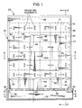
- the antenna 20 comprises a microwave structure having the form of a cavity or broad waveguide 26.
- the waveguide 26 comprises a top broad wall 28, a bottom broad wall 30, a right sidewall 32, a left sidewall 34, a front wall 36, and a back wall 38.
- the broad walls 28 and 30 are disposed parallel to each other, are spaced apart from each other, and are joined together at their peripheral edges by the sidewalls 32 and 34, the front wall 36 and the back wall 38.
- the terms "top” and “bottom” are used for purposes of convenience in relating the description of the antenna to the sectional views of Figs. 2 and 3, and do not imply a preferred orientation to the antenna 20 which may be operated in any desired orientation.
- the terms "right” and “left” are employed to relate the antenna components to the portrayal in Fig. 1, and do not imply any preferred orientation to the antenna 20.
- the broad walls 28 and 30, the sidewalls 32 and 34, the front wall 36 and the back wall 38 are each formed of an electrically conductive material, preferably a metal such as brass or aluminum, which produces a totally enclosed space which may be viewed as a cavity or a waveguide.
- the microwave structure of the antenna will be described as the waveguide 26.
- the waveguide 26 there are two embodiments of the waveguide 26, one embodiment employing a traveling wave and having a termination (as will be described hereinafter) to prevent generation of a reflected wave, and the other embodiment employing a standing wave of varying standing-wave ratio and having a shorting end wall to reflect a wave in the reverse direction.
- Each of the radiating elements is formed as an aperture within the thin top broad wall 28, each aperture being configured as a longitudinal slot 40 having dimensions of length and width, the length of a slot 40 being many times greater than the width of a slot 40.
- the longitudinal dimension of each slot 40 is oriented parallel to the direction of the columns 24.
- the center of each slot 40 is indicated at the center of a square cell defined by the intersecting phantom lines of the rows 22 and the columns 24.
- the portion of the waveguide 26 enclosed within a column has the cross-sectional dimensions of an approximately 2 x 1 (aspect ratio) rectangular waveguide wherein a broad wall has a cross-sectional dimension which is approximately twice the cross-sectional dimension of a sidewall.
- both of the broad walls 28 and 30 are many times greater in cross-sectional dimension than the sidewalls 32 and 34.
- This configuration of the cross-section of the waveguide 26 enables the waveguide 26 to support a higher-order rectangular waveguide mode of transverse electric (TE) electromagnetic wave in which the order of the mode is equal to the number of columns.
- TE transverse electric
- electromagnetic power is to be applied via a higher-order-mode wave launcher 46 located at the front wall 36 for launching a TE6,0 wave which travels within the waveguide 26 from the front wall 36 to the back wall 38 past all of the slots 40.
- the antenna 20 includes a set of vanes 48 which are positioned on the bottom broad wall 30 and located in the cell of each slot 40 to direct the electromagnetic wave within the waveguide 26 to propagate along continuous paths to attain a desired coupling of power from the wave to each slot 40.
- Each vane 48 is formed of a thin sheet of metal upstanding from the bottom broad wall 30 and extending partway towards the top broad wall 28.
- Each of the vanes 48 has a planar shape and is disposed parallel to the front wall 36. Each of the vanes 48 extends transversely from an edge of a column 24 a distance of approximately one-third of the width of the column 24. The locations of the vanes 48 within the respective columns 24 are staggered from one column to the next column such that an array of vanes 48, as viewed in a column of Fig. 1, is the reverse of an array of the vanes 48 as viewed in the next column of Fig. 1. As a result of the reversal of the array of vanes 48 from column to column, the vanes 48 of contiguous columns are shown in Fig. 1 to abut each other to provide vanes having twice the width of the vanes located at the sidewalls 32 and 34.
- Figs. 1 and 3 The wider configuration of vane provided by abutment of vanes of contiguous columns 24 is identified in Figs. 1 and 3 by the legend 48A.
- Fig. 1 a portion of the top broad wall 28 is cut away to show the wider configuration of vane 48A.
- the launcher 46 comprises a waveguide 50 having a rectangular cross section and being formed of the aforementioned front wall 36 which serves as a sidewall of the waveguide 50, and a second sidewall 52 opposite the wall 36.
- the waveguide 50 includes top and bottom broad walls 54 and 56 which are joined by the walls 36 and 52.
- the transverse dimension of each of the broad walls 54 and 56 is approximately double the transverse dimension of each of the walls 36 and 52 to provide an approximately 2 x 1 aspect ratio to a cross section of the waveguide 50.
- Coupling slots 58 are located in the front wall 36, each coupling slot having a linear form with a length and a width, the length being many times greater than the width.
- the coupling slots 58 are oriented with their sides parallel to the broad walls 56 and 58, the coupling slots 58 being located half-way between the broad walls 54 and 56.
- the slots 58 are spaced apart on centers by one-half the guide wavelength in the longitudinal direction along the waveguide 50.
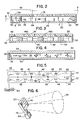
- the waveguide 50 is energized with an electromagnetic wave in the TE1 , 0 mode in which the electric field is perpendicular to the broad walls 54 and 56 as shown in Fig. 2.
- the electric fields coupled through each of the slots 58 induce the aforementioned transverse electric wave in the waveguide 26 with electric field disposed perpendicularly to the broad walls 28 and 30 as shown in Fig. 2.
- the actual dimensions of the antenna 20 and of the launcher 46 are selected in accordance with the frequency of electromagnetic power to be radiated from the antenna 20.
- an experimental model of 90 slots arranged in 9 rows and 10 columns was operated successfully in the standing wave mode at 9.2 GHz (gigahertz).
- Fig. 5 shows diagrammatically a representation of the portion of the electromagnetic wave traveling in the two right hand columns of Fig. 3, namely, between the dashed line 44 and the sidewall 32, and between the two dashed lines 42 and 44.
- the electric field experiences a null periodically when viewed in a direction transverse to the direction of propagation of power along the waveguide 26.
- three of these nulls are located, respectively, at the right sidewall 32, at the line 44, and at the line 42. Additional nulls are located at the boundaries between consecutive ones of the columns 24.
- Electromagnetic power is provided by a suitable microwave source 64, is coupled to the launcher 46 which launches the higher-order TE wave along the waveguide 26.
- output power from the launcher 46 is represented as two separate waves 66 and 68 which travel along continuous paths indicated by the dashed lines of the waves 66 and 68. The sinuous paths are produced by the presence of the vanes 48.
- vanes 48 in deflecting an electromagnetic wave, such as the wave 66 or 68, from a straight path of propagation of electromagnetic power along a waveguide may be understood with reference to a structure involving a slot, rather than a vane, for deflecting a wave as is disclosed in an article appearing in the IRE Transactions on Antennas and Propagation, entitled ⁇ A Slot With Variable Coupling and its Application to a Linear Array ⁇ by Raymond Tang, January 1960, particularly Fig. 1 on page 97.
- a longitudinally slotted aperture radiating element is disposed in the broad wall of a rectangular waveguide.
- the coupling of electromagnetic power from a wave conducted within the guide via the slot to radiate outside the waveguide is accomplished by interaction of longitudinal components of the magnetic field of the electromagnetic wave with the longitudinal sides of the slot.
- optimal positioning of the radiating elements such as slotted radiator elements, is attained by placing the slotted aperture directly on the center line of the broad wall.
- only a transverse component of the magnetic field is present so that the desired coupling of electromagnetic power through the slotted aperture does not occur.
- an iris is formed within the waveguide at the site of the slotted aperture and, furthermore, the iris is offset from a central plane of the waveguide. This results in a deflection of the electromagnetic wave so that a longitudinal component of the magnetic field is present at the slotted aperture resulting in the coupling of electromagnetic power from the wave via the slot to be radiated outside of the waveguide.
- the present invention employs the microwave structure of a vane to deflect an electromagnetic wave. It is noted that the condition of zero longitudinal component of magnetic field is present only along a central vertical plane in a 2 x 1 rectangular waveguide excited by a TE1 , 0 mode of excitation. Furthermore, by displacing a slot sideways towards one of the sidewalls, there is adequate longitudinal magnetic field component for successful coupling of power through a longitudinal slot in the broad wall.
- the structure of the invention must be employed to deflect the wave from its normal course so as to bring the desired longitudinal magnetic field component alongside the slot.
- an antenna such as the antenna 20 with its wave launcher 46
- Such an arrangement of the microwave components facilitates manufacture because an assembly of the components which form the antenna 20 can be readily molded and machined as a single unitary structure after which the top broad wall is simply brought into place and positioned in the manner of a cover to the assembly. It is considerably more difficult to fabricate a microwave structure in which microwave components must be secured to both the top and the bottom broad walls.
- resonant irises in rectangular waveguides operating in the dominant mode of electromagnetic wave propagation are difficult to construct because they are built usually by having a portion of the iris in electrical and physical contact with both the top and the bottom broad walls.
- the present invention avoids this difficulty of construction by employing the vanes which are located on the bottom broad wall and extend only partway to the top broad wall. It is noted that the theory of the invention applies also to waveguides of other configurations, even to a waveguide of solid dielectric slab in which perturbations in the outer surface can be used to deflect an electromagnetic wave propagating by total reflection within the waveguide.
- Each of the slots 40 has a length of approximately one half of a free space wavelength.
- the slots 40 are spaced apart along a column 24 with a spacing on centers of one half of the guide wavelength.
- the slots 40 are spaced apart along a row 22, a distance measured on centers of approximately 0.7 free-space wavelength.
- the direction of the electric field vector, E alternates in phase from one of the coupling slots 58 to the next of the coupling slots 58, as indicated in Fig. 4. This produces the alternation in the sense of electric fields in the waveguide 26 which is characteristic of the alternation in the electric field sense of a higher-order mode of TE wave in a direction transverse to the direction of propagation of power.
- the waveguide 26 can be operated in a standing wave mode or in a traveling wave mode.
- a terminating load 70 is located at the back wall 38 to absorb power of the forwardly propagating electromagnetic wave which has not been coupled out of the waveguide by the slots 40.
- the forwardly propagating electromagnetic wave is more intense at the first row of slots 40, adjacent the launcher 46, than in the last row of slots 40 adjacent the back wall 30.
- the load 70 is not used and, instead, the position of the back wall 38 is located at a distance of one-quarter of the guide wavelength (or an odd number of one-quarter wavelengths) beyond the centers of the slots 40 of the last row so as to form a short circuit to the electromagnetic wave.
- a portion of the forwardly propagating electromagnetic wave is reflected back from the back wall 38 to produce a standing wave of varying standing-wave ratio from which all of the power radiates through the slots 40 into space outside the waveguide 26.
- a maximum standing wave ratio is produced at the back wall 38, the standing wave ratio dropping in value towards the portion of the waveguide 26 near the front wall 36 due to extraction of power from the wave through the slots 40.
- the structure of the antenna 20 resembles that of a cavity wherein all of the slots 40 may be fabricated of the same size, and all of the vanes 48 may be fabricated to be the same size, with all of the slots 40 radiating equal amounts of electromagnetic power.
- Proper positioning of the back wall 38 from the last row of the slots 40 is indicated schematically in Fig. 5 by adjustable end walls 72.
- the appropriate position of the back wall 38 is ascertained, and the back wall 38 is constructed at a fixed location from the last row 22 of the slots 40.
- a beam 74 of electromagnetic power as depicted in Fig. 6, it is often desirable to introduce an amplitude taper in which the sizes of the slots and the extensions of the vanes are selected to produce a desired amplitude taper as is useful in shaping the beam 74.
- the beam 74 radiates broadside from the top broad wall 28 of the antenna 20.
- the coupling of the source 64 to the antenna 20, for example by use of a waveguide 76, allows the source 64 to be located at a place of convenience wherein the broadside beam is unobstructed by the source 64.
- a terminating load 78 is disposed in the front of an end wall 80 of the waveguide 50, the end wall 80 extended between the walls 36 and 52, and between the broad walls 54 and 56.
- power inputted from the source 64 at an input port 82 of the waveguide 50 propagates down the waveguide 50 towards the end wall 80, most of the power being coupled via the slots 58 into the waveguide 26 while the remainder of the power is absorbed in the load 78.
- the load 78 is deleted, and the end wall 80 is positioned one quarter of the guide wavelength (or an odd number of one-quarter wavelengths) beyond the center of the last of the coupling slots 58 to reflect the electromagnetic wave back towards the input port 82.
- This produces a standing wave of maximum standing wave ratio at the end of the waveguide 50 near the end wall 80, the standing wave ratio dropping in value towards the portion of the waveguide 50 near the input port 52 due to extraction of power from the wave through the coupling slots 58.
- the first row 22 of the slots 40 is spaced away from the front wall 36 by a distance of at least one-quarter from the guide wavelength, preferably one-half of the guide wavelength, to allow for the radiations from the respective coupling slots 58 to combine to produce the higher-order mode TE wave.
- short sections of electrically conductive walls 84 may be employed at the interface between contiguous ones of the columns 24, the walls 84 extending outward from the front wall 36 towards the back wall 38 a distance of one-half of the guide wavelength, the walls 84 extending in height from the bottom broad wall 30 to the top broad wall 28.
- the walls 84 may be incorporated into the launcher 46 to form the higher-order mode TE wave if desired; however, good performance of the launcher 46 has been attained in an experimental model of the antenna 20 without use of the walls 84.
- each of the vanes 48 acts as an inductive element, and that the space between the top of the vane and the bottom surface of the top broad wall 28 acts as a capacitive element.
- the capacitive and inductive elements appear in parallel. Therefore, by selecting the values of inductance and capacitance to resonate at the frequency of the electromagnetic wave, the combined impedance of the inductive and capacitive elements presents essentially no loading of the waveguide 26 so that the wave can propagate without any effect of loading by the vanes 48. The only effect is the introduction of the sinuous propagation path.
- the vanes 48 may be regarded as having essentially no effect on the propagating characteristics of the electromagnetic wave.
- the only effect of the vanes 48 is the beneficial effect of offsetting a path of ⁇ propagation of the wave so as to enhance coupling of the wave to the slots 40.
Landscapes
- Variable-Direction Aerials And Aerial Arrays (AREA)
- Waveguide Aerials (AREA)
Applications Claiming Priority (2)
| Application Number | Priority Date | Filing Date | Title |
|---|---|---|---|
| US477089 | 1990-02-08 | ||
| US07/477,089 US5010351A (en) | 1990-02-08 | 1990-02-08 | Slot radiator assembly with vane tuning |
Publications (3)
| Publication Number | Publication Date |
|---|---|
| EP0441204A2 true EP0441204A2 (fr) | 1991-08-14 |
| EP0441204A3 EP0441204A3 (en) | 1992-07-15 |
| EP0441204B1 EP0441204B1 (fr) | 1995-07-19 |
Family
ID=23894493
Family Applications (1)
| Application Number | Title | Priority Date | Filing Date |
|---|---|---|---|
| EP91101001A Expired - Lifetime EP0441204B1 (fr) | 1990-02-08 | 1991-01-25 | Dispositif de fentes rayonnantes avec accord par tôle de chicane |
Country Status (8)
| Country | Link |
|---|---|
| US (1) | US5010351A (fr) |
| EP (1) | EP0441204B1 (fr) |
| JP (1) | JPH0590833A (fr) |
| KR (1) | KR940002704B1 (fr) |
| AU (1) | AU623564B2 (fr) |
| CA (1) | CA2033828C (fr) |
| DE (1) | DE69111256T2 (fr) |
| ES (1) | ES2029415A6 (fr) |
Families Citing this family (20)
| Publication number | Priority date | Publication date | Assignee | Title |
|---|---|---|---|---|
| US5196812A (en) * | 1991-06-27 | 1993-03-23 | Hughes Aircraft Company | Compact n-way waveguide power divider |
| US6201507B1 (en) | 1998-04-09 | 2001-03-13 | Raytheon Company | Centered longitudinal shunt slot fed by a resonant offset ridge iris |
| US6509874B1 (en) | 2001-07-13 | 2003-01-21 | Tyco Electronics Corporation | Reactive matching for waveguide-slot-microstrip transitions |
| US6452550B1 (en) | 2001-07-13 | 2002-09-17 | Tyco Electronics Corp. | Reduction of the effects of process misalignment in millimeter wave antennas |
| EP1447880A4 (fr) * | 2001-11-20 | 2005-04-20 | Anritsu Corp | Radiateur de type a fentes a guide d'ondes ayant une construction facilitant sa production |
| WO2008018481A1 (fr) * | 2006-08-11 | 2008-02-14 | Furuno Electric Co., Ltd. | Antenne en réseau de fentes |
| KR100944415B1 (ko) | 2008-04-04 | 2010-02-25 | 국방과학연구소 | 이중 편파 도파관 슬롯 배열 안테나 |
| JP5629817B2 (ja) * | 2011-03-14 | 2014-11-26 | 株式会社日立製作所 | 電磁波伝搬媒体 |
| US8558746B2 (en) | 2011-11-16 | 2013-10-15 | Andrew Llc | Flat panel array antenna |
| US9160049B2 (en) | 2011-11-16 | 2015-10-13 | Commscope Technologies Llc | Antenna adapter |
| US8866687B2 (en) | 2011-11-16 | 2014-10-21 | Andrew Llc | Modular feed network |
| US8773225B1 (en) * | 2013-03-15 | 2014-07-08 | Agilent Technologies, Inc. | Waveguide-based apparatus for exciting and sustaining a plasma |
| DE102013012315B4 (de) * | 2013-07-25 | 2018-05-24 | Airbus Defence and Space GmbH | Hohlleiter-Strahler. Gruppenantennen-Strahler und Synthetik-Apertur-Radar-System |
| US9537212B2 (en) * | 2014-02-14 | 2017-01-03 | The Boeing Company | Antenna array system for producing dual circular polarization signals utilizing a meandering waveguide |
| US9345121B2 (en) | 2014-03-28 | 2016-05-17 | Agilent Technologies, Inc. | Waveguide-based apparatus for exciting and sustaining a plasma |
| JP5727069B1 (ja) * | 2014-04-23 | 2015-06-03 | 株式会社フジクラ | 導波路型スロットアレイアンテナ及びスロットアレイアンテナモジュール |
| FR3053163B1 (fr) * | 2016-06-22 | 2018-07-27 | Universite De Rennes 1 | Guide metallique d'ondes electromagnetiques a fentes, ayant une forme generale de serpentin |
| FR3105612B1 (fr) * | 2019-12-18 | 2023-09-15 | Commissariat Energie Atomique | Antenne à cavité résonante compacte |
| US11855346B2 (en) * | 2021-03-19 | 2023-12-26 | Veoneer Us, Llc | Parallel plate slot array antenna with defined beam squint |
| CN113571902B (zh) * | 2021-09-26 | 2021-12-17 | 四川安迪科技实业有限公司 | 基于双频漏波结构的相控阵天线 |
Family Cites Families (11)
| Publication number | Priority date | Publication date | Assignee | Title |
|---|---|---|---|---|
| US2908905A (en) * | 1957-04-30 | 1959-10-13 | Gen Precision Lab Inc | Microwave antenna array |
| US3193830A (en) * | 1963-07-25 | 1965-07-06 | Joseph H Provencher | Multifrequency dual ridge waveguide slot antenna |
| GB1200058A (en) * | 1967-04-17 | 1970-07-29 | Elliott Brothers London Ltd | Improvements relating to aerials |
| US3599216A (en) * | 1969-08-11 | 1971-08-10 | Nasa | Virtual-wall slot circularly polarized planar array antenna |
| GB1573604A (en) * | 1977-02-18 | 1980-08-28 | Nat Res Dev | Aerial arrays |
| US4429313A (en) * | 1981-11-24 | 1984-01-31 | Muhs Jr Harvey P | Waveguide slot antenna |
| JPS58151705A (ja) * | 1982-03-05 | 1983-09-09 | Mitsubishi Electric Corp | 導波管形スロツトアレイアンテナ |
| US4716415A (en) * | 1984-12-06 | 1987-12-29 | Kelly Kenneth C | Dual polarization flat plate antenna |
| CA1259401A (fr) * | 1985-01-18 | 1989-09-12 | Canadian Astronautics Limited | Orifice d'accouplement composite, a epaisseur definie, pour guide d'ondes |
| US4839663A (en) * | 1986-11-21 | 1989-06-13 | Hughes Aircraft Company | Dual polarized slot-dipole radiating element |
| US4985708A (en) * | 1990-02-08 | 1991-01-15 | Hughes Aircraft Company | Array antenna with slot radiators offset by inclination to eliminate grating lobes |
-
1990
- 1990-02-08 US US07/477,089 patent/US5010351A/en not_active Expired - Fee Related
-
1991
- 1991-01-09 CA CA002033828A patent/CA2033828C/fr not_active Expired - Fee Related
- 1991-01-17 AU AU69446/91A patent/AU623564B2/en not_active Ceased
- 1991-01-25 DE DE69111256T patent/DE69111256T2/de not_active Expired - Fee Related
- 1991-01-25 EP EP91101001A patent/EP0441204B1/fr not_active Expired - Lifetime
- 1991-02-07 JP JP3016550A patent/JPH0590833A/ja not_active Ceased
- 1991-02-07 KR KR1019910002111A patent/KR940002704B1/ko not_active Expired - Fee Related
- 1991-02-07 ES ES9100321A patent/ES2029415A6/es not_active Expired - Fee Related
Also Published As
| Publication number | Publication date |
|---|---|
| EP0441204A3 (en) | 1992-07-15 |
| CA2033828C (fr) | 1995-01-17 |
| AU6944691A (en) | 1991-08-15 |
| AU623564B2 (en) | 1992-05-14 |
| KR910016109A (ko) | 1991-09-30 |
| EP0441204B1 (fr) | 1995-07-19 |
| ES2029415A6 (es) | 1992-08-01 |
| US5010351A (en) | 1991-04-23 |
| DE69111256D1 (de) | 1995-08-24 |
| DE69111256T2 (de) | 1996-01-25 |
| KR940002704B1 (ko) | 1994-03-30 |
| JPH0590833A (ja) | 1993-04-09 |
Similar Documents
| Publication | Publication Date | Title |
|---|---|---|
| EP0441204B1 (fr) | Dispositif de fentes rayonnantes avec accord par tôle de chicane | |
| US5541612A (en) | Waveguide antenna which includes a slotted hollow waveguide | |
| US4716415A (en) | Dual polarization flat plate antenna | |
| EP0445517B1 (fr) | Réseau d'antennes à fentes rayonnantes désorientées en inclinaison pour éliminer les lobes secondaires (grating lobes) | |
| JP5173810B2 (ja) | スロットアレイアンテナ | |
| US3701162A (en) | Planar antenna array | |
| US4409595A (en) | Stripline slot array | |
| US3039097A (en) | Frequency-sensitive rapid-scanning antenna | |
| JPH02288707A (ja) | 平板ガイドアンテナ | |
| US3721988A (en) | Leaky wave guide planar array antenna | |
| US5289200A (en) | Tab coupled slots for waveguide fed slot array antennas | |
| US3503073A (en) | Two-mode waveguide slot array | |
| JPH03173205A (ja) | 無傾斜輻射スロット付導波管 | |
| US3189908A (en) | Ridged waveguide slot antenna | |
| JP2007228313A (ja) | 導波管スロットアレーアンテナ | |
| JP2526393B2 (ja) | 平行平板スロットアンテナ | |
| Baum | Sidewall waveguide slot antenna for high power | |
| JPH01501194A (ja) | 進行波アレーアンテナ | |
| RU2079190C1 (ru) | Волноводно-щелевая антенная решетка | |
| Tanbkji et al. | Improvements of slotted waveguide antennas with wing structures for S-band applications | |
| GB2097196A (en) | Millimeter Wave Arrays | |
| RU2849713C1 (ru) | Планарная антенна с широкоугольным механическим сканированием | |
| JP3801306B2 (ja) | アンテナ装置 | |
| Ahsan et al. | Non-inclined slotted waveguide array with various shapes of Irises | |
| RU1830572C (ru) | Антенна со щелевым возбудителем |
Legal Events
| Date | Code | Title | Description |
|---|---|---|---|
| PUAI | Public reference made under article 153(3) epc to a published international application that has entered the european phase |
Free format text: ORIGINAL CODE: 0009012 |
|
| AK | Designated contracting states |
Kind code of ref document: A2 Designated state(s): BE DE FR GB IT |
|
| PUAL | Search report despatched |
Free format text: ORIGINAL CODE: 0009013 |
|
| AK | Designated contracting states |
Kind code of ref document: A3 Designated state(s): BE DE FR GB IT |
|
| 17P | Request for examination filed |
Effective date: 19920728 |
|
| 17Q | First examination report despatched |
Effective date: 19940317 |
|
| GRAA | (expected) grant |
Free format text: ORIGINAL CODE: 0009210 |
|
| AK | Designated contracting states |
Kind code of ref document: B1 Designated state(s): BE DE FR GB IT |
|
| REF | Corresponds to: |
Ref document number: 69111256 Country of ref document: DE Date of ref document: 19950824 |
|
| ET | Fr: translation filed | ||
| ITF | It: translation for a ep patent filed | ||
| PG25 | Lapsed in a contracting state [announced via postgrant information from national office to epo] |
Ref country code: GB Effective date: 19960125 |
|
| PG25 | Lapsed in a contracting state [announced via postgrant information from national office to epo] |
Ref country code: BE Effective date: 19960131 |
|
| PLBE | No opposition filed within time limit |
Free format text: ORIGINAL CODE: 0009261 |
|
| STAA | Information on the status of an ep patent application or granted ep patent |
Free format text: STATUS: NO OPPOSITION FILED WITHIN TIME LIMIT |
|
| 26N | No opposition filed | ||
| BERE | Be: lapsed |
Owner name: HUGHES AIRCRAFT CY Effective date: 19960131 |
|
| GBPC | Gb: european patent ceased through non-payment of renewal fee |
Effective date: 19960125 |
|
| PG25 | Lapsed in a contracting state [announced via postgrant information from national office to epo] |
Ref country code: FR Effective date: 19960930 |
|
| PG25 | Lapsed in a contracting state [announced via postgrant information from national office to epo] |
Ref country code: DE Effective date: 19961001 |
|
| REG | Reference to a national code |
Ref country code: FR Ref legal event code: ST |
|
| PG25 | Lapsed in a contracting state [announced via postgrant information from national office to epo] |
Ref country code: IT Free format text: LAPSE BECAUSE OF NON-PAYMENT OF DUE FEES;WARNING: LAPSES OF ITALIAN PATENTS WITH EFFECTIVE DATE BEFORE 2007 MAY HAVE OCCURRED AT ANY TIME BEFORE 2007. THE CORRECT EFFECTIVE DATE MAY BE DIFFERENT FROM THE ONE RECORDED. Effective date: 20050125 |