EP0441215A1 - Méthode pour la détermination des facteurs de calibration d'un thermométre gamma, et application de la méthode - Google Patents
Méthode pour la détermination des facteurs de calibration d'un thermométre gamma, et application de la méthode Download PDFInfo
- Publication number
- EP0441215A1 EP0441215A1 EP91101067A EP91101067A EP0441215A1 EP 0441215 A1 EP0441215 A1 EP 0441215A1 EP 91101067 A EP91101067 A EP 91101067A EP 91101067 A EP91101067 A EP 91101067A EP 0441215 A1 EP0441215 A1 EP 0441215A1
- Authority
- EP
- European Patent Office
- Prior art keywords
- calibration factor
- gamma
- gamma thermometer
- time
- thermometer
- Prior art date
- Legal status (The legal status is an assumption and is not a legal conclusion. Google has not performed a legal analysis and makes no representation as to the accuracy of the status listed.)
- Ceased
Links
- 238000000034 method Methods 0.000 title claims abstract description 72
- 238000004458 analytical method Methods 0.000 claims abstract description 27
- 230000008569 process Effects 0.000 claims abstract description 18
- 238000012545 processing Methods 0.000 claims abstract description 4
- 230000001788 irregular Effects 0.000 claims abstract description 3
- 238000010438 heat treatment Methods 0.000 claims description 43
- BASFCYQUMIYNBI-UHFFFAOYSA-N platinum Chemical compound [Pt] BASFCYQUMIYNBI-UHFFFAOYSA-N 0.000 claims description 28
- 238000005259 measurement Methods 0.000 claims description 20
- 239000002826 coolant Substances 0.000 claims description 16
- 229910052697 platinum Inorganic materials 0.000 claims description 14
- 230000004044 response Effects 0.000 claims description 11
- 229910052751 metal Inorganic materials 0.000 claims description 7
- 239000002184 metal Substances 0.000 claims description 7
- 230000009257 reactivity Effects 0.000 claims description 6
- 238000012546 transfer Methods 0.000 claims description 6
- 230000015572 biosynthetic process Effects 0.000 claims description 2
- 238000004422 calculation algorithm Methods 0.000 claims description 2
- 238000004364 calculation method Methods 0.000 claims description 2
- 238000001514 detection method Methods 0.000 claims description 2
- 238000013461 design Methods 0.000 abstract description 3
- 230000004907 flux Effects 0.000 abstract 3
- 230000005284 excitation Effects 0.000 description 17
- 238000005253 cladding Methods 0.000 description 11
- 230000006870 function Effects 0.000 description 10
- 229910000679 solder Inorganic materials 0.000 description 9
- 238000001228 spectrum Methods 0.000 description 7
- XKRFYHLGVUSROY-UHFFFAOYSA-N Argon Chemical compound [Ar] XKRFYHLGVUSROY-UHFFFAOYSA-N 0.000 description 6
- 239000006096 absorbing agent Substances 0.000 description 6
- 238000012544 monitoring process Methods 0.000 description 6
- 230000000694 effects Effects 0.000 description 5
- 238000005070 sampling Methods 0.000 description 5
- XEEYBQQBJWHFJM-UHFFFAOYSA-N Iron Chemical compound [Fe] XEEYBQQBJWHFJM-UHFFFAOYSA-N 0.000 description 4
- 230000008859 change Effects 0.000 description 4
- 239000000463 material Substances 0.000 description 4
- 230000035945 sensitivity Effects 0.000 description 4
- 229910000831 Steel Inorganic materials 0.000 description 3
- 229910052786 argon Inorganic materials 0.000 description 3
- 230000006399 behavior Effects 0.000 description 3
- 238000010586 diagram Methods 0.000 description 3
- 238000005516 engineering process Methods 0.000 description 3
- 238000009413 insulation Methods 0.000 description 3
- 230000007774 longterm Effects 0.000 description 3
- 230000005855 radiation Effects 0.000 description 3
- 239000010959 steel Substances 0.000 description 3
- 239000004020 conductor Substances 0.000 description 2
- 238000001816 cooling Methods 0.000 description 2
- 238000011156 evaluation Methods 0.000 description 2
- 239000007789 gas Substances 0.000 description 2
- 230000003993 interaction Effects 0.000 description 2
- 229910052742 iron Inorganic materials 0.000 description 2
- 238000002955 isolation Methods 0.000 description 2
- 239000000523 sample Substances 0.000 description 2
- 238000005476 soldering Methods 0.000 description 2
- 239000011343 solid material Substances 0.000 description 2
- 230000009466 transformation Effects 0.000 description 2
- XLYOFNOQVPJJNP-UHFFFAOYSA-N water Substances O XLYOFNOQVPJJNP-UHFFFAOYSA-N 0.000 description 2
- 229910018072 Al 2 O 3 Inorganic materials 0.000 description 1
- 108010074506 Transfer Factor Proteins 0.000 description 1
- 230000003321 amplification Effects 0.000 description 1
- 230000000052 comparative effect Effects 0.000 description 1
- 125000004122 cyclic group Chemical group 0.000 description 1
- 238000011161 development Methods 0.000 description 1
- 230000018109 developmental process Effects 0.000 description 1
- 238000002474 experimental method Methods 0.000 description 1
- 230000017525 heat dissipation Effects 0.000 description 1
- 230000001771 impaired effect Effects 0.000 description 1
- 238000009434 installation Methods 0.000 description 1
- 239000011810 insulating material Substances 0.000 description 1
- 238000003199 nucleic acid amplification method Methods 0.000 description 1
- 239000010935 stainless steel Substances 0.000 description 1
- 238000005309 stochastic process Methods 0.000 description 1
- 238000012795 verification Methods 0.000 description 1
Images
Classifications
-
- G—PHYSICS
- G21—NUCLEAR PHYSICS; NUCLEAR ENGINEERING
- G21C—NUCLEAR REACTORS
- G21C17/00—Monitoring; Testing ; Maintaining
- G21C17/10—Structural combination of fuel element, control rod, reactor core, or moderator structure with sensitive instruments, e.g. for measuring radioactivity, strain
- G21C17/112—Measuring temperature
-
- G—PHYSICS
- G01—MEASURING; TESTING
- G01J—MEASUREMENT OF INTENSITY, VELOCITY, SPECTRAL CONTENT, POLARISATION, PHASE OR PULSE CHARACTERISTICS OF INFRARED, VISIBLE OR ULTRAVIOLET LIGHT; COLORIMETRY; RADIATION PYROMETRY
- G01J5/00—Radiation pyrometry, e.g. infrared or optical thermometry
- G01J5/10—Radiation pyrometry, e.g. infrared or optical thermometry using electric radiation detectors
- G01J5/12—Radiation pyrometry, e.g. infrared or optical thermometry using electric radiation detectors using thermoelectric elements, e.g. thermocouples
-
- Y—GENERAL TAGGING OF NEW TECHNOLOGICAL DEVELOPMENTS; GENERAL TAGGING OF CROSS-SECTIONAL TECHNOLOGIES SPANNING OVER SEVERAL SECTIONS OF THE IPC; TECHNICAL SUBJECTS COVERED BY FORMER USPC CROSS-REFERENCE ART COLLECTIONS [XRACs] AND DIGESTS
- Y02—TECHNOLOGIES OR APPLICATIONS FOR MITIGATION OR ADAPTATION AGAINST CLIMATE CHANGE
- Y02E—REDUCTION OF GREENHOUSE GAS [GHG] EMISSIONS, RELATED TO ENERGY GENERATION, TRANSMISSION OR DISTRIBUTION
- Y02E30/00—Energy generation of nuclear origin
- Y02E30/30—Nuclear fission reactors
Definitions
- the invention relates to a method for calibrating a gamma thermometer which is in a measuring position on or in the core of a nuclear reactor.
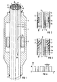
- a gamma thermometer is understood here as follows, as it is e.g. is described in EP-A1-0 243 579.
- thermocouple This consists of a rod surrounded by a cladding tube. At least one thermocouple is arranged in the rod in at least one cavity. In the area of the thermocouple, a rod part is arranged as a gamma absorber and as a thermal bridge.
- thermometers for the purpose of calibrating gamma thermometers, only the heating element method is used, namely outside and inside the reactor core.
- an artificial heating current noise is generated, so that shortened time constants can be obtained due to a special transformation process and so the relevant measured values (reactor flow) can be obtained much faster during the reactor operation using a "speed-up process". So here the heating current noise is used to determine time constants, whereas the noise of reactivity, coolant temperature, an analog / digital converter and an amplifier are only considered as disturbance variables and are not exploited will.
- thermal and nuclear transfer factors K i and K 2 of a gamma thermometer are determined using the heating current method in order to be able to make statements about its thermal and nuclear sensitivity. For this purpose, calibrations are carried out outside and inside the reactor core.
- the object of the invention is to provide a method for calibrating gamma thermometers with which the difficulties described can be avoided and with which the calibration of one or more gamma thermometers can also be carried out while a nuclear reactor, in particular a light water nuclear reactor, is in operation can be carried out in a precise manner - even without the use of electrical heating by means of a heating element, so that the values of the gamma flow or the proportional measured values measured with the gamma thermometer are a reliable image of the real conditions in the core.
- the claims 2 to 5 relate to the basic process feature and its configurations that fluctuations in the process variables 'reactivity' are recorded.
- the fluctuations of the thermohydraulic process variables, in particular the process variables 'coolant temperature', and the fluctuations due to vapor bubble formation in the primary coolant are closely linked to these fluctuations.
- Claims 6 and 7 relate to a calibration method which can be used both outside the operation of a nuclear reactor and during the operation of a nuclear reactor and which consists in that the time constant T * is approximately determined on the basis of artificially generated temperature fluctuations in the gamma thermometer by applying a fluctuating heating current to a heating element located on or in the heating element.
- the heating current is preferably subjected to random fluctuations.
- Such a fluctuation is also known under the term stochastic fluctuation or "pseudo random”. This heating current fluctuation method is only used for rough control or verification of the K * and T * values determined on the basis of the noise analysis of fluctuating process variables.
- the constancy of the calibration or the calibration factor K * can advantageously also be monitored.
- the Fourier analysis is generally suitable as a noise analysis.
- the method is preferred the autoregressive (AR) signal analysis applied, the configurations of which are described in claims 9 to 12.
- the cable bundle 1 consists of six Ni-Cr-Ni thermocouples 2 in the form of two-wire thermoelectric cables, each with the two signal lines 2.1 and 2.2 insulated from one another and to the outside, and a central heating cable 3 with a heating conductor 3.1.
- the cables 2, 3 are gas and watertight in a cladding tube 4 made of corrosion-resistant steel.
- the cable insulation KI envelops the conductors 2.1, 2.2 and 3.1 and consists, for example, of Al 2 O 3 .
- One of the thermocouples 2 is shown schematically with its "hot" solder joint 2a and with its "cold” solder joint 2b; the axes of the other thermocouples 4 are indicated by dash-dotted lines.
- a hollow cylindrical platinum body 5 is soldered or welded to the outer circumference of the cladding tube 4 above the hot soldering point 2a of the respective thermocouple 2.
- An outer envelope 6 encloses a gas space 7 filled with, for example, 1 bar argon.
- a part of this enveloping body 6 is also soldered or welded to the outer circumference of the enveloping tube 4 or the cable bundle 1 over the cold solder joint 2b.
- the connection points of the enveloping body 6 and the enveloping tube 1, which come into contact with the reactor water, are welded, as shown at points 8 and 9.
- the gamma radiation When operating in the reactor core, the gamma radiation is absorbed in the platinum body 5 (the illustration is not to scale, but only in principle) and heats it up.
- the heat flows mainly in the axial direction via the cable bundle 1 and then radially via the cladding tube 4 and the cladding body 6 to the cooling medium. Due to the axially asymmetrical structure of the gamma thermometer, the heat essentially only flows in the direction of the cold solder joint 2b. It is thereby achieved that the influence of the heat transfer from the detector surface into the cooling medium on the temperature at both solder joints is the same or that this heat transfer has no influence on the differential temperature between (2a) and (2b).
- the signal of the gamma thermometer (detector) is therefore independent of cooling conditions as well as heat and temperature gradients.
- the two solder joints 2a, 2b can be constructed as differential thermocouples in one cable, as shown, or as two absolute thermocouples in two cables.
- the absolute thermocouples in addition to the differential temperatures, the absolute temperatures can also be determined (as a level measurement in the event of loss of coolant).
- the gamma thermometer according to FIG. 2 essentially consists of a rod 10, which is surrounded by a cladding tube 4.
- a differential thermocouple 2 with hot and cold soldering points 2a, 2b is arranged in a channel 11 inside the gamma thermometer in addition to a heating cable 3, which is used for calibration with heating current.
- the rod 10 consists of platinum in the region of the thermocouple 2 and steel for the rest.
- the platinum rod part is surrounded as a platinum gamma absorber thermal bridge 12 within the cladding tube 4 by a tubular heat-insulating chamber 7 '. Both measuring points 2a, 2b of the differential thermocouple 2 can be located in the inner region of the chamber 7 '.
- External gamma radiation mainly causes part 12 to heat up through interactions. Since the atomic number and the density of platinum are significantly greater than the values of iron, the amount of heat introduced into platinum is also very large compared to the amount of heat introduced into iron or steel greater.
- platinum at least in the area of the differential thermocouple 2 the sensitivity of the gamma thermometer is greatly increased. The high sensitivity due to the choice of material makes it possible to change the design of the gamma thermometer or to reduce the longitudinal expansion in order to reduce the effects of power and temperature gradients in the reactor core, without reducing the sensitivity to known gamma thermometers. A heat flow to the surface forms in the heated part 12.
- the heat-insulating chamber 7 ' allows an axial flow to arise in part 12, which only bends outside the chamber 7' towards the cladding tube 4. From the temperature difference between the measuring point 2a and the comparative measuring point 2b of the differential thermocouple 2, the heat flow in the gamma-absorber thermal bridge 12 and from it the radiated gamma intensity with a small error range can be determined.
- the heat-insulating material in the chamber 7 ' is either, as explained in FIG. 1, argon or a solid material with low thermal conductivity.
- a platinum-gamma absorber thermal bridge 13 and a heat-insulating chamber 7 ′′ are arranged axially one behind the other, partially overlapping.
- the platinum-gamma absorber thermal bridge 13 touches the cladding tube 4 and thus the tube only at one point Outer skin of the gamma thermometer.
- the chamber 7 "can, like the chamber 7 'according to FIG. 2, contain argon or a solid material with low thermal conductivity.
- thermocouples hot and cold measuring point
- the thermocouples measure temperatures that correspond to the "flowing amounts of heat", which are the sum of all amounts of heat and corresponding to the paths.
- the heating current is selected as a pseudo-random telegraph signal.
- the temperature of the filament then also has a pseudo-random course - neglecting the time constant of the filament, see FIG. 4.
- the dimension of x is 1 / sec.
- the always existing excitation by fluctuations in the coolant temperature can also be used. If the coolant temperature fluctuations are almost uncorrelated in time compared to the sensor bandwidth, the requirement for a white excitation is met sufficiently well. What has been said above applies to the selection of the sampling time and the recording duration.
- the fluctuations in the sensor output signal can then also be analyzed again with AR analysis and the sensor time constant can be estimated.
- the prerequisite for an approximate white excitation due to coolant temperature fluctuations in one of the gamma thermometers is fulfilled.
- the excitation of the gamma thermometer by fluctuation of the gamma flow can also be evaluated for the AR analysis.
- This excitation must meet the requirement of a power density spectrum that is approximately white within the sensor bandwidth, and its power (amplitude) must be sufficient to lead to evaluable fluctuations in the sensor output signal. If the hot measuring point provides sufficient evidence of gamma flow fluctuations - possibly during part-load operation - a good direct calibration results from the determination of the associated time constant.
- the small amplitude of the fluctuations can be compensated for by measuring for a very long time. This is easier possible with the method proposed here because the function of the sensors is not impaired at all by the calibration measurement (without heating current).
- the performance and its influence on the calibration method can be increased by producing measuring elements and parts of the thermal bridge from platinum, because this increases the interactions with the gamma radiation.
- influences of the vapor bubble content can also have an effect on the cooling, in particular on the cold measuring point, and can therefore be measured by an analysis of the time constants.
- thermocouples with corresponding fluctuation analyzes
- the effects can also be separated and can thus be taken into account more easily in the end.
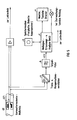
- a gamma thermometer as was explained with reference to FIGS. 1 to 3, or another suitable gamma thermometer is used and generally designated GT.
- the associated gamma thermometer measuring point which is important in the present case, is designated GT1.
- the voltage signal of the gamma thermometer measuring point GT1 is faded out of the signal path relevant for the control system via the isolation and compensation amplifier (a).
- (a) has three functions: galvanic isolation of the control technology (possibly safety-relevant) from the calibration device, compensation of the DC component of the measurement signal by adding a constant, adjustable compensation voltage and amplification of the remaining AC component for optimal control of the subsequent devices.
- the remaining alternating component is due to gamma flow and / or coolant fluctuations.
- the low-pass filter (b) serves to limit the band of the signal in order to avoid errors due to convolutions in the frequency domain during the subsequent digitization.
- the cut-off frequency of the low-pass filter should be selected to be less than half the sampling frequency.
- the measurement signal acquisition and analysis device (c) first digitizes the analog signal u (t) over a certain period of time and stores the data in a storage medium, e.g. Main computer memory, hard disk or diskette d. The data can then be analyzed and the calibration factor determined for the measuring point. Keyboard, monitor and printer e are provided for display and operation. If the calibration is to be monitored, a message is issued when the calibration factor changes, e.g. via a lamp f in the control room, or by hiding the measurement signal from the reactor monitoring system or by automatically adapting the gain factor of the gamma thermometer useful signal in accordance with the new calibration factor.
- a storage medium e.g. Main computer memory, hard disk or diskette d.
- Keyboard, monitor and printer e are provided for display and operation. If the calibration is to be monitored, a message is issued when the calibration factor changes, e.g. via a lamp f in the control room, or by hiding the measurement signal from the reactor monitoring system or by automatically adapting the gain
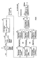
- the signal processing in the measurement signal detection and analysis device c takes place according to the diagram according to FIG. 6 in the following steps:
- the analog signal u (t) is first digitized by an analog-digital converter cl at cyclic time intervals of T A.
- the sampling time T A is about 1/40 to 1/10 of the smallest time constant of the measuring point.
- the data are read from the memory and an AR analysis is carried out (c3).
- the data x (k) are modeled by an auto-regressive model of order N:
- the time constants can be determined from the frequency response.
- the magnitude-frequency response of the measuring point - apart from a multiplicative constant - is determined from the AR parameters (c6):
- the kinks and thus the time constants can then be determined from the absolute frequency response in (c7).
- the calibration factor of the gamma thermometer or the measuring channel is then determined in (c10) using the relationship already given above.
- This calibration factor can now be used for a corresponding setting of the measuring amplifier for the measuring channel under consideration be det. If the calibration device is to monitor the constancy of the calibration factor, a comparison of the currently determined calibration factor with one or more previously determined calibration factors is carried out in (c11). If there is an impermissibly large difference between these values, a message is generated which is displayed at a suitable point, for example in the control room.
Landscapes
- Physics & Mathematics (AREA)
- Engineering & Computer Science (AREA)
- Plasma & Fusion (AREA)
- General Engineering & Computer Science (AREA)
- High Energy & Nuclear Physics (AREA)
- General Physics & Mathematics (AREA)
- Spectroscopy & Molecular Physics (AREA)
- Monitoring And Testing Of Nuclear Reactors (AREA)
Applications Claiming Priority (2)
| Application Number | Priority Date | Filing Date | Title |
|---|---|---|---|
| DE4003997 | 1990-02-09 | ||
| DE4003997 | 1990-02-09 |
Publications (1)
| Publication Number | Publication Date |
|---|---|
| EP0441215A1 true EP0441215A1 (fr) | 1991-08-14 |
Family
ID=6399810
Family Applications (1)
| Application Number | Title | Priority Date | Filing Date |
|---|---|---|---|
| EP91101067A Ceased EP0441215A1 (fr) | 1990-02-09 | 1991-01-28 | Méthode pour la détermination des facteurs de calibration d'un thermométre gamma, et application de la méthode |
Country Status (1)
| Country | Link |
|---|---|
| EP (1) | EP0441215A1 (fr) |
Cited By (4)
| Publication number | Priority date | Publication date | Assignee | Title |
|---|---|---|---|---|
| RU2198437C2 (ru) * | 2001-04-02 | 2003-02-10 | Открытое акционерное общество "Ракетно-космическая корпорация "Энергия" им. С.П. Королева" | Способ определения температуры оболочки твэла при экспериментальной отработке в ядерном реакторе и устройство для его реализации |
| CN115077744A (zh) * | 2022-06-10 | 2022-09-20 | 云南北方光电仪器有限公司 | 一种基于水浴法的热电偶时间常数测量装置及测量方法 |
| CN116625551A (zh) * | 2023-05-25 | 2023-08-22 | 辽宁省计量科学研究院 | 一种核电疲劳监测系统中温度传感器响应时间校准方法 |
| CN119294296A (zh) * | 2024-10-10 | 2025-01-10 | 中国原子能科学研究院 | 确定池式钠冷快堆的堆芯流量的方法 |
Citations (5)
| Publication number | Priority date | Publication date | Assignee | Title |
|---|---|---|---|---|
| GB2092300A (en) * | 1981-01-30 | 1982-08-11 | Electricite De France | In-situ calibration of local power measuring devices for nuclear reactors |
| US4393025A (en) * | 1978-06-07 | 1983-07-12 | Leyse Robert H | Method of and apparatus for measuring the power distribution in nuclear reactor cores |
| US4634570A (en) * | 1983-07-05 | 1987-01-06 | Scandpower, Inc. | Process and device for measuring the local thermal power in a nuclear reactor |
| EP0243579A1 (fr) * | 1986-02-03 | 1987-11-04 | Siemens Aktiengesellschaft | Thermomètre gamma |
| EP0322541A2 (fr) * | 1987-12-25 | 1989-07-05 | Mitsubishi Denki Kabushiki Kaisha | Appareil pour mesurer la distribution de la puissance d'un réacteur nucléaire |
-
1991
- 1991-01-28 EP EP91101067A patent/EP0441215A1/fr not_active Ceased
Patent Citations (5)
| Publication number | Priority date | Publication date | Assignee | Title |
|---|---|---|---|---|
| US4393025A (en) * | 1978-06-07 | 1983-07-12 | Leyse Robert H | Method of and apparatus for measuring the power distribution in nuclear reactor cores |
| GB2092300A (en) * | 1981-01-30 | 1982-08-11 | Electricite De France | In-situ calibration of local power measuring devices for nuclear reactors |
| US4634570A (en) * | 1983-07-05 | 1987-01-06 | Scandpower, Inc. | Process and device for measuring the local thermal power in a nuclear reactor |
| EP0243579A1 (fr) * | 1986-02-03 | 1987-11-04 | Siemens Aktiengesellschaft | Thermomètre gamma |
| EP0322541A2 (fr) * | 1987-12-25 | 1989-07-05 | Mitsubishi Denki Kabushiki Kaisha | Appareil pour mesurer la distribution de la puissance d'un réacteur nucléaire |
Cited By (4)
| Publication number | Priority date | Publication date | Assignee | Title |
|---|---|---|---|---|
| RU2198437C2 (ru) * | 2001-04-02 | 2003-02-10 | Открытое акционерное общество "Ракетно-космическая корпорация "Энергия" им. С.П. Королева" | Способ определения температуры оболочки твэла при экспериментальной отработке в ядерном реакторе и устройство для его реализации |
| CN115077744A (zh) * | 2022-06-10 | 2022-09-20 | 云南北方光电仪器有限公司 | 一种基于水浴法的热电偶时间常数测量装置及测量方法 |
| CN116625551A (zh) * | 2023-05-25 | 2023-08-22 | 辽宁省计量科学研究院 | 一种核电疲劳监测系统中温度传感器响应时间校准方法 |
| CN119294296A (zh) * | 2024-10-10 | 2025-01-10 | 中国原子能科学研究院 | 确定池式钠冷快堆的堆芯流量的方法 |
Similar Documents
| Publication | Publication Date | Title |
|---|---|---|
| DE69019642T2 (de) | Einrichtung und Elektrode zur lokalen Ueberwachung der Qualität des Hochtemperaturwassers für Kraftwerke. | |
| DE69424489T2 (de) | Vorrichtung für thermische Analyse | |
| EP2027441B1 (fr) | Dispositif de mesure de niveau | |
| EP3551981B1 (fr) | Procédé d'étalonnage in situ d'un thermomètre | |
| DE3605501C2 (fr) | ||
| DE3104177A1 (de) | Korrosionsmessung mit sekundaerer temperaturkompensation | |
| EP3234515B1 (fr) | Appareil de mesure de débit thermique avec fonction de diagnostic | |
| DE2515281A1 (de) | Einrichtung zum messen der verschmutzung von metalloberflaechen | |
| DE3202560C2 (de) | Verfahren zur in situ erfolgenden Eichung eines Gerätes zur örtlichen Leistungskontrolle in einem Kernreaktor | |
| DE69504734T2 (de) | Verfahren zur Charakterisierung einer Gasmischung durch katalytische Oxidation | |
| DE102013108819A1 (de) | Strahlungsanalysator und Verfahren zur Strahlungsanalyse | |
| DE2758994A1 (de) | Messfuehler zum bestimmen von waermestroemen durch ein festes medium | |
| DE2910927A1 (de) | Vorrichtung zur messung der oertlichen leistung in einer brennstoffanordnung eines kernreaktors | |
| DE102007023824A1 (de) | Thermischer Massendurchflussmesser | |
| DE69837314T2 (de) | Schnelle thermische Analysevorrichtung | |
| EP0441215A1 (fr) | Méthode pour la détermination des facteurs de calibration d'un thermométre gamma, et application de la méthode | |
| DE69009412T2 (de) | Einrichtung zur Temperaturregelung. | |
| DE3132057A1 (de) | Roentgengenerator mit selbsttaetiger korrektur eines die dosis bestimmenden aufnahmeparameters | |
| DE2731381A1 (de) | Messwertwandler | |
| DE3143330A1 (de) | Selbst strom liefernder neutronendetektor | |
| DE10003676B4 (de) | Verfahren und Vorrichtung zur Bestimmung der Konzentrationen eines H2/He-Gasgemisches | |
| DE10253905A1 (de) | Instrument zum Messen der von einer Quelle kohärenter oder inkohärenter Strahlung, insbesondere von einer Laser-Strahlungsquelle abgegebenen Leistung und damit verbundenes Verfahren | |
| DE3301627C2 (fr) | ||
| EP3789743B1 (fr) | Système et procédé de génération d'un signal de prédiction ainsi que caméra thermique | |
| DE69106608T2 (de) | Verfahren zur Bewertung und Eichung der von einem Röntgenfilm aufgenommenen Belichtung. |
Legal Events
| Date | Code | Title | Description |
|---|---|---|---|
| PUAI | Public reference made under article 153(3) epc to a published international application that has entered the european phase |
Free format text: ORIGINAL CODE: 0009012 |
|
| 17P | Request for examination filed |
Effective date: 19910610 |
|
| AK | Designated contracting states |
Kind code of ref document: A1 Designated state(s): DE ES FR SE |
|
| 17Q | First examination report despatched |
Effective date: 19940603 |
|
| STAA | Information on the status of an ep patent application or granted ep patent |
Free format text: STATUS: THE APPLICATION HAS BEEN REFUSED |
|
| 18R | Application refused |
Effective date: 19950807 |
|
| K1C1 | Correction of patent application (title page) published |
Effective date: 19910814 |