EP0441223A2 - Hydraulically or hand operated riveting tool - Google Patents
Hydraulically or hand operated riveting tool Download PDFInfo
- Publication number
- EP0441223A2 EP0441223A2 EP91101115A EP91101115A EP0441223A2 EP 0441223 A2 EP0441223 A2 EP 0441223A2 EP 91101115 A EP91101115 A EP 91101115A EP 91101115 A EP91101115 A EP 91101115A EP 0441223 A2 EP0441223 A2 EP 0441223A2
- Authority
- EP
- European Patent Office
- Prior art keywords
- device housing
- rotary head
- sleeve
- rear end
- spindle
- Prior art date
- Legal status (The legal status is an assumption and is not a legal conclusion. Google has not performed a legal analysis and makes no representation as to the accuracy of the status listed.)
- Withdrawn
Links
Images


Classifications
-
- B—PERFORMING OPERATIONS; TRANSPORTING
- B21—MECHANICAL METAL-WORKING WITHOUT ESSENTIALLY REMOVING MATERIAL; PUNCHING METAL
- B21J—FORGING; HAMMERING; PRESSING METAL; RIVETING; FORGE FURNACES
- B21J15/00—Riveting
- B21J15/38—Accessories for use in connection with riveting, e.g. pliers for upsetting; Hand tools for riveting
- B21J15/386—Pliers for riveting
-
- B—PERFORMING OPERATIONS; TRANSPORTING
- B21—MECHANICAL METAL-WORKING WITHOUT ESSENTIALLY REMOVING MATERIAL; PUNCHING METAL
- B21J—FORGING; HAMMERING; PRESSING METAL; RIVETING; FORGE FURNACES
- B21J15/00—Riveting
- B21J15/02—Riveting procedures
- B21J15/04—Riveting hollow rivets mechanically
- B21J15/043—Riveting hollow rivets mechanically by pulling a mandrel
-
- B—PERFORMING OPERATIONS; TRANSPORTING
- B25—HAND TOOLS; PORTABLE POWER-DRIVEN TOOLS; MANIPULATORS
- B25B—TOOLS OR BENCH DEVICES NOT OTHERWISE PROVIDED FOR, FOR FASTENING, CONNECTING, DISENGAGING, OR HOLDING
- B25B27/00—Hand tools, specially adapted for fitting together or separating parts or objects whether or not involving some deformation, not otherwise provided for
- B25B27/0007—Tools for fixing internally screw-threaded tubular fasteners
-
- B—PERFORMING OPERATIONS; TRANSPORTING
- B25—HAND TOOLS; PORTABLE POWER-DRIVEN TOOLS; MANIPULATORS
- B25B—TOOLS OR BENCH DEVICES NOT OTHERWISE PROVIDED FOR, FOR FASTENING, CONNECTING, DISENGAGING, OR HOLDING
- B25B27/00—Hand tools, specially adapted for fitting together or separating parts or objects whether or not involving some deformation, not otherwise provided for
- B25B27/0007—Tools for fixing internally screw-threaded tubular fasteners
- B25B27/0014—Tools for fixing internally screw-threaded tubular fasteners motor-driven
-
- Y—GENERAL TAGGING OF NEW TECHNOLOGICAL DEVELOPMENTS; GENERAL TAGGING OF CROSS-SECTIONAL TECHNOLOGIES SPANNING OVER SEVERAL SECTIONS OF THE IPC; TECHNICAL SUBJECTS COVERED BY FORMER USPC CROSS-REFERENCE ART COLLECTIONS [XRACs] AND DIGESTS
- Y10—TECHNICAL SUBJECTS COVERED BY FORMER USPC
- Y10T—TECHNICAL SUBJECTS COVERED BY FORMER US CLASSIFICATION
- Y10T29/00—Metal working
- Y10T29/53—Means to assemble or disassemble
- Y10T29/53709—Overedge assembling means
- Y10T29/53717—Annular work
- Y10T29/53726—Annular work with second workpiece inside annular work one workpiece moved to shape the other
- Y10T29/5373—Annular work with second workpiece inside annular work one workpiece moved to shape the other comprising driver for snap-off-mandrel fastener; e.g., Pop [TM] riveter
- Y10T29/53752—Annular work with second workpiece inside annular work one workpiece moved to shape the other comprising driver for snap-off-mandrel fastener; e.g., Pop [TM] riveter having rotary drive mechanism
-
- Y—GENERAL TAGGING OF NEW TECHNOLOGICAL DEVELOPMENTS; GENERAL TAGGING OF CROSS-SECTIONAL TECHNOLOGIES SPANNING OVER SEVERAL SECTIONS OF THE IPC; TECHNICAL SUBJECTS COVERED BY FORMER USPC CROSS-REFERENCE ART COLLECTIONS [XRACs] AND DIGESTS
- Y10—TECHNICAL SUBJECTS COVERED BY FORMER USPC
- Y10T—TECHNICAL SUBJECTS COVERED BY FORMER US CLASSIFICATION
- Y10T29/00—Metal working
- Y10T29/53—Means to assemble or disassemble
- Y10T29/53709—Overedge assembling means
- Y10T29/53717—Annular work
- Y10T29/53726—Annular work with second workpiece inside annular work one workpiece moved to shape the other
- Y10T29/5373—Annular work with second workpiece inside annular work one workpiece moved to shape the other comprising driver for snap-off-mandrel fastener; e.g., Pop [TM] riveter
- Y10T29/53757—Annular work with second workpiece inside annular work one workpiece moved to shape the other comprising driver for snap-off-mandrel fastener; e.g., Pop [TM] riveter having allochiral actuating handles
Definitions
- the invention relates to a riveting device, operated hydraulically or as a hand riveting device with two articulated levers for carrying out the actual riveting process and a rotating mandrel for screwing on the rivet nut and for unscrewing after the riveting process.
- a riveting process can be carried out without difficulty; however, a large number of handles are required, which represent a burden on the operator, which leads to fatigue during longer working hours, and in addition, the execution of the individual handles requires a greater expenditure of time.
- First the lever arms have to be opened completely and the mandrel has to be set in rotation.
- a hand knob of a pull tube attached to the threaded mandrel is pushed back while the rivet nut is screwed onto the threaded mandrel between the thumb and index finger on the device housing.
- the actual riveting process is carried out by pressing the two lever arms inwards.
- the threaded mandrel is then unscrewed from the rivet nut by actuating the pull tube.
- the invention is therefore based on the object of making available a riveting device which enables inexpensive operation for carrying out the riveting process and in which the operator's signs of fatigue and the processing time are reduced.
- the invention consists in that a rotating device in the form of a rotary head is provided at the rear end of the device housing opposite the threaded mandrel, which is connected in a rotationally fixed manner to a pulling spindle connected to the threaded mandrel projecting at the front end of the device housing.
- the invention further proposes that the rotary head surrounds the rear end of the device housing in a cylinder-like manner and is connected to a driver which drives a transmission which is arranged at the rear end of the tension spindle.
- Rotational markings are expediently attached to the device housing.
- the rotary head is arranged on the side of the device housing outside the plane of the handle tubes and is connected to the traction spindle via a gear mechanism. It is expediently provided that the rotary shaft of the rotary head runs in a plane perpendicular to the tension spindle and that the rotary shaft carries a bevel gear which meshes with a bevel gear seated on the tension spindle.
- the rotary head is mounted on a sleeve rotatably seated on the rear end of the device housing, the sleeve can be set in different positions according to the type of operation of the device.
- the sleeve advantageously carries a fixing bolt which engages in recesses which are made on the device housing. It can also be expediently provided that the sleeve is infinitely adjustable in its rotational position by a friction fit on the device housing.
- This device can be adapted to the working method by the operator, is relatively light and enables easier operation.
- the device has a relatively low weight, is shorter than known devices, therefore easier to handle and is characterized by a compact design. It requires relatively little effort.
- the threaded mandrel 1 protrudes from the mouthpiece 2, which is fastened with the aid of a lock nut 3.
- the mandrel holder 4 is located in the front sleeve 5, in which the mouthpiece 2 is also fixed. It is fastened with a rear lock nut 6.
- the handle tubes 8 of the levers are fastened by bolts 9 to the front device housing 7.
- the front end of the pliers legs 14 is articulated, the rear end of which is fastened to the device with bolts 9.
- On the front housing 7 is a lifting screw 13 with an O-ring 12 attached.
- the traction spindle 16 runs through the rear housing 15.
- a guide sleeve 18 is attached to the rear housing 15 with the aid of setscrews 17, in which a planetary gear 19 sits and is fixed by the setscrews 20.
- a driver 21 extends from the planetary gear 19, to which a rotary head 22 is fastened by means of threaded pins 23.
- the planetary gear 19 is actuated via the driver 21, which in turn sets the spindle 16 in rotation. In this way, it is possible to screw the mandrel onto the blind rivet nut by rotating the rotary head 22 and to unscrew it again after the rivet setting process.
- a sleeve 41 is seated on the device housing 14 and is designed to be rotatable with respect to the device housing.
- a bore 42 is provided in the sleeve 41, through which a fixing bolt (not shown) engages in a recess 43 which is provided in the device housing 40.
- the sleeve 41 can thus be fixed in various positions with respect to the device housing 40 by a plurality of recesses 43 distributed over the circumference. But it is also possible to provide a friction fit, so that the sleeve 41 is infinitely adjustable with respect to the device housing 40.
- a rotary head attached laterally on this can also be brought into a position relative to the device housing 40, as may be required during assembly or as is most convenient for the operator.
- a bevel gear 45 is connected to the rotary head 44, the shaft 46 of which runs perpendicular to the feed spindle 16.
- the traction spindle 16 is connected to an extension spindle 47 which carries a bevel gear 48 which meshes with the bevel gear 45 of the shaft 46 to which the rotary head 44 is connected.
- a bolt not shown, which sits in a bore 49 in the rotary head, this is with the Shaft 46 non-rotatably connected.
- the mandrel 1 can be rotated via the pulling spindle 16 in order to thread the threaded rivet nut and to unscrew the threaded mandrel 1 after the riveting process.
- the invention thus makes available a device for setting threaded rivet nuts in which the rotation of the threaded mandrel takes place in a simple manner with the aid of the threaded head 22, 44 and the threaded head 44 can be brought into an optimal position.
Landscapes
- Engineering & Computer Science (AREA)
- Mechanical Engineering (AREA)
- Press Drives And Press Lines (AREA)
- Insertion Pins And Rivets (AREA)
- Automatic Tool Replacement In Machine Tools (AREA)
Abstract
Bei einem Nietgerät mit zwei Gelenkhebeln zum Ausführen des eigentlichen Nietvorganges und eines in Drehung versetzbaren Gewindedorns zum Aufschrauben der Nietmutter und zum Herausschrauben nach dem Nietsetzvorgang ist dem Gewindedorn (1) gegenüberliegenden, hinteren Ende des Gerätegehäuses (15, 18) eine Dreheinrichtung in Form eines Drehkopfes (22) vorgesehen, der mit einer mit dem am vorderen Ende des Gerätes vorstehenden Gewindedorn (1) verbundenen Zugspindel (16) drehfest verbunden ist.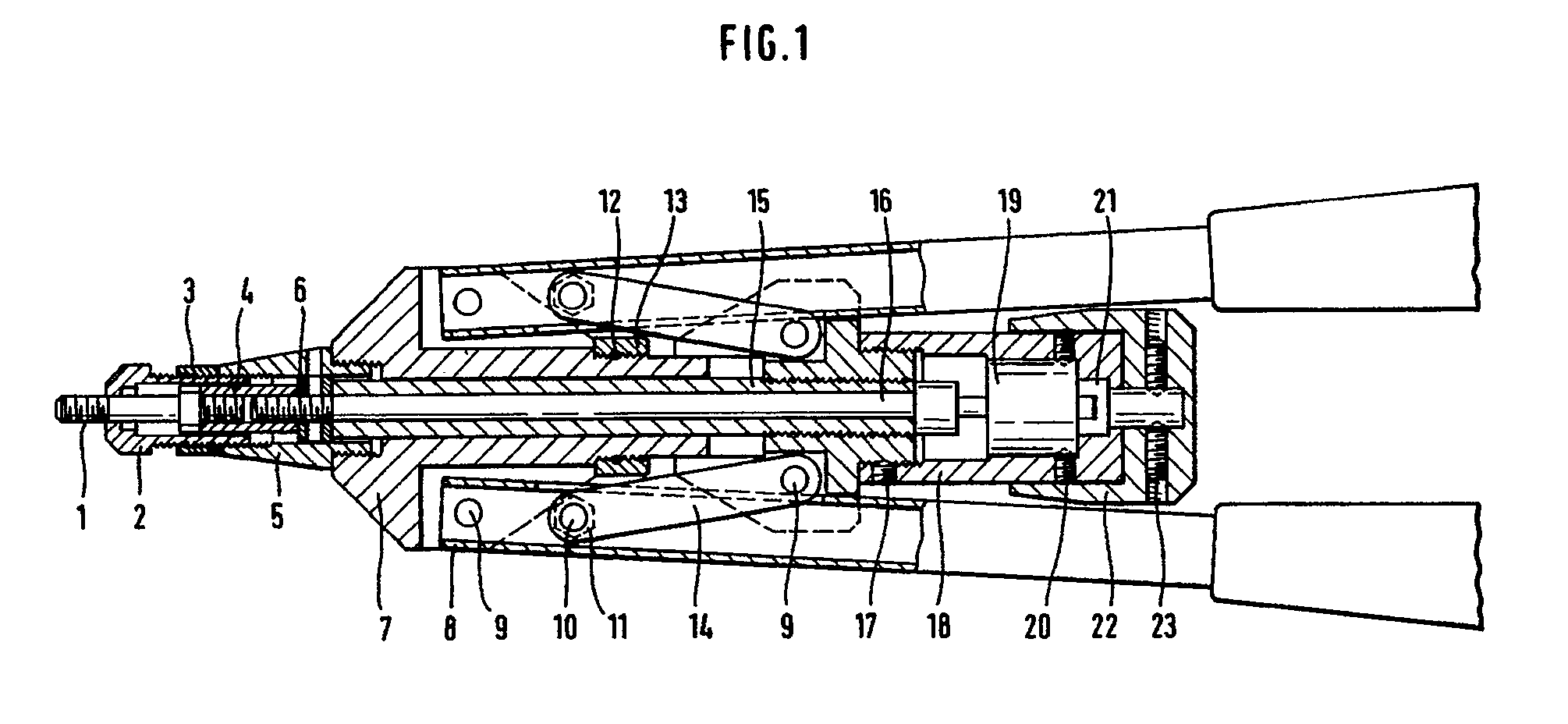
Description
Die Erfindung betrifft ein Nietgerät, hydraulisch betätigt oder als Handnietgerät mit zwei Gelenkhebeln zum Ausführen des eigentlichen Nietvorganges und eines in Drehung versetzbaren Gewindedorns zum Aufschrauben der Nietmutter und zum Herausschrauben nach dem Nietsetzvorgang.The invention relates to a riveting device, operated hydraulically or as a hand riveting device with two articulated levers for carrying out the actual riveting process and a rotating mandrel for screwing on the rivet nut and for unscrewing after the riveting process.
Mit derartigen Geräten läßt sich zwar ohne Schwierigkeiten ein Nietvorgang durchführen; es ist jedoch eine Vielzahl von Handgriffen erforderlich, die eine Belastung der Bedienungsperson darstellen, was bei längeren Arbeitszeiten zu Ermüdungserscheinungen führt, und außerdem erfordert die Durchführung der einzelnen Handgriffe einen großeren Zeitaufwand. So müssen zunächst die Hebelarme vollständig geöffnet werden, und der Gewindedorn ist in Drehung zu versetzen. Zu diesem Zweck ist es bekannt, daß ein Handknauf eines am Gewindedorn angebrachten Zugrohres zurückgeschoben wird, während die Einnietmutter zwischen Daumen und Zeigefinger am Gerätegehäuse auf den Gewindedorn aufgeschraubt wird. Der eigentliche Nietvorgang wird durchgeführt, indem die zwei Hebelarme nach innen zusammengedrückt werden. Danach erfolgt durch Betätigung des Zugrohres das Ausschrauben des Gewindedorns aus der Nietmutter. Um die Bedienung des Nietvorganges zu vereinfachen, ist es bereits bekannt, am Ende des Gewindedorns einen Elektromotor vorzusehen, der den Gewindedorn in Drehung versetzen kann. Der Elektromotor mit dem dazu erforderlichen Akku führt jedoch dazu, daß das Gerät ein verhältnismäßig großes Gewicht bekommt, so daß der Umgang mit dem Gerät dadurch erschwert wird und die Bedienungsperson verhältnismäßig viel Kraft aufzuwenden hat.With such devices, a riveting process can be carried out without difficulty; however, a large number of handles are required, which represent a burden on the operator, which leads to fatigue during longer working hours, and in addition, the execution of the individual handles requires a greater expenditure of time. First the lever arms have to be opened completely and the mandrel has to be set in rotation. For this purpose it is known that a hand knob of a pull tube attached to the threaded mandrel is pushed back while the rivet nut is screwed onto the threaded mandrel between the thumb and index finger on the device housing. The actual riveting process is carried out by pressing the two lever arms inwards. The threaded mandrel is then unscrewed from the rivet nut by actuating the pull tube. In order to simplify the operation of the riveting process, it is already known to provide an electric motor at the end of the threaded mandrel, which rotates the threaded mandrel can move. However, the electric motor with the required battery leads to the device being given a relatively large weight, so that handling of the device is thereby made more difficult and the operator has to use a relatively large amount of force.
Der Erfindung liegt daher die Aufgabe zugrunde, ein Nietgerät verfügbar zu machen, das eine günstige Bedienung zur Durchführung des Nietvorgangs ermöglicht, bei der Ermüdungserscheinungen der Bedienungsperson sowie die Verarbeitungszeit herabgesetzt sind.The invention is therefore based on the object of making available a riveting device which enables inexpensive operation for carrying out the riveting process and in which the operator's signs of fatigue and the processing time are reduced.
Die Erfindung besteht darin, daß an dem dem Gewindedorn gegenüberliegenden, hinteren Ende des Gerätegehäuses eine Dreheinrichtung in Form eines Drehkopfes vorgesehen ist, der mit einer mit dem am vorderen Ende des Gerätegehäusees vorstehenden Gewindedorn verbundenen Zugspindel drehfest verbunden ist.The invention consists in that a rotating device in the form of a rotary head is provided at the rear end of the device housing opposite the threaded mandrel, which is connected in a rotationally fixed manner to a pulling spindle connected to the threaded mandrel projecting at the front end of the device housing.
Um den Kraftaufwand zu verringern, schlägt die Erfindung weiter vor, daß der Drehkopf das hintere Ende des Gerätegehäusees zylinderartig umgibt und mit einem Mitnehmer verbunden ist, der ein Getriebe antreibt, das am hinteren Ende der Zugspindel angeordnet ist.In order to reduce the expenditure of force, the invention further proposes that the rotary head surrounds the rear end of the device housing in a cylinder-like manner and is connected to a driver which drives a transmission which is arranged at the rear end of the tension spindle.
Zweckmäßig sind am Gerätegehäuse Drehmarkierungen angebracht.Rotational markings are expediently attached to the device housing.
Zur verbesserten Bedienung kann vorgesehen sein, daß der Drehkopf seitlich am Gerätegehäuse außerhalb der Ebene der Griffrohre angeordnet und über ein Zahnradgetriebe mit der Zugspindel verbunden ist. Dabei ist zweckmäßig vorgesehen, daß die Drehwelle des Drehkopfes in einer Ebene senkrecht zur Zugspindel verläuft und daß die Drehwelle ein Kegelzahnrad trägt, das mit einem auf der Zugspindel sitzenden Kegelzahnrad kämmt.For improved operation, it can be provided that the rotary head is arranged on the side of the device housing outside the plane of the handle tubes and is connected to the traction spindle via a gear mechanism. It is expediently provided that the rotary shaft of the rotary head runs in a plane perpendicular to the tension spindle and that the rotary shaft carries a bevel gear which meshes with a bevel gear seated on the tension spindle.
Gemäß einer vorteilhaften Ausführungsform ist der Drehkopf auf einer drehbar auf dem hinteren Ende des Gerätegehäusees sitzenden Hülse montiert, wobei die Hülse entsprechend der Art der Bedienung des Gerätes in verschiedenen Stellungen festlegbar ist.According to an advantageous embodiment, the rotary head is mounted on a sleeve rotatably seated on the rear end of the device housing, the sleeve can be set in different positions according to the type of operation of the device.
Dazu trägt mit Vorteil die Hülse einen Festlegebolzen, der in Ausnehmungen eingreift, die auf dem Gerätegehäuse angebracht sind. Es kann auch zweckmäßig vorgesehen sein, daß die Hülse urch einen Reibesitz auf dem Gerätegehäuse stufenlos in ihrer Drehstellung einstellbar ist.For this purpose, the sleeve advantageously carries a fixing bolt which engages in recesses which are made on the device housing. It can also be expediently provided that the sleeve is infinitely adjustable in its rotational position by a friction fit on the device housing.
Dieses Gerät kann von der Bedienungsperson an die Arbeitsweise angepaßt werden, ist verhältnismäßig leicht und ermöglicht eine erleichterte Bedienung. Das Gerät besitzt ein verhältnismäßig geringes Gewicht, ist kürzer als bekannte Geräte, dadurch besser handhabbar und zeichnet sich durch eine kompakte Bauweise aus. Es erfordert einen verhältnismäßig geringen Kraftaufwand.This device can be adapted to the working method by the operator, is relatively light and enables easier operation. The device has a relatively low weight, is shorter than known devices, therefore easier to handle and is characterized by a compact design. It requires relatively little effort.
Die Erfindung soll nachstehend anhand eines Ausführungsbeispiels unter Bezugnahme auf die beigefügten Zeichnungen näher erläutert werden.The invention will be explained below using an exemplary embodiment with reference to the accompanying drawings.
In den Zeichnungen zeigen:
- Fig. 1
- ein Handnietgerät für Blindnietmuttern im Schnitt;
- Fig. 2
- eine abgewandelte Darstellung der Dreheinrichtung im Schnitt für ein Gerät nach Fig. 1.
- Fig. 1
- a hand riveter for blind rivet nuts in section;
- Fig. 2
- a modified representation of the rotating device in section for a device according to FIG. 1.
Bei dem in Fig. 1 dargestellten Handnietgerät für Blindnietmuttern steht der Gewindedorn 1 aus dem Mundstück 2 hervor, das mit Hilfe einer Kontermutter 3 befestigt ist. Die Gewindedornaufnahme 4 befindet sich in der vorderen Hülse 5, in der auch das Mundstück 2 festgelegt ist. Die Befestigung erfolgt mit einer hinteren Kontermutter 6. An dem vorderen Gerätegehäuse 7 sind die Griffrohre 8 der Hebel durch Bolzen 9 befestigt. Mit Hilfe eines Gewindebolzens 10 und einer Sicherungsmutter 11 ist das vordere Ende der Zangenschenkel 14 angelenkt, deren hinteres Ende mit Bolzen 9 am Gerät befestigt ist. Am vorderen Gehäuse 7 ist eine Hubstellschraube 13 mit O-Ring 12 angebracht. Durch das hintere Gehäuse 15 verläuft die Zugspindel 16. Am hinteren Gehäuse 15 ist mit Hilfe von Gewindestiften 17 eine Führungshülse 18 angebracht, in der ein Planetengetriebe 19 sitzt und durch die Gewindestifte 20 festgelegt ist. Von dem Planetengetriebe 19 erstreckt sich ein Mitnehmer 21, an dem ein Drehkopf 22 durch Gewindestifte 23 befestigt ist.In the hand riveter for blind rivet nuts shown in FIG. 1, the threaded mandrel 1 protrudes from the mouthpiece 2, which is fastened with the aid of a
Beim Drehen des Drehkopfes 22 wird über den Mitnehmer 21 das Planetengetriebe 19 betätigt, das wiederum die Spindel 16 in Drehung versetzt. Auf diese Weise ist es möglich, durch Drehung des Drehkopfes 22 den Gewindedorn auf die Blindnietmutter aufzuschrauben und nach dem Nietsetzvorgang wieder herauszuschrauben.When turning the
In Fig. 2 ist eine abgewandelte Ausführungsform dargestellt. Auf dem Gerätegehäuse 14 sitzt eine Hülse 41, die in Bezug auf das Gerätegehäuse drehbar gestaltet ist. In der Hülse 41 ist eine Bohrung 42 vorgesehen, durch die ein nicht dargestellter Festlegebolzen in eine Ausnehmung 43 eingreift, die im Gerätegehäuse 40 vorgesehen ist. Durch eine Vielzahl über den Umfang verteilter Ausnehmungen 43 kann so die Hülse 41 in verschiedenen Stellungen in Bezug auf das Gerätegehäuse 40 festgelegt werden. Es ist aber auch möglich, einen Reibesitz vorzusehen, so daß die Hülse 41 stufenlos in Bezug auf das Gerätegehäuse 40 einstellbar ist. Mit der Hülse 41 kann somit auch ein seitlich auf dieser angebrachter Drehkopf in eine Lage relativ zum Gerätegehäuse 40 gebracht werden, wie es Umstände bei der Montage erforderlich machen oder wie es der Bedienungsperson am angenehmsten ist. Mit dem Drehkopf 44 ist ein Kegelzahnrad 45 verbunden, dessen Welle 46 senkrecht zur Zugspindel 16 verläuft.2 shows a modified embodiment. A
Die Zugspindel 16 ist mit einer Verlängerungsspindel 47 verbunden, die ein Kegelzahnrad 48 trägt, das mit dem Kegelzahnrad 45 der Welle 46 kämmt, mit der der Drehkopf 44 verbunden ist. Mit Hilfe eines nicht dargestellten Bolzens, der in einer Bohrung 49 im Drehkopf sitzt, ist dieser mit der Welle 46 drehfest verbunden. Auf diese Art und Weise kann mit Hilfe des seitlich angeordneten Drehkopfes 44 über die Zugspindel 16 der Dorn 1 gedreht werden, um die Gewindenietmutter aufzufädeln und nach dem Nietvorgang den Gewindedorn 1 herauszudrehen. Die Erfindung macht somit ein Gerät zum Setzen von Gewindenietmuttern verfügbar, bei dem die Drehung des Gewindedorns mit Hilfe des Gewindekopfes 22, 44 in einfacher Weise erfolgt und der Gewindekopf 44 in eine optimale Stellung gebracht werden kann.The
Claims (9)
dadurch gekennzeichnet,
daß an dem dem Gewindedorn (1) gegenüberliegenden, hinteren Ende des Gerätegehäuses (15, 18) eine Dreheinrichtung in Form eines Drehkopfes (22) vorgesehen ist, der mit einer mit dem am vorderen Ende des Gerätes vorstehenden Gewindedorn (1) verbundenen Zugspindel (16) drehfest verbunden ist.Riveting device, hydraulically operated or as a hand riveting device with two articulated levers for carrying out the actual riveting process and a threaded mandrel that can be set in rotation for screwing on the rivet nut and for unscrewing after the riveting process,
characterized,
that at the rear end of the device housing (15, 18) opposite the threaded mandrel (1) there is provided a rotating device in the form of a rotary head (22) which is connected to a pull spindle (16) connected to the threaded mandrel (1) projecting from the front end of the device ) is non-rotatably connected.
dadurch gekennzeichnet, daß der Drehkopf (22) das hintere Ende des Gerätegehäuses (15, 18) zylinderartig umgibt und mit einem Mitnehmer (21) verbunden ist, der ein Getriebe (19) antreibt, das am hinteren Ende der Zugspindel (16) angeordnet ist.Device according to claim 1,
characterized in that the rotary head (22) surrounds the rear end of the device housing (15, 18) in a cylinder-like manner and is connected to a driver (21) which drives a gear (19) which is arranged at the rear end of the traction spindle (16) .
dadurch gekennzeichnet, daß am Gerätegehäuse (17, 18) Drehmarkierungen angebracht sind.Device according to claim 1 or 2,
characterized in that rotary markings are attached to the device housing (17, 18).
dadurch gekennzeichnet, daß der Drehkopf seitlich am Gerätegehäuse (17, 18) außerhalb der Ebene der Griffrohre (8) angeordnet und über ein Zahnradgetriebe (19) mit der Zugspindel (16) verbunden ist.Device according to claim 1,
characterized in that the rotary head is arranged on the side of the device housing (17, 18) outside the plane of the handle tubes (8) and is connected to the tension spindle (16) via a gear mechanism (19).
dadurch gekennzeichnet, daß die Drehwelle (46) des Drehkopfes (44) in einer Ebene senkrecht zur Zugspindel (16) verläuft und daß die Drehwelle (46) ein Kegelzahnrad (45) trägt, das mit einem auf der Zugspindel (16) sitzenden Kegelzahnrad (47) kämmt.Device according to claim 4,
characterized in that the rotary shaft (46) of the rotary head (44) extends in a plane perpendicular to the feed screw (16) and in that the rotary shaft (46) carries a bevel gear (45) which with combs a bevel gear (47) seated on the tension spindle (16).
dadurch gekennzeichnet, daß der Drehkopf (44) auf einer drehbar auf dem hinteren Ende des Gerätegehäusees sitzenden Hülse (41) montiert ist.Device according to one of claims 4 or 5,
characterized in that the rotary head (44) is mounted on a sleeve (41) rotatably seated on the rear end of the device housing.
dadurch gekennzeichnet, daß die Hülse (41) in verschiedenen Stellungen festlegbar ist.Device according to claim 6,
characterized in that the sleeve (41) can be fixed in different positions.
dadurch gekennzeichnet, daß die Hülse (41) einen Festlegebolzen trägt, der in Ausnehmungen (43) eingreift, die auf dem Gerätegehäuse (40) angebracht sind.Device according to claim 7,
characterized in that the sleeve (41) carries a locking bolt which engages in recesses (43) which are provided on the device housing (40).
dadurch gekennzeichnet, daß die Hülse (41) durch einen Reibesitz auf dem Gerätegehäuse (40) stufenlos in ihrer Drehstellung einstellbar ist.Device according to claim 7,
characterized in that the sleeve (41) is infinitely adjustable in its rotational position by a friction fit on the device housing (40).
Applications Claiming Priority (2)
| Application Number | Priority Date | Filing Date | Title |
|---|---|---|---|
| DE9001315U | 1990-02-06 | ||
| DE9001315U DE9001315U1 (en) | 1989-11-15 | 1990-02-06 | Hand riveter |
Publications (2)
| Publication Number | Publication Date |
|---|---|
| EP0441223A2 true EP0441223A2 (en) | 1991-08-14 |
| EP0441223A3 EP0441223A3 (en) | 1992-03-04 |
Family
ID=6850716
Family Applications (1)
| Application Number | Title | Priority Date | Filing Date |
|---|---|---|---|
| EP19910101115 Withdrawn EP0441223A3 (en) | 1990-02-06 | 1991-01-29 | Hydraulically or hand operated riveting tool |
Country Status (5)
| Country | Link |
|---|---|
| US (1) | US5079818A (en) |
| EP (1) | EP0441223A3 (en) |
| CA (1) | CA2035795C (en) |
| CS (1) | CS29891A2 (en) |
| RU (1) | RU1831408C (en) |
Cited By (1)
| Publication number | Priority date | Publication date | Assignee | Title |
|---|---|---|---|---|
| DE102017104824A1 (en) | 2017-03-08 | 2018-09-13 | Huarui Wen | Automatic retraction lever rivet nut pliers |
Families Citing this family (14)
| Publication number | Priority date | Publication date | Assignee | Title |
|---|---|---|---|---|
| DE9115444U1 (en) * | 1991-12-13 | 1992-02-13 | Maschinenbau Subotsch und Schwab GmbH, 6204 Taunusstein | Hand riveter |
| US5359762A (en) * | 1993-10-13 | 1994-11-01 | Liu Yang Ting | Dual-usage riveters |
| TW316504U (en) * | 1996-12-26 | 1997-09-21 | Teiko & Sons Corp | Nut riveting tool having fixed hole |
| EP0922536B1 (en) * | 1997-12-12 | 2003-03-05 | Herbert Schruff | Device for placing rivet nuts |
| CZ12144U1 (en) * | 2002-02-18 | 2002-03-28 | Ms Nářadí, S.R.O. | Clamping joint of exchangeable mandrel and pulling pin of a riveting tool and use of such clamping joint for hand-held riveting tool |
| US7146698B2 (en) * | 2002-02-18 | 2006-12-12 | Masterfix Products B.V. | Hand-held riveting tool |
| US7155953B1 (en) * | 2004-05-19 | 2007-01-02 | Nikkel Robert E | Anvil driving assembly |
| US7237413B2 (en) * | 2005-04-26 | 2007-07-03 | Acument Intellectual Properties Llc | Setting tool |
| CN102485375B (en) * | 2010-12-03 | 2014-02-12 | 余姚唐文工具有限公司 | Riveting nut gun |
| WO2012071981A1 (en) * | 2010-12-03 | 2012-06-07 | Yuan Jianming | Rivet nut gun |
| TWI495523B (en) * | 2012-08-03 | 2015-08-11 | Karat Ind Corp | Double handle type can pull the pull rod pull cap (pull bolt) tool |
| TWI551371B (en) * | 2013-05-22 | 2016-10-01 | Karat Ind Corp | Replace the pull rod drive device pull cap (pull bolt) tool |
| CN104551605A (en) * | 2015-01-08 | 2015-04-29 | 杭州科技职业技术学院 | Valve element drawing mechanism |
| CN207873009U (en) * | 2018-01-10 | 2018-09-18 | 张玲 | Manual clincher tool |
Family Cites Families (9)
| Publication number | Priority date | Publication date | Assignee | Title |
|---|---|---|---|---|
| US2399442A (en) * | 1942-06-19 | 1946-04-30 | Richard W Luce | Tool |
| FR2172958A1 (en) * | 1972-02-23 | 1973-10-05 | Kuch Ewald | |
| US3933019A (en) * | 1974-10-04 | 1976-01-20 | Borroughs Tool & Equipment Corporation | Riveting device |
| GB1535099A (en) * | 1976-06-17 | 1978-12-06 | Futters Ltd | Tools exerting a compressive or tensile force |
| US4140000A (en) * | 1977-05-05 | 1979-02-20 | Gesipa Blindniettechnik Gmbh | Pliers-type tool for setting blind-rivet nuts |
| GB2122716B (en) * | 1982-06-24 | 1985-10-02 | Tucker Fasteners Ltd | Rotary actuating device |
| DE3509614A1 (en) * | 1985-03-16 | 1986-09-18 | Alfred Honsel Nieten - und Metallwarenfabrik GmbH & Co, 5758 Fröndenberg | HAND RIVETING DEVICE WITH POWER LIMIT |
| US4649732A (en) * | 1985-08-12 | 1987-03-17 | Deutsch Fastener Corp. | Fastener installation tool |
| DE8913479U1 (en) * | 1989-11-15 | 1989-12-28 | Maschinenbau Schwab GmbH, 6204 Taunusstein | Device for setting threaded rivet nuts |
-
1991
- 1991-01-29 EP EP19910101115 patent/EP0441223A3/en not_active Withdrawn
- 1991-02-06 CA CA002035795A patent/CA2035795C/en not_active Expired - Fee Related
- 1991-02-07 CS CS91298A patent/CS29891A2/en unknown
- 1991-02-08 RU SU914894574A patent/RU1831408C/en active
- 1991-02-08 US US07/653,002 patent/US5079818A/en not_active Expired - Lifetime
Cited By (2)
| Publication number | Priority date | Publication date | Assignee | Title |
|---|---|---|---|---|
| DE102017104824A1 (en) | 2017-03-08 | 2018-09-13 | Huarui Wen | Automatic retraction lever rivet nut pliers |
| DE102017104824B4 (en) | 2017-03-08 | 2019-05-29 | Huarui Wen | Automatic retraction lever rivet nut pliers |
Also Published As
| Publication number | Publication date |
|---|---|
| CS29891A2 (en) | 1991-09-15 |
| RU1831408C (en) | 1993-07-30 |
| US5079818A (en) | 1992-01-14 |
| CA2035795C (en) | 1997-12-30 |
| CA2035795A1 (en) | 1991-08-07 |
| EP0441223A3 (en) | 1992-03-04 |
Similar Documents
| Publication | Publication Date | Title |
|---|---|---|
| EP0546382B1 (en) | Hand riveting tool | |
| DE69501485T2 (en) | Driven screwdriver with an angled head | |
| DE2213779C3 (en) | Device for removing and assembling tires on rims | |
| DE3242862A1 (en) | HAND DEVICE WITH ADJUSTABLE DEPTH STOP | |
| DE3438478C2 (en) | Additional handle for portable power tools | |
| DE2042655A1 (en) | Impact wrench | |
| DE1503057C3 (en) | ||
| DE2035793C2 (en) | Gear wrench | |
| DE1289499B (en) | Device for inserting blind nuts into a component | |
| DE102019123119B3 (en) | Mobile device for machining a workpiece | |
| CH669541A5 (en) | ||
| DE102022116417A1 (en) | Riveting device, mandrel holder and method for assembling a riveting device | |
| DE9001315U1 (en) | Hand riveter | |
| DE19527115A1 (en) | Method and device for adjustment and countering of adjuster screws - has tool with necessary keys arranged coaxially on body of tool allowing adjustment and countering with one hand at same time | |
| DE102018006391A1 (en) | Device, system, method and use for loosening or tightening long body shots | |
| EP0810155B1 (en) | Hand-held labeller with adjustable spring force | |
| DE152993C (en) | ||
| DE1503043A1 (en) | Rotating impact tool | |
| DE2826219C2 (en) | Drawing die with adjustable polygonal drawing opening | |
| DE8913479U1 (en) | Device for setting threaded rivet nuts | |
| DE2240066A1 (en) | CONTROL DEVICE FOR A HAND DRILLING MACHINE | |
| DE3400889A1 (en) | RIVET UNIT | |
| DE2236552C2 (en) | Lever action rivet setting tool - drive element drives mandrel carrying a rivet inwardly of an anvil | |
| DE439281C (en) | Device for fastening eyelets or similar objects, in particular for riveting hollow rivets | |
| DE263912C (en) |
Legal Events
| Date | Code | Title | Description |
|---|---|---|---|
| PUAI | Public reference made under article 153(3) epc to a published international application that has entered the european phase |
Free format text: ORIGINAL CODE: 0009012 |
|
| AK | Designated contracting states |
Kind code of ref document: A2 Designated state(s): AT BE CH DE DK ES FR GB GR IT LI LU NL SE |
|
| RBV | Designated contracting states (corrected) |
Designated state(s): AT BE CH DE ES FR GB IT LI NL SE |
|
| PUAL | Search report despatched |
Free format text: ORIGINAL CODE: 0009013 |
|
| AK | Designated contracting states |
Kind code of ref document: A3 Designated state(s): AT BE CH DE DK ES FR GB GR IT LI LU NL SE |
|
| STAA | Information on the status of an ep patent application or granted ep patent |
Free format text: STATUS: THE APPLICATION IS DEEMED TO BE WITHDRAWN |
|
| 18D | Application deemed to be withdrawn |
Effective date: 19920905 |