EP0441227B1 - Elektrofotografisches Druckgerät - Google Patents
Elektrofotografisches Druckgerät Download PDFInfo
- Publication number
- EP0441227B1 EP0441227B1 EP91101139A EP91101139A EP0441227B1 EP 0441227 B1 EP0441227 B1 EP 0441227B1 EP 91101139 A EP91101139 A EP 91101139A EP 91101139 A EP91101139 A EP 91101139A EP 0441227 B1 EP0441227 B1 EP 0441227B1
- Authority
- EP
- European Patent Office
- Prior art keywords
- developing agent
- opening
- image
- agent tank
- photosensitive drum
- Prior art date
- Legal status (The legal status is an assumption and is not a legal conclusion. Google has not performed a legal analysis and makes no representation as to the accuracy of the status listed.)
- Expired - Lifetime
Links
- 239000003795 chemical substances by application Substances 0.000 claims description 73
- 239000000843 powder Substances 0.000 claims description 19
- 230000006835 compression Effects 0.000 description 3
- 238000007906 compression Methods 0.000 description 3
- 238000007599 discharging Methods 0.000 description 2
- 238000000034 method Methods 0.000 description 2
- 239000002699 waste material Substances 0.000 description 2
- 238000005452 bending Methods 0.000 description 1
- 238000010276 construction Methods 0.000 description 1
- 230000007812 deficiency Effects 0.000 description 1
- 230000001419 dependent effect Effects 0.000 description 1
- 230000001627 detrimental effect Effects 0.000 description 1
- 238000003384 imaging method Methods 0.000 description 1
- 238000003780 insertion Methods 0.000 description 1
- 230000037431 insertion Effects 0.000 description 1
Images


Classifications
-
- G—PHYSICS
- G03—PHOTOGRAPHY; CINEMATOGRAPHY; ANALOGOUS TECHNIQUES USING WAVES OTHER THAN OPTICAL WAVES; ELECTROGRAPHY; HOLOGRAPHY
- G03G—ELECTROGRAPHY; ELECTROPHOTOGRAPHY; MAGNETOGRAPHY
- G03G21/00—Arrangements not provided for by groups G03G13/00 - G03G19/00, e.g. cleaning, elimination of residual charge
- G03G21/16—Mechanical means for facilitating the maintenance of the apparatus, e.g. modular arrangements
- G03G21/18—Mechanical means for facilitating the maintenance of the apparatus, e.g. modular arrangements using a processing cartridge, whereby the process cartridge comprises at least two image processing means in a single unit
- G03G21/1803—Arrangements or disposition of the complete process cartridge or parts thereof
- G03G21/1817—Arrangements or disposition of the complete process cartridge or parts thereof having a submodular arrangement
- G03G21/1821—Arrangements or disposition of the complete process cartridge or parts thereof having a submodular arrangement means for connecting the different parts of the process cartridge, e.g. attachment, positioning of parts with each other, pressure/distance regulation
-
- G—PHYSICS
- G03—PHOTOGRAPHY; CINEMATOGRAPHY; ANALOGOUS TECHNIQUES USING WAVES OTHER THAN OPTICAL WAVES; ELECTROGRAPHY; HOLOGRAPHY
- G03G—ELECTROGRAPHY; ELECTROPHOTOGRAPHY; MAGNETOGRAPHY
- G03G15/00—Apparatus for electrographic processes using a charge pattern
- G03G15/06—Apparatus for electrographic processes using a charge pattern for developing
- G03G15/08—Apparatus for electrographic processes using a charge pattern for developing using a solid developer, e.g. powder developer
- G03G15/0822—Arrangements for preparing, mixing, supplying or dispensing developer
- G03G15/0865—Arrangements for supplying new developer
- G03G15/0867—Arrangements for supplying new developer cylindrical developer cartridges, e.g. toner bottles for the developer replenishing opening
- G03G15/0868—Toner cartridges fulfilling a continuous function within the electrographic apparatus during the use of the supplied developer material, e.g. toner discharge on demand, storing residual toner, acting as an active closure for the developer replenishing opening
-
- G—PHYSICS
- G03—PHOTOGRAPHY; CINEMATOGRAPHY; ANALOGOUS TECHNIQUES USING WAVES OTHER THAN OPTICAL WAVES; ELECTROGRAPHY; HOLOGRAPHY
- G03G—ELECTROGRAPHY; ELECTROPHOTOGRAPHY; MAGNETOGRAPHY
- G03G15/00—Apparatus for electrographic processes using a charge pattern
- G03G15/06—Apparatus for electrographic processes using a charge pattern for developing
- G03G15/08—Apparatus for electrographic processes using a charge pattern for developing using a solid developer, e.g. powder developer
- G03G15/0822—Arrangements for preparing, mixing, supplying or dispensing developer
- G03G15/0865—Arrangements for supplying new developer
- G03G15/0867—Arrangements for supplying new developer cylindrical developer cartridges, e.g. toner bottles for the developer replenishing opening
- G03G15/087—Developer cartridges having a longitudinal rotational axis, around which at least one part is rotated when mounting or using the cartridge
- G03G15/0872—Developer cartridges having a longitudinal rotational axis, around which at least one part is rotated when mounting or using the cartridge the developer cartridges being generally horizontally mounted parallel to its longitudinal rotational axis
-
- G—PHYSICS
- G03—PHOTOGRAPHY; CINEMATOGRAPHY; ANALOGOUS TECHNIQUES USING WAVES OTHER THAN OPTICAL WAVES; ELECTROGRAPHY; HOLOGRAPHY
- G03G—ELECTROGRAPHY; ELECTROPHOTOGRAPHY; MAGNETOGRAPHY
- G03G15/00—Apparatus for electrographic processes using a charge pattern
- G03G15/06—Apparatus for electrographic processes using a charge pattern for developing
- G03G15/08—Apparatus for electrographic processes using a charge pattern for developing using a solid developer, e.g. powder developer
- G03G15/0822—Arrangements for preparing, mixing, supplying or dispensing developer
- G03G15/0877—Arrangements for metering and dispensing developer from a developer cartridge into the development unit
- G03G15/0881—Sealing of developer cartridges
- G03G15/0886—Sealing of developer cartridges by mechanical means, e.g. shutter, plug
-
- G—PHYSICS
- G03—PHOTOGRAPHY; CINEMATOGRAPHY; ANALOGOUS TECHNIQUES USING WAVES OTHER THAN OPTICAL WAVES; ELECTROGRAPHY; HOLOGRAPHY
- G03G—ELECTROGRAPHY; ELECTROPHOTOGRAPHY; MAGNETOGRAPHY
- G03G2215/00—Apparatus for electrophotographic processes
- G03G2215/06—Developing structures, details
- G03G2215/066—Toner cartridge or other attachable and detachable container for supplying developer material to replace the used material
- G03G2215/0663—Toner cartridge or other attachable and detachable container for supplying developer material to replace the used material having a longitudinal rotational axis, around which at least one part is rotated when mounting or using the cartridge
- G03G2215/0665—Generally horizontally mounting of said toner cartridge parallel to its longitudinal rotational axis
-
- G—PHYSICS
- G03—PHOTOGRAPHY; CINEMATOGRAPHY; ANALOGOUS TECHNIQUES USING WAVES OTHER THAN OPTICAL WAVES; ELECTROGRAPHY; HOLOGRAPHY
- G03G—ELECTROGRAPHY; ELECTROPHOTOGRAPHY; MAGNETOGRAPHY
- G03G2215/00—Apparatus for electrophotographic processes
- G03G2215/06—Developing structures, details
- G03G2215/066—Toner cartridge or other attachable and detachable container for supplying developer material to replace the used material
- G03G2215/0663—Toner cartridge or other attachable and detachable container for supplying developer material to replace the used material having a longitudinal rotational axis, around which at least one part is rotated when mounting or using the cartridge
- G03G2215/0675—Generally cylindrical container shape having two ends
-
- G—PHYSICS
- G03—PHOTOGRAPHY; CINEMATOGRAPHY; ANALOGOUS TECHNIQUES USING WAVES OTHER THAN OPTICAL WAVES; ELECTROGRAPHY; HOLOGRAPHY
- G03G—ELECTROGRAPHY; ELECTROPHOTOGRAPHY; MAGNETOGRAPHY
- G03G2215/00—Apparatus for electrophotographic processes
- G03G2215/06—Developing structures, details
- G03G2215/066—Toner cartridge or other attachable and detachable container for supplying developer material to replace the used material
- G03G2215/0685—Toner cartridge or other attachable and detachable container for supplying developer material to replace the used material fulfilling a continuous function within the electrographic apparatus during the use of the supplied developer material, e.g. toner discharge on demand, storing residual toner, not acting as a passive closure for the developer replenishing opening
-
- G—PHYSICS
- G03—PHOTOGRAPHY; CINEMATOGRAPHY; ANALOGOUS TECHNIQUES USING WAVES OTHER THAN OPTICAL WAVES; ELECTROGRAPHY; HOLOGRAPHY
- G03G—ELECTROGRAPHY; ELECTROPHOTOGRAPHY; MAGNETOGRAPHY
- G03G2215/00—Apparatus for electrophotographic processes
- G03G2215/06—Developing structures, details
- G03G2215/066—Toner cartridge or other attachable and detachable container for supplying developer material to replace the used material
- G03G2215/0692—Toner cartridge or other attachable and detachable container for supplying developer material to replace the used material using a slidable sealing member, e.g. shutter
-
- G—PHYSICS
- G03—PHOTOGRAPHY; CINEMATOGRAPHY; ANALOGOUS TECHNIQUES USING WAVES OTHER THAN OPTICAL WAVES; ELECTROGRAPHY; HOLOGRAPHY
- G03G—ELECTROGRAPHY; ELECTROPHOTOGRAPHY; MAGNETOGRAPHY
- G03G2221/00—Processes not provided for by group G03G2215/00, e.g. cleaning or residual charge elimination
- G03G2221/16—Mechanical means for facilitating the maintenance of the apparatus, e.g. modular arrangements and complete machine concepts
- G03G2221/163—Mechanical means for facilitating the maintenance of the apparatus, e.g. modular arrangements and complete machine concepts for the developer unit
-
- G—PHYSICS
- G03—PHOTOGRAPHY; CINEMATOGRAPHY; ANALOGOUS TECHNIQUES USING WAVES OTHER THAN OPTICAL WAVES; ELECTROGRAPHY; HOLOGRAPHY
- G03G—ELECTROGRAPHY; ELECTROPHOTOGRAPHY; MAGNETOGRAPHY
- G03G2221/00—Processes not provided for by group G03G2215/00, e.g. cleaning or residual charge elimination
- G03G2221/16—Mechanical means for facilitating the maintenance of the apparatus, e.g. modular arrangements and complete machine concepts
- G03G2221/1651—Mechanical means for facilitating the maintenance of the apparatus, e.g. modular arrangements and complete machine concepts for connecting the different parts
- G03G2221/1654—Locks and means for positioning or alignment
-
- G—PHYSICS
- G03—PHOTOGRAPHY; CINEMATOGRAPHY; ANALOGOUS TECHNIQUES USING WAVES OTHER THAN OPTICAL WAVES; ELECTROGRAPHY; HOLOGRAPHY
- G03G—ELECTROGRAPHY; ELECTROPHOTOGRAPHY; MAGNETOGRAPHY
- G03G2221/00—Processes not provided for by group G03G2215/00, e.g. cleaning or residual charge elimination
- G03G2221/16—Mechanical means for facilitating the maintenance of the apparatus, e.g. modular arrangements and complete machine concepts
- G03G2221/18—Cartridge systems
- G03G2221/183—Process cartridge
Definitions
- the present invention relates to an electrophotographic printing apparatus in which a visible image corresponding to an electrostatic latent image formed on a photosensitive drum is formed by a powder developing agent, and this visible image is transferred to a printing paper thereby to achieve printing, and more particularly an electrophotographic printing apparatus in which a developing device, a photosensitive member, a cleaner and the like are integrated into a single cartridge which is exchangeable.
- a conventional electrophotographic apparatus of the above type is shown in Japanese Patent Kokoku Publication No. 54,392/1983.
- a photosensitive drum and a developing device for toner development of the electrostatic latent image formed on the photosensitive drum in correspondence with the image of the original, and a cleaner for removing any powder developing agent remaining on the photosensitive drum are integrally mounted on a support member, and this support member is slid with respect to the main body of the electrophotographic copier in the direction of the axis of the photosensitive drum for removal and mounting.
- integrally mounted should means that the name components can be separated disassembled from the rest of the printing apparatus without being separated or disassembled from each other.
- the developing device, the photosensitive drum and the cleaner are integrated into a single exchangeable unit, and when either of them reaches the limit of life span, the entire exchangeable unit is exchanged for a new one.
- a toner bottle 20 is provided in the developing device A, and a powder developing agent formed by mixing the toner and the carrier is contained therein.
- the exchangeable unit as a whole is at the limit of life span, and must be replaced regardless of the consumption or wear of other components. This leads to increase in the printing cost, and is detrimental to the economy of the user.
- the deficiency can be eliminated by increasing the capacity of the toner bottle, or by lowering the cost of the exchangeable unit.
- the former measure increases the size of the exchangeable unit, and the latter measure is technically difficult.
- the toner bottle reaches the limit of life span when the powder developing agent contained therein is exhausted, but, at that time, other components may not have reached their limit of life span, and their limit of life span is dependent on factors other than the consumption of the powder developing agent, for instance the number of sheets that have been printed, and it is practically impossible to have the limit of life span of the toner bottle and all other components to reach simultaneously under various conditions.
- US-A 4,757,344 discloses an electronic copier, laser printer or like imaging apparatus according to the preamble of claim 1.
- US-A 4,866,482 discloses an image forming device for electrostatic recording apparatus according to the preamble of claim 1 wherein the primary charger is not integrally mounted in the image forming cartridge.
- An object of the invention is to provide an electrophotographic printing apparatus with which waste of the components of the image forming cartridge can be minimized.
- the present invention provides an electrophotographic printing apparatus as claimed in claims 1 and 6.
- the image-forming cartridge is removed from the main body, and the developing agent container that has been in use is removed, and then attached to a new image-forming cartridge, and this new image-forming cartridge is mounted to the main body. Waste of the powder developing agent is therefore avoided.
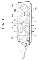
- Fig. 1 is a side view showing the general construction of an embodiment of the invention.
- Fig. 3 is a perspective view showing the engagement section of the image-forming cartridge and the frame.
- Fig. 4 is a perspective view showing the engagement between the frame and the image-forming cartridge.
- Fig. 5 is a perspective view showing the engagement between the LED head and the image-forming cartridge.
- FIg. 6 is a perspective view showing the means for fixing the developing agent tank.
- Fig. 7 is a perspective view showing the state in which the developing agent tank is fixed.
- the electrophotographic printing apparatus of this embodiment comprises an outer housing or main body 101 to which a paper cassette 111, a paper pick-up roller 113, a pair of paper feed rollers 115, a pair of fixing rollers 117, another pair of paper feed rollers 119, a pair of paper eject rollers 121, and an image-forming cartridge 1 are provided. Paper that has been ejected by eject rollers 121 are placed and stacked on a printed paper tray 123.
- the image-forming cartridge 1 is removably mounted in an internal frame 103 fixed in the main body 101.
- a developing agent tank 2 is removably mounted to the cartridge 1 and contains powder developing agent therein.
- a supply roller 3 is provided directly beneath the developing agent tank 2 for supplying the powder developing agent.
- a developing roller 4 is formed of an electrically conductive body and pressed against the supply roller 3.
- a toner blade 5 is pressed with a predetermined pressure against the developing roller 4.
- a photosensitive drum 6 has a photoconductive layer on its surface. The developing roller 4 is in contact with the photosensitive drum.
- a cleaner 7 is in contact with the surface of the photosensitive drum 6.
- a primary charger 17 is parallel with the central axis of the photosensitive drum 6.
- An light-emitting diode (LED) head 9 comprises a multiplicity of light-emitting diodes (LED's) disposed in the direction parallel with the central axis of the photosensitive drum 6 so as to illuminate the photoconductive layer on the surface of the photosensitive drum 6.
- the supply roller 3, the developing roller 4 and the photosensitive drum 6 are supported to the support member of the image-forming cartridge 1, integrally and in parallel with each other, such that they are rotatable.
- the toner blade 5, the cleaner 7, and the primary charger 17 are mounted to the support member of the image-forming cartridge, with a predetermined positional relationship with respect to the developing roller 4 and the photosensitive drum 6.
- the LED head 9 is positioned relative to the supporting member of the image-forming cartridge 1 as illustrated in Fig. 1, by means of a mechanism to be described later.
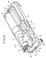
- FIG. 2 Details of the image-forming cartridge 1 is shown in Fig. 2.
- side plates 10 are provided on the right and left of the image-forming cartridge 1. They are fixed to the cartridge case main body part 11, and form the side surfaces of the image-forming cartridge.
- the supply roller 3, the developing roller 4, and the photosensitive drum 6 are rotatably supported, on the inner surfaces of the side plates, via bearings not shown.
- the side plates 10 support the primary charger 17 and the cleaner 7 such that they maintain the positional relationship with respect to the developing roller 4 and the photosensitive drum 6, respectively. That is, the supply roller 3, the developing roller 4, the photosensitive drum 6, the cleaner 7 and the primary charger 17 are positioned and supported by the side plates 10, as illustrated in Fig. 1.
- a developing agent tank-containing case 11a is provided to contact, at its bottom, the cartridge case main body part 11, and coupled to the cartridge case main body part 11, with a predetermined positional relationship with respect to the cartridge case main body 11, by means of the side plates 10.
- the developing agent tank-containing case 11a supports the developing agent tank 2, such that the tank 2 can be mounted and removed. The mechanism for supporting the developing agent tank 2 will later be described in detail.
- the left side plate 10 has a positioning post 13 on the left surface thereof.
- the right side plate 10 also has a similar positioning post, not shown. This positioning post 13 is used for mounting of the image-forming cartridge 1 to the main body 101.
- the side plate 10 has an LED head positioning flat surface 14, on its top, and an LED guiding projection 15 having a truncated cone.
- the positioning flat surface 14 and the guiding projection 15 are provided for accurate positioning with respect to the photosensitive drum 6, and determine the position of the LED head 9 when the LED head 9 is mounted to the image-forming cartridge 1, as described later.
- the image-forming cartridge 1 has a developing agent collecting mechanism, not shown, provided in the image-forming cartridge 1 and moved together with the drive gear of the photosensitive drum 6.
- the developing agent collecting mechanism collects the powder developing agent that has been removed by the cleaner 7 from the surface of the photosensitive drum 6, to the bottom of the image-forming cartridge 1, and conveys the collected powder developing agent to the developing agent tank-containing case by means of a helical conveying means, for the purpose of re-using the powder developing agent.
- the primary charger 17 is fitted on the image-forming cartridge 1.
- a corona discharge wire 8 is made to span in the primary charger 17, in parallel with the central axis of the photosensitive drum 6.
- the primary charger 17 is provided with a discharging wire cleaner 18 which clamps the corona discharging wire 8, and which can slide along the discharge wire 8.
- Fig. 3 shows a fixing means for fixing the image-forming cartridge 1 to the electrophotographic printing apparatus main body 101.
- Each of the supporting members 20 has a U-shaped cut-away 23 opened upward. This cut-away 23 is engaged with the positioning post 13 provided on the side plate of the image-forming cartridge 1 (see Fig. 4).
- the positioning post 13 is coaxial with the photosensitive drum 6.
- the supporting members 20 and the positioning posts 13 support the image-forming cartridge 1 in the vicinity of the photosensitive drum 6.
- the blocks 21a, 21b integrally provided with the frame 103 support a pair of abutment parts 24a, 24b provided on the image-forming cartridge 1.
- the engagement between the blocks 21a, 21b, and the abutment parts 24a, 24b prevents the rotation of the image-forming cartridge 1 accompanying the rotation of the photosensitive drum 6, and maintains the positional relationship with the main body 101.
- Fig. 5 shows the structure for positioning the LED head 9 with respect to the image-forming cartridge 1.
- the frame 103 in which the image-forming cartridge is mounted is provided with an upper lid 26.
- This upper lid 26 is separate from an outer lid, not shown, which is provided at the top of the main body 101.
- the LED head 9 is fixed to the inner surface of the upper lid 26.
- the upper lid 26 protect the printing section of the photosensitive drum 6.
- a guide 27 is formed by bending a rectangular plate 28 having a rectangular perforations 28 (only one at one end being illustrated: other perforations are not seen in Fig. 5.) into the a shape with a channel-like cross section, and fixed at its central portion to the inner surface of the upper lid 26. Pairs of projections 29 (only one at one end being illustrated: others are not seen in the figure) are provided at each end of the LED head 9 and are engaging with the perforations 28.
- a compression spring 30 has one end fixed to the guide 27 and the other end abutting against the LED head 9. The perforations 28 are larger than the projections 29, and the LED head 9 is therefore movable within the range in which the projection 29 is engaged with the perforation 28. In this state, the compression spring 39 biases the LED head 9 away from the upper lid 26.
- a shaft 31 supports the upper lid 26 such that it is rotatable with respect to the frame 103.
- a torsion spring 32 has one end engaged with the frame 103, and the other end engaged with the upper lid 26 to bias the upper lid 26 upward.
- Knobs 33 are slidable along grooves 34 provided in the upper lid 26.
- Each knob 33 has a latch, not shown, which is integrally formed with the knob. This latch is engaged with the jaw portion 35 (Fig. 4) on the frame 103, and fixes the upper lid 26 to the frame 103.
- the frame 103 is also fixed to the main body 101 by an engagement means, not shown.
- a top window 36 is provided in the upper lid 26, directly over the developing agent tank 2.
- the LED head 9 is brought to contact with the image-forming cartridge 1.
- the guiding projections 15 provided on the side plates 10 are engaged with guide perforations, not shown, provided at the predetermined locations on the lower surface of the LED head 9.
- the compression spring 30 presses the LED head 9 against the positioning flat surfaces 14.
- the guiding projections 15 have a shape of the tip of a truncated cone, while the LED head 9 having the guiding perforations is movable within a predetermined range with respect to the guide 27, so the positional relationship between the image-forming cartridge 1 and the LED head 9 is accurately corrected by the guiding projections 15, the guiding perforations, and the positioning flat surfaces 14.
- the outer lid, not shown, at the top of the main body is first opened, and the knobs 1 are moved in the direction of arrow A, and the upper lid 26 is opened, and the image-forming cartridge 1 is then lifted upward.
- the upper lid 26 is kept closed, and the engagement members 12 are manipulated in a manner to be described later, and the developing agent tank 2 is removed, through the top window 36, from the image-forming cartridge 1. In this way, the developing agent tank 2 alone can be removed through the top window 36 without removing the image-forming cartridge 1.
- a similar but opposite procedure is followed when the developing agent tank 2 is mounted.
- a shaft 37 is formed integrally with the engagement member 12.
- a perforation 38 is provided in the side plate of the developing agent tank-containing case 11a.
- the developing agent tank 2 has a side plank 39, an outer cylinder 40 and an inner cylinder 41.
- the side plank is provided with a groove 42.
- An elongated projection 43 is provided on the inner side of the engagement member 12.
- the engagement member 12 is provided with a grip 44.
- a limiter 45 is provided for stopping the rotation of the grip 44 at a predetermined position.
- the engagement member 12 is held to the side plate of the developing agent tank-containing case 11a such that it can rotate.
- the side plank 39 is fixed to the end of the inner cylinder 41 of the developing agent tank 2. With the rotation of the side plank 39, the inner cylinder 41 rotates relative to the outer cylinder 40.
- the developing agent tank-containing case 11a has a semi-circular hollow part 46 which is opened upward to receive the developing agent tank 2.
- the hollow part 46 has, at its bottom, an opening, not shown, which communicates with the developing section, and the developing agent in the developing agent tank is supplied through this opening to the developing section.
- the groove 42 of the side plank 39 is made to assume the same direction as the elongated projection 43 of the engagement member 12, and the developing agent tank 2 is inserted from the above in the direction of arrow B such that the groove 42 engages with the elongated projection 43.
- Fig. 7 shows the state after the insertion.
- the grip 44 is then rotated in the direction of arrow C.
- a groove 44a provided on the inner side of the grip 44 is pushed up onto a step portion 39b provided in front of a tab 39a of the side plank 39, whereby the developing agent tank 2 is pushed downward, and is fixed to tile developing agent tank-containing case 11a.
- the grip 44 When the grip 44 is further rotated in the same direction, the grip 44 is further rotated in the same direction, the grip 44 abuts against the end of the tab 3a to rotate the side plank 39.
- the outer cylinder 40 is fixed and prevented from rotating by a limiter, not shown. Accordingly, after the grip 44 is rotated to the limiter 45, the inner cylinder 41 of the developing agent tank 2 rotates together with the rotation of the side plank 39, and its opening, not shown, is superimposed with an opening, not shown, of the outer cylinder 40 and the developing agent contained therein can flow out.
- the above-mentioned opening is also superimposed with the opening at the bottom of the hollow part 46 of the developing agent tank-containing case 11a, and the developing agent therefore is supplied through the bottom of the containing case 11a to the developing section.
- the grip 44 is rotated in the direction opposite to the arrow C, to the original position, and the tank is pulled upward.
- the developing agent tank 2 and the inner cylinder 44 are rotated in the direction opposite to that described above, and the opening is thereby closed.
- the photosensitive drum and the developing means for supplying the powder developing agent to the surface of the photosensitive drum, and the cleaner for removing the developing agent from the surface of the photosensitive drum are integrally mounted to the support member to form an image-forming cartridge, and the cartridge is removably mounted to the main body of the electrophotographic printing apparatus, and the developing agent tank is removably mounted to the cartridge. It is therefore possible to exchange the cartridge alone or the developing agent tank alone. The cost associated with the use of the apparatus is reduced. Moreover, since the components forming the cartridge, e.g., the photosensitive drum, are not handled by itself, there will be no toner scattering, and the convenience is improved.
- the toner re-using mechanism which is described earlier, is realized.
Landscapes
- Physics & Mathematics (AREA)
- General Physics & Mathematics (AREA)
- Engineering & Computer Science (AREA)
- Computer Vision & Pattern Recognition (AREA)
- Dry Development In Electrophotography (AREA)
- Electrophotography Configuration And Component (AREA)
Claims (6)
- Elektrofotografisches Druckgerät, enthaltend:
eine fotoempfindliche Trommel (6) mit einer fotoleitenden Schicht auf ihrer Oberfläche;
einen Primärlader (17), um die Oberfläche der fotoempfindlichen Trommel (6) gleichförmig aufzuladen;
einen Entwicklungsmitteltank (2) zur Aufnahme von Pulverentwicklungsmittel;
eine Entwicklungseinrichtung (3, 4), um das von dem Entwicklungsmitteltank (2) zugeführte Pulverentwicklungsmittel der Oberfläche der fotoempfindlichen Trommel (6) zuzuführen; und
einen Reiniger (7) zum Entfernen des Pulverentwicklungsmittels von der Oberfläche der fotoempfindlichen Trommel (6);
wobei unter Verwendung des Pulverentwicklungsmittels entsprechend einem auf der fotoempfindlichen Trommel (6) gebildeten elektrostatischen latenten Bild ein sichtbares Bild gebildet wird und das sichtbare Bild auf die Oberfläche eines Druckpapiers übertragen wird, um das Drucken durchzuführen;
wobei die fotoempfindliche Trommel (6), der Primärlader (17), die Entwicklungseinrichtung (3, 4), ein Behälter für den Entwicklungsmitteltank und der Reiniger (7) integral an einem Tragelement montiert sind, um eine Bilderzeugungskassette (1) zu bilden;
dadurch gekennzeichnet, daß
die Kassette abnehmbar an einem Hauptkörper (101) des elektrofotografischen Druckgeräts montiert ist; und
der Entwicklungsmitteltank (2) herausnehmbar im Behälter der Kassette (1) montiert ist;
die Bilderzeugungskassette (1) in einem Rahmen (103) vorgesehen ist;
der Rahmen (103) einen oberen Deckel (26) mit einem Fenster (36) aufweist; und
der Entwicklungsmitteltank (2) im Behälter der Kassette (1) montiert werden kann und durch das Fenster (36) des oberen Deckels (26) hindurch aus dem Behälter der Kassette (1) herausgenommen werden kann, wodurch der Entwicklungsmitteltank (2) am Behälter der Kassette (1) montiert und daraus herausgenommen werden kann, während die Kassette (1) am Körper (101) des elektrofotografschen Druckgeräts montiert ist. - Gerät nach Anspruch 1, wobei
der Entwicklungsmitteltank (2) einen Innenzylinder (41) mit einer Öffnung und einem Außenzylinder (40) mit einer Öffnung aufweist, die sich nicht mit der Öffnung des Innenzylinders (41) überlappt, wenn der Entwicklungsmitteltank (2) nicht in der Bilderzeugungskassette (1) montiert ist; und
der Behälter eine Öffnung hat, die sich mit der Öffnung des Außenzylinders (40) überlappt, wenn der Entwicklungsmitteltank (2) im Behälter montiert ist;
wobei das Gerät ferner eine Einrichtung zum Drehen des Innenzylinders (41) relativ zum Außenzylinder (40) aufweist, so daß die Öffnung des Innenzylinders (41), die Öffnung des Außenzylinders (40) und die Öffnung des Behälters einander überlappen, um eine Zufuhr vom Entwicklungsmitteltank (2) an die Entwicklungseinrichtung (3, 4) zu ermöglichen. - Gerät nach Anspruch 1, das ferner einen Druckkopf (9) zur Bildung eines elektrostatischen latenten Bildes auf der fotoempfindlichen Trommel (6) aufweist, wobei der Druckkopf (9) auf eine solche Weise an dem oberen Deckel (26) montiert ist, daß er relativ zu dem oberen Deckel (26) beweglich ist.
- Gerät nach Anspruch 1, das ferner eine Vorspanneinrichtung (30) aufweist, um den Druckkopf (9) von dem oberen Deckel (26) weg vorzuspannen.
- Gerät nach Anspruch 1, wobei
der Entwicklungsmitteltank (2) einen Innenzylinder (41) mit einer Öffnung und einen Außenzylinder (40) mit einer Öffnung enthält,
wobei der Innenzylinder (41) unabhängig drehbar ist, so daß die Öffnung des Innenzylinders (41) auf die Öffnung des Außenzylinders (40) ausgerichtet werden kann. - Elektrofotografisches Druckgerät, enthaltend:
einen Hauptkörper (101), der eine Vielzahl von Papiertransportwalzen (113, 115, 117, 119, 121) enthält;
einen Rahmen (103), der in dem Hauptkörper (101) des Geräts montiert ist und der eine Öffnung aufweist, die nach oben zeigt;
einen auf dem Rahmen (103) montierten aufmachbaren Deckel (26), der die Öffnung bedeckt und ein Fenster (36) aufweist;
eine abnehmbar an dem Hauptkörper (101) montierte Bilderzeugungskassette (1), die eine fotoempfindliche Trommel (6) mit einer fotoleitenden Schicht auf ihrer Oberfläche und eine Einrichtung (3, 4) enthält, um der fotoempfindlichen Trommel (6) Entwicklungsmittel zuzuführen; und
einen Entwicklungsmitteltank (2), der abnehmbar an der Bilderzeugungskassette (1) montiert ist und der bei geschlossenem Deckel (26) durch das Fenster (36) hindurch herausnehmbar ist.
Applications Claiming Priority (2)
| Application Number | Priority Date | Filing Date | Title |
|---|---|---|---|
| JP25159/90 | 1990-02-06 | ||
| JP2025159A JP2854911B2 (ja) | 1990-02-06 | 1990-02-06 | 画像形成カートリッジ及びこのカートリッジを用いる電子写真印刷装置 |
Publications (3)
| Publication Number | Publication Date |
|---|---|
| EP0441227A2 EP0441227A2 (de) | 1991-08-14 |
| EP0441227A3 EP0441227A3 (en) | 1992-05-27 |
| EP0441227B1 true EP0441227B1 (de) | 1995-05-31 |
Family
ID=12158247
Family Applications (1)
| Application Number | Title | Priority Date | Filing Date |
|---|---|---|---|
| EP91101139A Expired - Lifetime EP0441227B1 (de) | 1990-02-06 | 1991-01-29 | Elektrofotografisches Druckgerät |
Country Status (4)
| Country | Link |
|---|---|
| US (1) | US5184177A (de) |
| EP (1) | EP0441227B1 (de) |
| JP (1) | JP2854911B2 (de) |
| DE (1) | DE69110064T2 (de) |
Families Citing this family (5)
| Publication number | Priority date | Publication date | Assignee | Title |
|---|---|---|---|---|
| GB2273263A (en) * | 1992-12-12 | 1994-06-15 | Bernard David Linsley | Electrographic process cartridge with demountable toner cartridge |
| TW240299B (de) | 1992-12-30 | 1995-02-11 | Ricoh Kk | |
| US5630198A (en) * | 1995-12-28 | 1997-05-13 | Brother Kogyo Kabushiki Kaisha | Toner fillable cartridge having protrusions engageable with a development case shutter |
| US7063399B2 (en) * | 2003-06-25 | 2006-06-20 | Lexmark International, Inc. | Imaging apparatus and method for facilitating printing |
| US20060095280A1 (en) * | 2004-11-03 | 2006-05-04 | Lexmark International, Inc. | Method and apparatus for paying for printing materials in a printer over the usage time of a printer cartridge |
Citations (2)
| Publication number | Priority date | Publication date | Assignee | Title |
|---|---|---|---|---|
| US4757344A (en) * | 1985-07-16 | 1988-07-12 | Ricoh Company, Ltd. | Imaging apparatus with detachable cartridges |
| US4866482A (en) * | 1986-10-24 | 1989-09-12 | Ricoh Company, Ltd. | Image forming device for electrostatic recording apparatus having a slidable replacement holding case |
Family Cites Families (14)
| Publication number | Priority date | Publication date | Assignee | Title |
|---|---|---|---|---|
| US3651838A (en) * | 1970-12-15 | 1972-03-28 | Eastman Kodak Co | Loading mechanism improvement |
| JPS5456436A (en) * | 1977-10-14 | 1979-05-07 | Fuji Xerox Co Ltd | Electrostatic recrder |
| JPS5854392A (ja) * | 1981-09-28 | 1983-03-31 | ヤマハ株式会社 | 楽譜表示装置 |
| JPS5961859A (ja) * | 1982-09-30 | 1984-04-09 | Canon Inc | プロセスキットおよび前記プロセスキットを装着可能な画像形成装置 |
| JPS59147764A (ja) * | 1983-02-15 | 1984-08-24 | Ube Ind Ltd | ダイカスト機における射出方法および装置 |
| FR2587510B1 (fr) * | 1985-09-17 | 1991-01-11 | Canon Kk | Element de support d'image, cartouche de traitement contenant un tel element et appareil de formation d'images |
| JPS6311640A (ja) * | 1986-06-30 | 1988-01-19 | Showa Alum Corp | ヒ−トロ−ラ−用アルミニウム合金 |
| JPH063391Y2 (ja) * | 1986-12-22 | 1994-01-26 | カシオ電子工業株式会社 | 現像装置 |
| DE8705870U1 (de) * | 1987-04-16 | 1987-11-12 | Berolina International Marketing Strategie GmbH, 1000 Berlin | Abdeckung für eine Tonerbehälter-Austrittsöffnung |
| US4954844A (en) * | 1987-12-17 | 1990-09-04 | Konica Corporation | Multicolor image developing device |
| US4974023A (en) * | 1988-06-23 | 1990-11-27 | Sharp Kabushiki Kaisha | Developing device for copier |
| JPH0642850Y2 (ja) * | 1988-06-30 | 1994-11-09 | 沖電気工業株式会社 | 電子写真プリンタ |
| JPH0233168A (ja) * | 1988-07-22 | 1990-02-02 | Konica Corp | 複写機のトナーカートリッジ |
| US4987446A (en) * | 1988-12-15 | 1991-01-22 | Ricoh Company, Ltd. | Process unit cartridge for an electrophotographic apparatus |
-
1990
- 1990-02-06 JP JP2025159A patent/JP2854911B2/ja not_active Expired - Lifetime
-
1991
- 1991-01-29 DE DE69110064T patent/DE69110064T2/de not_active Expired - Lifetime
- 1991-01-29 EP EP91101139A patent/EP0441227B1/de not_active Expired - Lifetime
- 1991-01-31 US US07/648,208 patent/US5184177A/en not_active Expired - Lifetime
Patent Citations (2)
| Publication number | Priority date | Publication date | Assignee | Title |
|---|---|---|---|---|
| US4757344A (en) * | 1985-07-16 | 1988-07-12 | Ricoh Company, Ltd. | Imaging apparatus with detachable cartridges |
| US4866482A (en) * | 1986-10-24 | 1989-09-12 | Ricoh Company, Ltd. | Image forming device for electrostatic recording apparatus having a slidable replacement holding case |
Also Published As
| Publication number | Publication date |
|---|---|
| DE69110064D1 (de) | 1995-07-06 |
| EP0441227A3 (en) | 1992-05-27 |
| US5184177A (en) | 1993-02-02 |
| EP0441227A2 (de) | 1991-08-14 |
| JP2854911B2 (ja) | 1999-02-10 |
| JPH03231257A (ja) | 1991-10-15 |
| DE69110064T2 (de) | 1996-01-25 |
Similar Documents
| Publication | Publication Date | Title |
|---|---|---|
| US5471284A (en) | Image forming apparatus having toner depletion detection feature | |
| JP4292991B2 (ja) | 画像形成装置 | |
| EP1768004B1 (de) | Kartusche, Bilderzeugungsvorrichtung und Verfahren zur Montage und Demontage der Kartusche auf und von einem Hauptgehäuse der Bilderzeugungsvorrichtung | |
| EP0437097B1 (de) | Bilderzeugungsgerät | |
| US5309211A (en) | Process unit having two chambers for storing waste developer | |
| JPH06110263A (ja) | プロセスカートリッジ及び画像形成装置 | |
| KR100327959B1 (ko) | 화상형성장치 및 화상형성장치에서의 특정한 프로세스카트리지만의 수납방법 | |
| JPH10268734A (ja) | カートリッジとその挿入方法、これらを用いた画像形成装置 | |
| JP3263388B2 (ja) | トナーカートリッジおよび画像形成装置 | |
| EP0441227B1 (de) | Elektrofotografisches Druckgerät | |
| JP4621327B2 (ja) | 画像形成装置 | |
| CN110967954A (zh) | 转印带单元和图像形成设备 | |
| EP0621515A2 (de) | Bilderzeugungsgerät mit einem lichtempfindlichen Teil | |
| JP2898332B2 (ja) | 電子写真装置 | |
| JPH0833704B2 (ja) | プロセスカートリッジ及び画像形成装置 | |
| KR100565088B1 (ko) | 급지 카세트 및 이를 구비한 화상형성장치 | |
| JP2622580B2 (ja) | 画像形成装置及びプロセスカートリッジ | |
| US7539439B2 (en) | Image carrier toner unit and image forming apparatus | |
| JPH02253287A (ja) | 感光体ユニット | |
| JP3190393B2 (ja) | 給紙装置の給紙カセット | |
| JPH0626927Y2 (ja) | 画像形成装置 | |
| JP2002072811A (ja) | 電子写真装置 | |
| JPS63298268A (ja) | 作像装置 | |
| JPH066365Y2 (ja) | 画像形成装置 | |
| JPH0250021B2 (de) |
Legal Events
| Date | Code | Title | Description |
|---|---|---|---|
| PUAI | Public reference made under article 153(3) epc to a published international application that has entered the european phase |
Free format text: ORIGINAL CODE: 0009012 |
|
| AK | Designated contracting states |
Kind code of ref document: A2 Designated state(s): DE FR GB |
|
| PUAL | Search report despatched |
Free format text: ORIGINAL CODE: 0009013 |
|
| AK | Designated contracting states |
Kind code of ref document: A3 Designated state(s): DE FR GB |
|
| 17P | Request for examination filed |
Effective date: 19920921 |
|
| 17Q | First examination report despatched |
Effective date: 19940321 |
|
| GRAA | (expected) grant |
Free format text: ORIGINAL CODE: 0009210 |
|
| AK | Designated contracting states |
Kind code of ref document: B1 Designated state(s): DE FR GB |
|
| ET | Fr: translation filed | ||
| REF | Corresponds to: |
Ref document number: 69110064 Country of ref document: DE Date of ref document: 19950706 |
|
| PLBE | No opposition filed within time limit |
Free format text: ORIGINAL CODE: 0009261 |
|
| STAA | Information on the status of an ep patent application or granted ep patent |
Free format text: STATUS: NO OPPOSITION FILED WITHIN TIME LIMIT |
|
| 26N | No opposition filed | ||
| REG | Reference to a national code |
Ref country code: GB Ref legal event code: IF02 |
|
| PGFP | Annual fee paid to national office [announced via postgrant information from national office to epo] |
Ref country code: FR Payment date: 20100208 Year of fee payment: 20 |
|
| PGFP | Annual fee paid to national office [announced via postgrant information from national office to epo] |
Ref country code: GB Payment date: 20100202 Year of fee payment: 20 Ref country code: DE Payment date: 20100121 Year of fee payment: 20 |
|
| REG | Reference to a national code |
Ref country code: GB Ref legal event code: PE20 Expiry date: 20110128 |
|
| PG25 | Lapsed in a contracting state [announced via postgrant information from national office to epo] |
Ref country code: GB Free format text: LAPSE BECAUSE OF EXPIRATION OF PROTECTION Effective date: 20110128 |
|
| PG25 | Lapsed in a contracting state [announced via postgrant information from national office to epo] |
Ref country code: DE Free format text: LAPSE BECAUSE OF EXPIRATION OF PROTECTION Effective date: 20110129 |