EP0441291A1 - Dispositif et appareil pour tester la tension de tenue - Google Patents
Dispositif et appareil pour tester la tension de tenue Download PDFInfo
- Publication number
- EP0441291A1 EP0441291A1 EP91101453A EP91101453A EP0441291A1 EP 0441291 A1 EP0441291 A1 EP 0441291A1 EP 91101453 A EP91101453 A EP 91101453A EP 91101453 A EP91101453 A EP 91101453A EP 0441291 A1 EP0441291 A1 EP 0441291A1
- Authority
- EP
- European Patent Office
- Prior art keywords
- voltage
- withstand
- work
- conductor
- discharge
- Prior art date
- Legal status (The legal status is an assumption and is not a legal conclusion. Google has not performed a legal analysis and makes no representation as to the accuracy of the status listed.)
- Granted
Links
- 238000012360 testing method Methods 0.000 title claims abstract description 22
- 239000004020 conductor Substances 0.000 claims abstract description 44
- 238000009413 insulation Methods 0.000 claims abstract description 10
- 230000001360 synchronised effect Effects 0.000 claims description 7
- 239000013307 optical fiber Substances 0.000 claims description 4
- 238000010998 test method Methods 0.000 claims description 3
- 238000000034 method Methods 0.000 abstract description 7
- 230000008878 coupling Effects 0.000 description 4
- 238000010168 coupling process Methods 0.000 description 4
- 238000005859 coupling reaction Methods 0.000 description 4
- 239000011347 resin Substances 0.000 description 4
- 229920005989 resin Polymers 0.000 description 4
- 238000001514 detection method Methods 0.000 description 3
- 229910052754 neon Inorganic materials 0.000 description 3
- GKAOGPIIYCISHV-UHFFFAOYSA-N neon atom Chemical compound [Ne] GKAOGPIIYCISHV-UHFFFAOYSA-N 0.000 description 3
- 238000010586 diagram Methods 0.000 description 2
- 230000003287 optical effect Effects 0.000 description 2
- 239000011324 bead Substances 0.000 description 1
- 239000011248 coating agent Substances 0.000 description 1
- 238000000576 coating method Methods 0.000 description 1
- 238000007796 conventional method Methods 0.000 description 1
- 230000035945 sensitivity Effects 0.000 description 1
Images

Classifications
-
- G—PHYSICS
- G01—MEASURING; TESTING
- G01R—MEASURING ELECTRIC VARIABLES; MEASURING MAGNETIC VARIABLES
- G01R31/00—Arrangements for testing electric properties; Arrangements for locating electric faults; Arrangements for electrical testing characterised by what is being tested not provided for elsewhere
- G01R31/12—Testing dielectric strength or breakdown voltage ; Testing or monitoring effectiveness or level of insulation, e.g. of a cable or of an apparatus, for example using partial discharge measurements; Electrostatic testing
Definitions
- the present invention relates to a method of testing a withstand-voltage of a work including a core conductor coated for insulation and a withstand-voltage testing apparatus employed in this method.
- Figs. 1 to 3 show a known high withstand-voltage testing apparatus for testing a high withstand-voltage of a work 1 in which a core conductor 2 is coated for insulation with an insulating member 3 made of resin, etc.
- the work 1 is enclosed by a grounded conductor 4.
- a three-pole discharge electrode 5 is constituted by a positive pole 5a, a negative pole 5b and a floating pole 5c.
- the positive pole 5a is connected to the core conductor 2, while the negative pole 5b is connected to the grounded conductor 4.
- a high-voltage pulse generator 6 is constituted by a high-voltage generator 6a and an oscillator 6b.
- a resistor R for detecting leakage current of the work 1 is inserted between the grounded conductor 4 and earth.
- a voltmeter 7 is provided for detecting voltage of the resistor R.
- a resinous coating 10 of the high-voltage cable 9 has joints and pin holes.
- a high withstand-voltage test is performed mainly at coupling portions 10a and 10b of the high-voltage cable 9, where leakage current is likely to be produced. Accordingly, a distal end 8' of the high-voltage cable 9 adjacent to the spark plug 8 is supported by a coupling jig 11c.
- the coupling portions 10a and 10b are supported by grounding jigs 11a and 11b, respectively and further are, respectively, surrounded by metallic beads 4a and 4b strung on threads and acting as the grounded conductor 4 so as to be grounded.
- leakage current in the work 1 is detected by the resistor R or the neon lamp.
- the resistor R or the neon lamp is an electric detector and therefore, is affected by electrical noises. Accordingly, if electrical noises become extremely large, it is necessary to raise impedance between the detection system and the decision system. As a result, such a drawback is incurred that the decision system is susceptible to electrical noises and thus, functions unstably.
- such a phenomenon may happen in the known apparatus that even in the case where the work 1 has proper withstand-voltage and discharge is generated at the discharge electrode 5, leakage current due to moisture, etc. is detected at the work 1, thereby resulting in erroneous decision in the high withstand-voltage test.
- the known high withstand-voltage testing apparatus has been disadvantageous in that erroneous decision is likely to be made due to long response time from detection to decision or drop of detection sensitivity.
- an essential object of the present invention is to provide a method of and an apparatus for testing a withstand-voltage of a work having a core conductor coated for insulation, which eliminate the disadvantages inherent in conventional methods and apparatuses of this kind.
- a method of testing a withstand-voltage of a work having a core conductor coated for insulation with an insulating member comprises the steps of: enclosing the insulating member by a grounded conductor; providing first and second discharge electrodes for the core conductor and the grounded electrode, respectively so as to connect the first and second discharge electrodes between the core conductor and the grounded conductor; applying high-voltage pulses to the core conductor so as to detect discharge beams generated in a gap between the first and second discharge electrodes; and judging whether or not the insulating member has a proper withstand-voltage.
- generation of leakage current of the work is detected by directly detecting presence or absence of the pulsed discharge beams generated at the gap of the discharge electrodes, whereby it becomes possible to judge whether or not the work has proper dielectric strength.
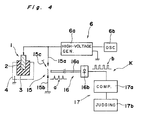
- a withstand-voltage testing method and a withstand-voltage testing apparatus K employed in this method, according to one embodiment of the present invention are described with reference to Fig. 4.
- a work 1 has a core conductor 2 which is coated for insulation with an insulating member 3 made of resin, etc.
- the work 1 is enclosed by a grounded conductor 4.
- a high-voltage pulse generator 6 is constituted by a high-voltage generator 6a and an oscillator 6b.
- the discharge electrode 5 of the prior art apparatus is replaced by a discharge electrode 15 constituted by a positive pole 15a, a negative pole 15b and a floating pole 15c.
- the positive pole 15a is connected to the core conductor 2, while the negative pole 15b is connected to the grounded conductor 4.
- the apparatus K further includes a light receiving portion 16 and a decision portion 17.
- an optical detecting system including the discharge electrode 15, the light receiving portion 16 and the decision portion 17 is employed in place of the prior art electric detecting system (Figs. 1 and 2) including the resistor R, the voltmeter 7, etc.
- the light receiving portion 16 includes an optical fiber 16a drawn from vicinity of a gap of the discharge electrode 15 and a high-speed photo diode 16b.
- the photo diode 16b is connected to an output of the optical fiber 16a so as to generate a reverse voltage upon reception of light.
- the decision portion 17 includes a synchronous comparator 17a and a judging portion 17b.
- the synchronous comparator 17a is connected to an output of the photo diode 16b so as to synchronously compare high-voltage pulses applied to the discharge electrode 15 and pulsed discharge beams at the discharge electrode 15.
- the judging portion 17b is connected to an output of the synchronous comparator 17a and detects presence or absence of leakage current in the work 1 by detecting presence or absence of the pulsed discharge beams synchronous with the high-voltage pulses so as to judge whether or not the work 1 has proper withstand-voltage.
- high-voltage pulses of 50-100 Hz and about 25 KV are initially generated by the high-voltage pulse generator 6 so as to produce pulsed discharge beams in the gap of the discharge electrode 15.
- only pulse beams a of the discharge beams are received by the optical fiber 16a so as to be electrically converted into pulse waves b by the photo diode 16b such that the pulse waves b are outputted from the light receiving portion 16.
- the pulse waves b are detected synchronously with the high-voltage pulses by the decision portion 17. If there is no leakage current in the work 1, the pulse waves b are continuously generated. Thus, in this case, the decision portion 17 judges that the work has proper withstand-voltage.
- the decision portion 17 is capable of judging that the work 1 has improper withstand-voltage. Accordingly, the decision portion 17 has high decision accuracy. For decision accuracy in practical use, the decision portion 17 is required to judge that the work 1 has improper withstand-voltage when two or more of the pulse waves b have disappeared continuously.
- the light receiving portion 16 desirably includes the high-speed photo diode 16b. However, the high-speed photo diode 16b may be replaced by a photo detector having a short response time.
- the discharge beams generated at the discharge electrode are directly detected such that leakage current is detected based on presence or absence of generation of the discharge beams, whereby it is judged whether or not the high-voltage cable has proper withstand-voltage. Therefore, in accordance with the present invention, the electrically independent optical system detects leakage current of the work and therefore, is not affected by electrical noises, thus, resulting in improvement of decision accuracy of the withstand-voltage test.
Landscapes
- Physics & Mathematics (AREA)
- General Physics & Mathematics (AREA)
- Testing Relating To Insulation (AREA)
Applications Claiming Priority (2)
| Application Number | Priority Date | Filing Date | Title |
|---|---|---|---|
| JP2026573A JPH0830728B2 (ja) | 1990-02-05 | 1990-02-05 | 耐圧検査方法及び装置 |
| JP26573/90 | 1990-02-05 |
Publications (2)
| Publication Number | Publication Date |
|---|---|
| EP0441291A1 true EP0441291A1 (fr) | 1991-08-14 |
| EP0441291B1 EP0441291B1 (fr) | 1995-08-02 |
Family
ID=12197297
Family Applications (1)
| Application Number | Title | Priority Date | Filing Date |
|---|---|---|---|
| EP91101453A Expired - Lifetime EP0441291B1 (fr) | 1990-02-05 | 1991-02-04 | Dispositif et appareil pour tester la tension de tenue |
Country Status (4)
| Country | Link |
|---|---|
| US (1) | US5128618A (fr) |
| EP (1) | EP0441291B1 (fr) |
| JP (1) | JPH0830728B2 (fr) |
| DE (1) | DE69111626T2 (fr) |
Cited By (4)
| Publication number | Priority date | Publication date | Assignee | Title |
|---|---|---|---|---|
| DE4208533B4 (de) * | 1991-03-18 | 2006-08-03 | Denso Corp., Kariya | Vorrichtung und Verfahren zur Erfassung eines mechanischen Defekts in einem elektrischen fehlerhaft arbeitenden Isolator |
| CN104020399A (zh) * | 2014-06-12 | 2014-09-03 | 国家电网公司 | 750kV绝缘工器具分段交流耐压试验设施 |
| CN104020400A (zh) * | 2014-06-12 | 2014-09-03 | 国家电网公司 | 750kV绝缘工器具分段交流耐压试验方法 |
| CN113533920A (zh) * | 2021-09-13 | 2021-10-22 | 广东电网有限责任公司中山供电局 | 一种绝缘隔板自动耐压试验装置及方法 |
Families Citing this family (13)
| Publication number | Priority date | Publication date | Assignee | Title |
|---|---|---|---|---|
| JPH07151811A (ja) * | 1993-12-01 | 1995-06-16 | Sumitomo Wiring Syst Ltd | 耐電圧試験装置 |
| US5614914A (en) * | 1994-09-06 | 1997-03-25 | Interdigital Technology Corporation | Wireless telephone distribution system with time and space diversity transmission for determining receiver location |
| US7087061B2 (en) * | 2002-03-12 | 2006-08-08 | Lithotech Medical Ltd | Method for intracorporeal lithotripsy fragmentation and apparatus for its implementation |
| JP4947986B2 (ja) * | 2006-02-02 | 2012-06-06 | 株式会社アドバンテスト | 試験装置および試験方法 |
| CN101210950B (zh) * | 2006-12-27 | 2011-01-26 | 鸿富锦精密工业(深圳)有限公司 | 电子元件耐压测试设备 |
| JP2010204067A (ja) * | 2009-03-06 | 2010-09-16 | Ehime Univ | 部分放電発生回数測定装置 |
| RU2506601C1 (ru) * | 2012-06-18 | 2014-02-10 | Федеральное государственное бюджетное образовательное учреждение высшего профессионального образования "Томский государственный университет систем управления и радиоэлектроники" | Способ контроля и ремонта изоляции проводов |
| RU2506602C1 (ru) * | 2012-06-21 | 2014-02-10 | Федеральное государственное бюджетное образовательное учреждение высшего профессионального образования Томский государственный университет систем управления и радиоэлектроники | Способ контроля и ремонта изоляции проводов |
| RU2642499C1 (ru) * | 2016-09-19 | 2018-01-25 | Федеральное государственное бюджетное образовательное учреждение высшего профессионального образования "Томский государственный университет систем управления и радиоэлектроники" | Способ контроля и ремонта изоляции проводов |
| RU2662249C1 (ru) * | 2017-04-24 | 2018-07-25 | Федеральное государственное бюджетное образовательное учреждение высшего образования "Томский государственный университет систем управления и радиоэлектроники" (ТУСУР) | Устройство для контроля толщины изоляции микропровода |
| RU191788U1 (ru) * | 2019-05-16 | 2019-08-21 | Евгений Николаевич Коптяев | Датчик уровня жидких сред с удвоенной чувствительностью |
| CN110676601B (zh) * | 2019-11-13 | 2025-04-22 | 天津斌德鑫力电子科技有限公司 | 一种耐压测试连接设备 |
| CN116430187B (zh) * | 2023-06-13 | 2023-08-15 | 深圳市微特精密科技股份有限公司 | 自动化耐压测试设备 |
Citations (5)
| Publication number | Priority date | Publication date | Assignee | Title |
|---|---|---|---|---|
| DE559270C (de) * | 1930-01-16 | 1932-09-17 | Hans Heyne Dipl Ing | Messanordnung zur Bestimmung von Spannungen |
| DE928784C (de) * | 1941-01-31 | 1955-06-10 | Siemens Ag | Verfahren zur Pruefung der Isolation elektrischer Leitungen und Kabel |
| US3135915A (en) * | 1959-09-08 | 1964-06-02 | Gen Electric | Method of determining the condition of electrical insulation including the presence of polar materials therein and thereon using d.c. voltage |
| DE2851537A1 (de) * | 1978-11-29 | 1980-06-12 | Licentia Gmbh | Schutzeinrichtung mit funkenstrecke und schutzwiderstand |
| DE3031517A1 (de) * | 1979-09-04 | 1981-04-02 | ASEA AB, Västerås | Anordnung zur erfassung von lichtboegen und anderer lichtsignale |
Family Cites Families (6)
| Publication number | Priority date | Publication date | Assignee | Title |
|---|---|---|---|---|
| US3421076A (en) * | 1966-10-03 | 1969-01-07 | Okonite Co | Cable scanning method and apparatus wherein corona discharge is detected only at approximately peak values of an applied voltage |
| US3899735A (en) * | 1971-03-22 | 1975-08-12 | Edouard Singer | Voltage detector for detecting AC voltages |
| US3991367A (en) * | 1976-01-20 | 1976-11-09 | The United States Of America As Represented By The Secretary Of The Interior | Detection of potential on high-voltage transmission lines |
| FR2388279A1 (fr) * | 1977-04-19 | 1978-11-17 | Onera (Off Nat Aerospatiale) | Procede et appareil pour la mesure a distance de l'intensite d'un courant electrique |
| JPS54158278A (en) * | 1978-06-02 | 1979-12-13 | Hitachi Cable Ltd | Corona detection of insulator |
| JP5316296B2 (ja) | 2009-08-05 | 2013-10-16 | 株式会社デンソーウェーブ | ロボットのアームカバー |
-
1990
- 1990-02-05 JP JP2026573A patent/JPH0830728B2/ja not_active Expired - Lifetime
-
1991
- 1991-01-30 US US07/647,970 patent/US5128618A/en not_active Expired - Fee Related
- 1991-02-04 EP EP91101453A patent/EP0441291B1/fr not_active Expired - Lifetime
- 1991-02-04 DE DE69111626T patent/DE69111626T2/de not_active Expired - Fee Related
Patent Citations (5)
| Publication number | Priority date | Publication date | Assignee | Title |
|---|---|---|---|---|
| DE559270C (de) * | 1930-01-16 | 1932-09-17 | Hans Heyne Dipl Ing | Messanordnung zur Bestimmung von Spannungen |
| DE928784C (de) * | 1941-01-31 | 1955-06-10 | Siemens Ag | Verfahren zur Pruefung der Isolation elektrischer Leitungen und Kabel |
| US3135915A (en) * | 1959-09-08 | 1964-06-02 | Gen Electric | Method of determining the condition of electrical insulation including the presence of polar materials therein and thereon using d.c. voltage |
| DE2851537A1 (de) * | 1978-11-29 | 1980-06-12 | Licentia Gmbh | Schutzeinrichtung mit funkenstrecke und schutzwiderstand |
| DE3031517A1 (de) * | 1979-09-04 | 1981-04-02 | ASEA AB, Västerås | Anordnung zur erfassung von lichtboegen und anderer lichtsignale |
Cited By (6)
| Publication number | Priority date | Publication date | Assignee | Title |
|---|---|---|---|---|
| DE4208533B4 (de) * | 1991-03-18 | 2006-08-03 | Denso Corp., Kariya | Vorrichtung und Verfahren zur Erfassung eines mechanischen Defekts in einem elektrischen fehlerhaft arbeitenden Isolator |
| CN104020399A (zh) * | 2014-06-12 | 2014-09-03 | 国家电网公司 | 750kV绝缘工器具分段交流耐压试验设施 |
| CN104020400A (zh) * | 2014-06-12 | 2014-09-03 | 国家电网公司 | 750kV绝缘工器具分段交流耐压试验方法 |
| CN104020400B (zh) * | 2014-06-12 | 2016-09-28 | 国家电网公司 | 750kV绝缘工器具分段交流耐压试验方法 |
| CN113533920A (zh) * | 2021-09-13 | 2021-10-22 | 广东电网有限责任公司中山供电局 | 一种绝缘隔板自动耐压试验装置及方法 |
| CN113533920B (zh) * | 2021-09-13 | 2022-01-25 | 广东电网有限责任公司中山供电局 | 一种绝缘隔板自动耐压试验装置及方法 |
Also Published As
| Publication number | Publication date |
|---|---|
| DE69111626T2 (de) | 1996-01-25 |
| US5128618A (en) | 1992-07-07 |
| EP0441291B1 (fr) | 1995-08-02 |
| JPH0830728B2 (ja) | 1996-03-27 |
| DE69111626D1 (de) | 1995-09-07 |
| JPH03229170A (ja) | 1991-10-11 |
Similar Documents
| Publication | Publication Date | Title |
|---|---|---|
| US5128618A (en) | Withstand-voltage testing method and apparatus | |
| US5132629A (en) | Apparatus for testing the insulation of an electrical conductor passing through an electrode | |
| EP0541843A1 (fr) | Système de présence et d'identification de fil | |
| CA2102880A1 (fr) | Systeme utilisant un courant induit pour tester sans contact les reseaux de cablage | |
| US4891597A (en) | Synchronous detection and location of insulation defects | |
| US6351114B1 (en) | High frequency current detecting apparatus | |
| EP0656543B1 (fr) | Appareil de test de la rigidité diélectrique | |
| EP0367379A1 (fr) | Dispositif avec une source d'ions allongée et procédé pour détecter des défauts d'isolation | |
| JP2002323533A (ja) | 電力機器の部分放電試験方法 | |
| JP2608925B2 (ja) | 電力ケーブルの部分放電検出方法 | |
| JP3272231B2 (ja) | 地絡電圧サージ検出方法および装置 | |
| JPH03150474A (ja) | 除電装置の検査器 | |
| JPH07260870A (ja) | 電力ケーブル直流漏れ電流の測定法 | |
| JP2960782B2 (ja) | 部分放電測定方法 | |
| JP3231557B2 (ja) | 部分放電測定用アダプタ及び部分放電測定方法 | |
| JPS63292077A (ja) | ケ−ブルの部分放電発生位置の標定方法 | |
| CN115598464A (zh) | 一种电缆末端高低压电路的检测和修复装置及其方法 | |
| JPH06308189A (ja) | ケーブルの部分放電検出方法 | |
| JPH0666872A (ja) | ケーブル導体断線位置検出方法 | |
| JPH0917550A (ja) | 高圧ケーブル装置 | |
| JPH063404A (ja) | 送電用ケーブル接続装置の部分放電測定装置 | |
| JPH1026649A (ja) | ガス絶縁機器の部分放電検出方法 | |
| JPS60146161A (ja) | 電気絶縁機器の異常検出装置 | |
| JPH06331684A (ja) | コンデンサ形計器用変圧器の内部部分放電検出方法 | |
| JPH03123876A (ja) | ケーブルの絶縁破壊点判定方法 |
Legal Events
| Date | Code | Title | Description |
|---|---|---|---|
| PUAI | Public reference made under article 153(3) epc to a published international application that has entered the european phase |
Free format text: ORIGINAL CODE: 0009012 |
|
| AK | Designated contracting states |
Kind code of ref document: A1 Designated state(s): DE FR GB |
|
| 17P | Request for examination filed |
Effective date: 19920115 |
|
| 17Q | First examination report despatched |
Effective date: 19930609 |
|
| GRAA | (expected) grant |
Free format text: ORIGINAL CODE: 0009210 |
|
| AK | Designated contracting states |
Kind code of ref document: B1 Designated state(s): DE FR GB |
|
| REF | Corresponds to: |
Ref document number: 69111626 Country of ref document: DE Date of ref document: 19950907 |
|
| ET | Fr: translation filed | ||
| PLBE | No opposition filed within time limit |
Free format text: ORIGINAL CODE: 0009261 |
|
| STAA | Information on the status of an ep patent application or granted ep patent |
Free format text: STATUS: NO OPPOSITION FILED WITHIN TIME LIMIT |
|
| 26N | No opposition filed | ||
| PGFP | Annual fee paid to national office [announced via postgrant information from national office to epo] |
Ref country code: GB Payment date: 20000202 Year of fee payment: 10 |
|
| PG25 | Lapsed in a contracting state [announced via postgrant information from national office to epo] |
Ref country code: GB Free format text: LAPSE BECAUSE OF NON-PAYMENT OF DUE FEES Effective date: 20010204 |
|
| PGFP | Annual fee paid to national office [announced via postgrant information from national office to epo] |
Ref country code: FR Payment date: 20010213 Year of fee payment: 11 |
|
| GBPC | Gb: european patent ceased through non-payment of renewal fee |
Effective date: 20010204 |
|
| PGFP | Annual fee paid to national office [announced via postgrant information from national office to epo] |
Ref country code: DE Payment date: 20020227 Year of fee payment: 12 |
|
| PG25 | Lapsed in a contracting state [announced via postgrant information from national office to epo] |
Ref country code: FR Free format text: LAPSE BECAUSE OF NON-PAYMENT OF DUE FEES Effective date: 20021031 |
|
| REG | Reference to a national code |
Ref country code: FR Ref legal event code: ST |
|
| PG25 | Lapsed in a contracting state [announced via postgrant information from national office to epo] |
Ref country code: DE Free format text: LAPSE BECAUSE OF NON-PAYMENT OF DUE FEES Effective date: 20030902 |