EP0441293A1 - Gekühlter Hohlleiter - Google Patents
Gekühlter Hohlleiter Download PDFInfo
- Publication number
- EP0441293A1 EP0441293A1 EP91101456A EP91101456A EP0441293A1 EP 0441293 A1 EP0441293 A1 EP 0441293A1 EP 91101456 A EP91101456 A EP 91101456A EP 91101456 A EP91101456 A EP 91101456A EP 0441293 A1 EP0441293 A1 EP 0441293A1
- Authority
- EP
- European Patent Office
- Prior art keywords
- waveguide
- cannula
- termination
- envelope
- cooled
- Prior art date
- Legal status (The legal status is an assumption and is not a legal conclusion. Google has not performed a legal analysis and makes no representation as to the accuracy of the status listed.)
- Withdrawn
Links
- 239000002826 coolant Substances 0.000 claims abstract description 7
- 239000011810 insulating material Substances 0.000 claims abstract description 5
- 125000006850 spacer group Chemical group 0.000 claims abstract description 5
- 238000007789 sealing Methods 0.000 claims description 14
- 241001631457 Cannula Species 0.000 claims description 8
- 239000003507 refrigerant Substances 0.000 claims description 4
- 230000000694 effects Effects 0.000 abstract description 2
- 239000012530 fluid Substances 0.000 abstract description 2
- 230000005540 biological transmission Effects 0.000 abstract 2
- 239000007789 gas Substances 0.000 description 8
- IJGRMHOSHXDMSA-UHFFFAOYSA-N Atomic nitrogen Chemical compound N#N IJGRMHOSHXDMSA-UHFFFAOYSA-N 0.000 description 6
- 239000007788 liquid Substances 0.000 description 6
- 238000001816 cooling Methods 0.000 description 5
- 239000000463 material Substances 0.000 description 4
- 229910052782 aluminium Inorganic materials 0.000 description 3
- XAGFODPZIPBFFR-UHFFFAOYSA-N aluminium Chemical compound [Al] XAGFODPZIPBFFR-UHFFFAOYSA-N 0.000 description 3
- 238000009413 insulation Methods 0.000 description 3
- 229910052757 nitrogen Inorganic materials 0.000 description 3
- 229910052751 metal Inorganic materials 0.000 description 2
- 239000002184 metal Substances 0.000 description 2
- UFHFLCQGNIYNRP-UHFFFAOYSA-N Hydrogen Chemical compound [H][H] UFHFLCQGNIYNRP-UHFFFAOYSA-N 0.000 description 1
- 208000029152 Small face Diseases 0.000 description 1
- 239000002131 composite material Substances 0.000 description 1
- 239000004020 conductor Substances 0.000 description 1
- 239000012809 cooling fluid Substances 0.000 description 1
- 230000005684 electric field Effects 0.000 description 1
- 239000001257 hydrogen Substances 0.000 description 1
- 229910052739 hydrogen Inorganic materials 0.000 description 1
- 238000009434 installation Methods 0.000 description 1
- 238000002955 isolation Methods 0.000 description 1
Images
Classifications
-
- H—ELECTRICITY
- H01—ELECTRIC ELEMENTS
- H01P—WAVEGUIDES; RESONATORS, LINES, OR OTHER DEVICES OF THE WAVEGUIDE TYPE
- H01P3/00—Waveguides; Transmission lines of the waveguide type
- H01P3/12—Hollow waveguides
-
- H—ELECTRICITY
- H01—ELECTRIC ELEMENTS
- H01P—WAVEGUIDES; RESONATORS, LINES, OR OTHER DEVICES OF THE WAVEGUIDE TYPE
- H01P1/00—Auxiliary devices
- H01P1/30—Auxiliary devices for compensation of, or protection against, temperature or moisture effects ; for improving power handling capability
Definitions
- the invention relates to the cooling of waveguides.
- the cooling of the microwave waveguides is necessary when it is desired to obtain a significant reduction in the line losses.
- a rectangular X-band waveguide (10 GHz) made of aluminum has linear losses of 12 dB / 100m at 20 ° C. These losses fall to 3.2 dB / 100m at the temperature of liquid nitrogen, and to 0.4 dB / 100m at the temperature of liquid hydrogen.
- the superconductive properties of certain materials may also make it possible to obtain, at microwave frequencies, a notable reduction in the resistivity of the conductive outer sheath constituting the waveguide and therefore linear losses.
- the cooling is obtained by circulation of liquid nitrogen in a sheath, independent of the radioelectric structure to be cooled and surrounding said structure.
- Such devices are complicated and difficult to implement.
- the present invention aims to cool the waveguides in a simpler and less expensive way than the devices used.
- the subject of the invention is a cooled waveguide, provided with sealing windows at each end, characterized in that it is cooled by a cooling fluid circulating inside the waveguide which comprises in this case effect an inlet cannula and an outlet cannula, that the cannulas are each arranged at an opposite end of the waveguide, and that each cannula is located in a non-disturbing area of the radio wave propagation of the waveguide.
- This can be of elliptical, oval, circular or square cross section.
- it is preferably of rectangular section, with two large faces, and the cannulas are each arranged on a large face.
- each cannula is located near a sealing window.
- the waveguide is surrounded by an envelope from which it is separated by spacers providing a space between the waveguide and the envelope.
- the space between the envelope and the waveguide is filled with a thermal insulating material.
- the space between the envelope and the waveguide is under vacuum, so as to ensure thermal insulation.
- each cannula is fixed to a termination which covers the waveguide at the end thereof, said termination being provided with a sealing window and the waveguide having an opening opposite of the cannula, to allow the circulation of the coolant in the waveguide.
- each cannula is fixed to a termination provided with a sealing window, said termination coming to cover the waveguide at the end thereof, the waveguide having an opening opposite the cannula to allow the circulation of the coolant in the waveguide, and the envelope being fixed in leaktight manner at the termination.
- the refrigerant fluid is a liquefied gas.
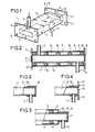
- FIG. 1 represents a rectangular waveguide having a small face 1 and a large face 2, and closed at each end by a sealing window 5, 6 of any known type; the waveguide ends on each side with a connection flange 11; it has on each of its large faces 2 a cannula 3, 4 for a circulation of coolant inside the waveguide.
- These cannulas are preferably arranged at each end of the waveguide, in a non-disturbing zone of the waveguide, so as not to disturb the radioelectric propagation in the waveguide.
- the cannulas are arranged along the axis XX 'of each large face 2.
- the waveguide cooling device here consists, in its simplest form, of the two cannulas 3 and 4, the waveguide not being limited to the rectangular structure shown by way of example, but can be of any type, square, rectangular, elliptical, circular or oval.
- the refrigerant is advantageously a liquefied gas.
- the cannulas 3 and 4 of Figure 1 are obviously connected to a liquefied gas installation; it is possible, for example, to use a tank of liquefied gas to which the cannula 3, for entering the liquefied gas, is connected, the outlet cannula 4 being for example in the open air, the liquefied gas escaping through the cannula 4 obviously with a very low flow.
- the liquid gas will circulate slowly in the waveguide.
- FIG. 2 represents an alternative embodiment of a cooled waveguide of the invention.
- the waveguide of Figure 1 for example, is isolated from the outside by an envelope 7, of the same shape as the waveguide and slightly larger than the latter; spacers 8 make it possible to provide a space 9 between the envelope and the guide.
- the envelope 7 is for example metallic or plastic or composite.
- the spacers 8 are constituted for example by a spiral rod, preferably made of thermal insulating material.
- the connection flanges 11 are pierced with junction holes 13 with a flange of the same type.
- the space 9 between the envelope 7 and the waveguide is for example filled with a thermal insulating material; it is also possible to create a vacuum in said space to limit the loss of calories and thus optimize the thermal insulation.
- FIG. 3 represents a termination of the waveguide of the invention in the simplest embodiment illustrated in FIG. 1.
- the termination consists of a sleeve 10, a sealing window 6 and a cannula 4.
- the sealing window is fixed, in known manner, to one end of the sleeve 10 of section slightly larger than that of the waveguide, the end of which it covers.
- the cannula 4 is fixed in the middle of the large face of the sleeve, in the case of a waveguide rectangular, and comes opposite an opening made in the long face of the waveguide. Obviously the sleeve is tightly fixed on the waveguide.
- FIG. 4 represents an alternative embodiment of the termination of FIG. 3.
- the termination is a conventional flange 11 provided with a sealing window 6 and a cannula 4 on the large face of the sleeve 12 of the flange which has holes 13 for connection with a flange likewise type.
- the cannula 4 comes a look of an opening in the large face of the waveguide when the flange covers the end of said waveguide. Obviously, the sleeve 12 is tightly fixed on the waveguide.
- FIG. 5 represents an alternative embodiment of a termination in the case of the cooled waveguide of FIG. 2.
- the termination consists for example of a sleeve 10 and a sealing window 6, as in FIG. 3, as well as by a shoulder 14, perpendicular to the sleeve 10 and situated opposite the sealing window 6.
- the envelope 7, FIG. 2 is fixed to this shoulder 14, in a sealed manner, so as to be able to create a vacuum in the space 9 between the envelope 7 and the waveguide.
- the termination could be that of FIG. 4, the sleeve 12 of which would include the shoulder 14 of FIG. 5.
Landscapes
- Non-Reversible Transmitting Devices (AREA)
Applications Claiming Priority (2)
| Application Number | Priority Date | Filing Date | Title |
|---|---|---|---|
| FR9001295 | 1990-02-05 | ||
| FR9001295A FR2658004A1 (fr) | 1990-02-05 | 1990-02-05 | Guide d'ondes refroidi. |
Publications (1)
| Publication Number | Publication Date |
|---|---|
| EP0441293A1 true EP0441293A1 (de) | 1991-08-14 |
Family
ID=9393386
Family Applications (1)
| Application Number | Title | Priority Date | Filing Date |
|---|---|---|---|
| EP91101456A Withdrawn EP0441293A1 (de) | 1990-02-05 | 1991-02-04 | Gekühlter Hohlleiter |
Country Status (3)
| Country | Link |
|---|---|
| EP (1) | EP0441293A1 (de) |
| JP (1) | JPH04213902A (de) |
| FR (1) | FR2658004A1 (de) |
Cited By (4)
| Publication number | Priority date | Publication date | Assignee | Title |
|---|---|---|---|---|
| WO2002024354A1 (en) * | 2000-09-22 | 2002-03-28 | Environmental Waste International Inc. | Medical waste treatment unit |
| US20170016396A1 (en) * | 2015-07-16 | 2017-01-19 | Siemens Energy, Inc. | Acoustic measurement system incorporating a temperature controlled waveguide |
| CN109524751A (zh) * | 2017-09-20 | 2019-03-26 | 株式会社东芝 | 高频电力合成器 |
| KR20240084671A (ko) * | 2022-12-07 | 2024-06-14 | 한국전자기술연구원 | 열교환 가능한 도파관 장치 |
Families Citing this family (3)
| Publication number | Priority date | Publication date | Assignee | Title |
|---|---|---|---|---|
| JPH0626302U (ja) * | 1992-08-19 | 1994-04-08 | 日本高周波株式会社 | 導波管サーキュレータ |
| JP5044538B2 (ja) | 2008-12-26 | 2012-10-10 | 株式会社東芝 | 断熱伝送路、真空断熱容器および無線通信装置 |
| WO2025155248A1 (en) * | 2024-01-18 | 2025-07-24 | Agency For Science, Technology And Research | Package and a system for cooling a radio-frequency (rf) circuit |
Citations (5)
| Publication number | Priority date | Publication date | Assignee | Title |
|---|---|---|---|---|
| US3030592A (en) * | 1959-10-02 | 1962-04-17 | John M Lamb | Wave guide with liquid-cooled highpower matched load |
| US3110000A (en) * | 1962-04-11 | 1963-11-05 | Delos B Churchill | Waveguide window structure having three resonant sections giving broadband transmission with means to fluid cool center section |
| FR2506069A1 (fr) * | 1981-05-15 | 1982-11-19 | Thomson Csf | Dispositif de refroidissement d'une fenetre de sortie d'un tube hyperfrequence |
| GB2144275A (en) * | 1983-07-27 | 1985-02-27 | Varian Associates | Radial diverter microwave load |
| FR2595166A1 (fr) * | 1986-02-28 | 1987-09-04 | Spinner Gmbh Elektrotech | Systeme guide d'ondes refroidi |
-
1990
- 1990-02-05 FR FR9001295A patent/FR2658004A1/fr active Pending
-
1991
- 1991-02-04 JP JP3568991A patent/JPH04213902A/ja active Pending
- 1991-02-04 EP EP91101456A patent/EP0441293A1/de not_active Withdrawn
Patent Citations (5)
| Publication number | Priority date | Publication date | Assignee | Title |
|---|---|---|---|---|
| US3030592A (en) * | 1959-10-02 | 1962-04-17 | John M Lamb | Wave guide with liquid-cooled highpower matched load |
| US3110000A (en) * | 1962-04-11 | 1963-11-05 | Delos B Churchill | Waveguide window structure having three resonant sections giving broadband transmission with means to fluid cool center section |
| FR2506069A1 (fr) * | 1981-05-15 | 1982-11-19 | Thomson Csf | Dispositif de refroidissement d'une fenetre de sortie d'un tube hyperfrequence |
| GB2144275A (en) * | 1983-07-27 | 1985-02-27 | Varian Associates | Radial diverter microwave load |
| FR2595166A1 (fr) * | 1986-02-28 | 1987-09-04 | Spinner Gmbh Elektrotech | Systeme guide d'ondes refroidi |
Cited By (6)
| Publication number | Priority date | Publication date | Assignee | Title |
|---|---|---|---|---|
| WO2002024354A1 (en) * | 2000-09-22 | 2002-03-28 | Environmental Waste International Inc. | Medical waste treatment unit |
| EP1700610A3 (de) * | 2000-09-22 | 2014-05-14 | Environmental Waste International Inc. | Vorrichtung zur Behandlung von medizinischen Abfällen |
| US20170016396A1 (en) * | 2015-07-16 | 2017-01-19 | Siemens Energy, Inc. | Acoustic measurement system incorporating a temperature controlled waveguide |
| US9683901B2 (en) * | 2015-07-16 | 2017-06-20 | Siemens Energy, Inc. | Acoustic measurement system incorporating a temperature controlled waveguide |
| CN109524751A (zh) * | 2017-09-20 | 2019-03-26 | 株式会社东芝 | 高频电力合成器 |
| KR20240084671A (ko) * | 2022-12-07 | 2024-06-14 | 한국전자기술연구원 | 열교환 가능한 도파관 장치 |
Also Published As
| Publication number | Publication date |
|---|---|
| FR2658004A1 (fr) | 1991-08-09 |
| JPH04213902A (ja) | 1992-08-05 |
Similar Documents
| Publication | Publication Date | Title |
|---|---|---|
| EP1703611B1 (de) | Elektrische Durchführung für supraleitendes Element | |
| EP2523290A1 (de) | Abschlusseinheit für Multiphasen-Supraleiterkabel | |
| FR2550017A1 (fr) | Charge calorimetrique a micro-ondes | |
| FR2658004A1 (fr) | Guide d'ondes refroidi. | |
| FR2553577A1 (fr) | Boitier pour un composant optoelectronique a semi-conducteurs | |
| EP2452430B1 (de) | Rauscharmer verstärker für funkkommunication über satellit | |
| EP3159901A1 (de) | Stromschienenvorrichtung, eine solche vorrichtung umfassende stromschienenanordnung und entsprechende elektrische anordnung | |
| EP2619901B1 (de) | Kryogener rauscharmer verstärker | |
| EP3360391B1 (de) | Elementare vorrichtung zum anlegen von mikrowellenenergie mit einem koaxialen applikator | |
| EP2038978B1 (de) | Elektrische durchführungsstruktur für ein supraleitendes element | |
| EP3370317B1 (de) | Ende eines supraleiterkabels | |
| EP0004654B1 (de) | Hohlleiterdilatationsverbindung | |
| EP2325939B1 (de) | Vorrichtung zum Multiplexen von thermisch optimierten Hyperfrequenzkanälen | |
| CA2055809C (fr) | Procede de refroidissement d'une amenee de courant pour appareillage electrique a tres basse temperature et dispositif pour sa mise en oeuvre | |
| FR2755544A1 (fr) | Dispositif de filtrage a cavite metallique a inserts dielectriques | |
| EP0012682B1 (de) | Leistungszirkulator mit geringem Übertragungsverlust | |
| FR2966972A1 (fr) | Appareillage electrique sous enveloppe metallique comportant au moins un capot pare-effluve assurant des echanges convectifs | |
| EP1703610B1 (de) | Elektrischer Verbindungszusammenbau für supraleitendes Element | |
| US4032868A (en) | Multimodal high pressure waveguide window | |
| EP3392887A1 (de) | System zur erzeugung eines vektoriellen magnetfelds | |
| FR2511812A1 (fr) | Commutateur d'ondes electromagnetiques | |
| EP2997624B1 (de) | Einstellbarer impedanzadapter mit gleichzeitig variabler induktanz und kapazität | |
| EP1225672B1 (de) | Gerät zur Kontrolle eines internen Fehlerlichtbogens für einen Anschlussmodul in einer gasisolierten Hochspannungsleitung | |
| EP0432047A1 (de) | Breitbandiges Mikrowellenfenster mit miniaturisierten Abmessungen für Entladungsröhren | |
| FR2677170A1 (fr) | Dispositif de couplage entre la ligne a retard d'un tube a ondes progressives et un guide d'ondes, et tube a ondes progressives comportant ce dispositif. |
Legal Events
| Date | Code | Title | Description |
|---|---|---|---|
| PUAI | Public reference made under article 153(3) epc to a published international application that has entered the european phase |
Free format text: ORIGINAL CODE: 0009012 |
|
| AK | Designated contracting states |
Kind code of ref document: A1 Designated state(s): CH DE FR GB IT LI NL |
|
| STAA | Information on the status of an ep patent application or granted ep patent |
Free format text: STATUS: THE APPLICATION IS DEEMED TO BE WITHDRAWN |
|
| 18D | Application deemed to be withdrawn |
Effective date: 19920215 |