EP0441300A2 - Oberflächenbearbeitung durch Strahlen mit submikronischen Teilchen - Google Patents
Oberflächenbearbeitung durch Strahlen mit submikronischen Teilchen Download PDFInfo
- Publication number
- EP0441300A2 EP0441300A2 EP91101472A EP91101472A EP0441300A2 EP 0441300 A2 EP0441300 A2 EP 0441300A2 EP 91101472 A EP91101472 A EP 91101472A EP 91101472 A EP91101472 A EP 91101472A EP 0441300 A2 EP0441300 A2 EP 0441300A2
- Authority
- EP
- European Patent Office
- Prior art keywords
- submicron particles
- work
- particles
- etching
- processing method
- Prior art date
- Legal status (The legal status is an assumption and is not a legal conclusion. Google has not performed a legal analysis and makes no representation as to the accuracy of the status listed.)
- Granted
Links
Images



Classifications
-
- H—ELECTRICITY
- H10—SEMICONDUCTOR DEVICES; ELECTRIC SOLID-STATE DEVICES NOT OTHERWISE PROVIDED FOR
- H10P—GENERIC PROCESSES OR APPARATUS FOR THE MANUFACTURE OR TREATMENT OF DEVICES COVERED BY CLASS H10
- H10P95/00—Generic processes or apparatus for manufacture or treatments not covered by the other groups of this subclass
-
- B—PERFORMING OPERATIONS; TRANSPORTING
- B05—SPRAYING OR ATOMISING IN GENERAL; APPLYING FLUENT MATERIALS TO SURFACES, IN GENERAL
- B05B—SPRAYING APPARATUS; ATOMISING APPARATUS; NOZZLES
- B05B7/00—Spraying apparatus for discharge of liquids or other fluent materials from two or more sources, e.g. of liquid and air, of powder and gas
- B05B7/14—Spraying apparatus for discharge of liquids or other fluent materials from two or more sources, e.g. of liquid and air, of powder and gas designed for spraying particulate materials
- B05B7/1404—Arrangements for supplying particulate material
- B05B7/144—Arrangements for supplying particulate material the means for supplying particulate material comprising moving mechanical means
- B05B7/1445—Arrangements for supplying particulate material the means for supplying particulate material comprising moving mechanical means involving vibrations
-
- B—PERFORMING OPERATIONS; TRANSPORTING
- B05—SPRAYING OR ATOMISING IN GENERAL; APPLYING FLUENT MATERIALS TO SURFACES, IN GENERAL
- B05B—SPRAYING APPARATUS; ATOMISING APPARATUS; NOZZLES
- B05B15/00—Details of spraying plant or spraying apparatus not otherwise provided for; Accessories
- B05B15/20—Arrangements for agitating the material to be sprayed, e.g. for stirring, mixing or homogenising
- B05B15/25—Arrangements for agitating the material to be sprayed, e.g. for stirring, mixing or homogenising using moving elements, e.g. rotating blades
-
- B—PERFORMING OPERATIONS; TRANSPORTING
- B05—SPRAYING OR ATOMISING IN GENERAL; APPLYING FLUENT MATERIALS TO SURFACES, IN GENERAL
- B05B—SPRAYING APPARATUS; ATOMISING APPARATUS; NOZZLES
- B05B7/00—Spraying apparatus for discharge of liquids or other fluent materials from two or more sources, e.g. of liquid and air, of powder and gas
- B05B7/14—Spraying apparatus for discharge of liquids or other fluent materials from two or more sources, e.g. of liquid and air, of powder and gas designed for spraying particulate materials
- B05B7/1404—Arrangements for supplying particulate material
-
- B—PERFORMING OPERATIONS; TRANSPORTING
- B05—SPRAYING OR ATOMISING IN GENERAL; APPLYING FLUENT MATERIALS TO SURFACES, IN GENERAL
- B05B—SPRAYING APPARATUS; ATOMISING APPARATUS; NOZZLES
- B05B7/00—Spraying apparatus for discharge of liquids or other fluent materials from two or more sources, e.g. of liquid and air, of powder and gas
- B05B7/16—Spraying apparatus for discharge of liquids or other fluent materials from two or more sources, e.g. of liquid and air, of powder and gas incorporating means for heating or cooling the material to be sprayed
- B05B7/166—Spraying apparatus for discharge of liquids or other fluent materials from two or more sources, e.g. of liquid and air, of powder and gas incorporating means for heating or cooling the material to be sprayed the material to be sprayed being heated in a container
-
- B—PERFORMING OPERATIONS; TRANSPORTING
- B05—SPRAYING OR ATOMISING IN GENERAL; APPLYING FLUENT MATERIALS TO SURFACES, IN GENERAL
- B05D—PROCESSES FOR APPLYING FLUENT MATERIALS TO SURFACES, IN GENERAL
- B05D1/00—Processes for applying liquids or other fluent materials
- B05D1/02—Processes for applying liquids or other fluent materials performed by spraying
- B05D1/12—Applying particulate materials
-
- B—PERFORMING OPERATIONS; TRANSPORTING
- B24—GRINDING; POLISHING
- B24C—ABRASIVE OR RELATED BLASTING WITH PARTICULATE MATERIAL
- B24C1/00—Methods for use of abrasive blasting for producing particular effects; Use of auxiliary equipment in connection with such methods
-
- B—PERFORMING OPERATIONS; TRANSPORTING
- B24—GRINDING; POLISHING
- B24C—ABRASIVE OR RELATED BLASTING WITH PARTICULATE MATERIAL
- B24C11/00—Selection of abrasive materials or additives for abrasive blasts
-
- B—PERFORMING OPERATIONS; TRANSPORTING
- B24—GRINDING; POLISHING
- B24C—ABRASIVE OR RELATED BLASTING WITH PARTICULATE MATERIAL
- B24C9/00—Appurtenances of abrasive blasting machines or devices, e.g. working chambers, arrangements for handling used abrasive material
- B24C9/006—Treatment of used abrasive material
-
- C—CHEMISTRY; METALLURGY
- C03—GLASS; MINERAL OR SLAG WOOL
- C03C—CHEMICAL COMPOSITION OF GLASSES, GLAZES OR VITREOUS ENAMELS; SURFACE TREATMENT OF GLASS; SURFACE TREATMENT OF FIBRES OR FILAMENTS MADE FROM GLASS, MINERALS OR SLAGS; JOINING GLASS TO GLASS OR OTHER MATERIALS
- C03C17/00—Surface treatment of glass, not in the form of fibres or filaments, by coating
- C03C17/001—General methods for coating; Devices therefor
-
- C—CHEMISTRY; METALLURGY
- C03—GLASS; MINERAL OR SLAG WOOL
- C03C—CHEMICAL COMPOSITION OF GLASSES, GLAZES OR VITREOUS ENAMELS; SURFACE TREATMENT OF GLASS; SURFACE TREATMENT OF FIBRES OR FILAMENTS MADE FROM GLASS, MINERALS OR SLAGS; JOINING GLASS TO GLASS OR OTHER MATERIALS
- C03C19/00—Surface treatment of glass, not in the form of fibres or filaments, by mechanical means
-
- C—CHEMISTRY; METALLURGY
- C23—COATING METALLIC MATERIAL; COATING MATERIAL WITH METALLIC MATERIAL; CHEMICAL SURFACE TREATMENT; DIFFUSION TREATMENT OF METALLIC MATERIAL; COATING BY VACUUM EVAPORATION, BY SPUTTERING, BY ION IMPLANTATION OR BY CHEMICAL VAPOUR DEPOSITION, IN GENERAL; INHIBITING CORROSION OF METALLIC MATERIAL OR INCRUSTATION IN GENERAL
- C23C—COATING METALLIC MATERIAL; COATING MATERIAL WITH METALLIC MATERIAL; SURFACE TREATMENT OF METALLIC MATERIAL BY DIFFUSION INTO THE SURFACE, BY CHEMICAL CONVERSION OR SUBSTITUTION; COATING BY VACUUM EVAPORATION, BY SPUTTERING, BY ION IMPLANTATION OR BY CHEMICAL VAPOUR DEPOSITION, IN GENERAL
- C23C24/00—Coating starting from inorganic powder
- C23C24/02—Coating starting from inorganic powder by application of pressure only
- C23C24/04—Impact or kinetic deposition of particles
-
- C—CHEMISTRY; METALLURGY
- C23—COATING METALLIC MATERIAL; COATING MATERIAL WITH METALLIC MATERIAL; CHEMICAL SURFACE TREATMENT; DIFFUSION TREATMENT OF METALLIC MATERIAL; COATING BY VACUUM EVAPORATION, BY SPUTTERING, BY ION IMPLANTATION OR BY CHEMICAL VAPOUR DEPOSITION, IN GENERAL; INHIBITING CORROSION OF METALLIC MATERIAL OR INCRUSTATION IN GENERAL
- C23C—COATING METALLIC MATERIAL; COATING MATERIAL WITH METALLIC MATERIAL; SURFACE TREATMENT OF METALLIC MATERIAL BY DIFFUSION INTO THE SURFACE, BY CHEMICAL CONVERSION OR SUBSTITUTION; COATING BY VACUUM EVAPORATION, BY SPUTTERING, BY ION IMPLANTATION OR BY CHEMICAL VAPOUR DEPOSITION, IN GENERAL
- C23C4/00—Coating by spraying the coating material in the molten state, e.g. by flame, plasma or electric discharge
- C23C4/12—Coating by spraying the coating material in the molten state, e.g. by flame, plasma or electric discharge characterised by the method of spraying
-
- Y—GENERAL TAGGING OF NEW TECHNOLOGICAL DEVELOPMENTS; GENERAL TAGGING OF CROSS-SECTIONAL TECHNOLOGIES SPANNING OVER SEVERAL SECTIONS OF THE IPC; TECHNICAL SUBJECTS COVERED BY FORMER USPC CROSS-REFERENCE ART COLLECTIONS [XRACs] AND DIGESTS
- Y02—TECHNOLOGIES OR APPLICATIONS FOR MITIGATION OR ADAPTATION AGAINST CLIMATE CHANGE
- Y02P—CLIMATE CHANGE MITIGATION TECHNOLOGIES IN THE PRODUCTION OR PROCESSING OF GOODS
- Y02P70/00—Climate change mitigation technologies in the production process for final industrial or consumer products
- Y02P70/10—Greenhouse gas [GHG] capture, material saving, heat recovery or other energy efficient measures, e.g. motor control, characterised by manufacturing processes, e.g. for rolling metal or metal working
-
- Y—GENERAL TAGGING OF NEW TECHNOLOGICAL DEVELOPMENTS; GENERAL TAGGING OF CROSS-SECTIONAL TECHNOLOGIES SPANNING OVER SEVERAL SECTIONS OF THE IPC; TECHNICAL SUBJECTS COVERED BY FORMER USPC CROSS-REFERENCE ART COLLECTIONS [XRACs] AND DIGESTS
- Y10—TECHNICAL SUBJECTS COVERED BY FORMER USPC
- Y10T—TECHNICAL SUBJECTS COVERED BY FORMER US CLASSIFICATION
- Y10T29/00—Metal working
- Y10T29/49—Method of mechanical manufacture
- Y10T29/4998—Combined manufacture including applying or shaping of fluent material
- Y10T29/49988—Metal casting
- Y10T29/49989—Followed by cutting or removing material
-
- Y—GENERAL TAGGING OF NEW TECHNOLOGICAL DEVELOPMENTS; GENERAL TAGGING OF CROSS-SECTIONAL TECHNOLOGIES SPANNING OVER SEVERAL SECTIONS OF THE IPC; TECHNICAL SUBJECTS COVERED BY FORMER USPC CROSS-REFERENCE ART COLLECTIONS [XRACs] AND DIGESTS
- Y10—TECHNICAL SUBJECTS COVERED BY FORMER USPC
- Y10T—TECHNICAL SUBJECTS COVERED BY FORMER US CLASSIFICATION
- Y10T83/00—Cutting
- Y10T83/263—With means to apply transient nonpropellant fluent material to tool or work
Definitions
- the present invention relates to a surface processing method for etching the surface of a work, such as a glass substrate or a semiconductor substrate, or for depositing a film of a material over the surface of a work and, more specifically, to a novel surface processing method employing submicron particles.
- a functional element such as a semiconductor integrated circuit chip, a printed circuit board or a magnetic head
- various minute processing techniques such as advanced etching techniques or thin film forming techniques.
- This sandblasting method is capable of processing the surface of a work at a relatively high processing rate and is advantageous in plant and equipment investment, however, the sandblasting method is unsatisfactory when applied to processing the surface of a semiconductor wafer in patterning accuracy and the surface condition of the processed surface because the particle size of the particles employed in the sandblasting method at the minimum is on the order of 16 ⁇ m.
- a sputtering process, a flame spraying process and a chemical vapor deposition process (CVD) are known thin film forming techniques.
- the sputtering process ejects atoms of a target from the target by bombarding the surface of the target in a vacuum with accelerated ions of an inert gas, such as Ar gas, to make the ejected atoms deposit over the surface of a substrate in a thin film.
- an inert gas such as Ar gas
- the density of the thin film thus formed by the sputtering process is quite satisfactory.
- the deposition rate of the sputtering process is low, for example, on the order of 0.006 ⁇ m/min in depositing a thin film of alumina, the sputtering process needs a high vacuum and an expensive apparatus, and the substrate is heated to a relatively high temperature during the sputtering process.
- the flame spraying process melts a powder material, such as a ceramic powder, for forming a film under the atmospheric pressure or a reduced pressure by the heat of a plasma or a burner, and then sprays the melted material over a substrate to form a film.
- a powder material such as a ceramic powder
- the flame spraying process is featured by its high deposition rate, the flame spraying process forms many voids in the film, and the flame spraying process is applicable only to forming a film on a heat-resistant substrate because the surface of the substrate is heated at a considerably high temperature.
- the chemical vapor deposition process makes source gases interact by the heat of a plasma to deposit a thin film of a reaction product over a substrate.
- the chemical vapor deposition process similarly to the sputtering process, is capable of forming a very dense film.
- the chemical vapor deposition process forms a film at a relatively low deposition rate and requires a space of a high vacuum, which is disadvantageous in respect of plant and equipment investment.
- the substrate is heated to a temperature in the range of 250 to 600°C, the chemical vapor deposition process is applicable only to forming a film on a heat-resistant substrate.
- the conventional film forming techniques are unsatisfactory in processing speed and subject to restrictions on the substrate on which a film is to be formed. Accordingly, fundamental improvement in the conventional film forming techniques has been desired.
- the present invention has been made in view of such circumstances and it is therefore an object of the present invention to provide a surface processing method exceeding the conventional techniques in processing speed and processing accuracy.
- Another object of the present invention is to provide a surface processing method capable of accurately etching the surface of a work substantially in a mirror-finished surface to form a minute pattern at a high etching rate.
- the present invention is intended to carry out efficiently the minute processing of the surface of a work by blowing submicron particles of an average particle size in the range of 0.01 to 3 ⁇ m against the surface of the work.
- etching of the surface or deposition of the material on the surface of the work is effected.
- the inventors of the present invention found through years of zealous studies to achieve the object that the surface of a work can be processed by the agency of submicron particles blown against the surface, which is different from that of the conventional processing techniques.
- the present invention has been made on the basis of such knowledge and is featured by blowing a powder containing submicron particles of an average particle size in the range of 0.01 to 3 ⁇ m as principal component.
- the present invention is featured also by blowing the powder against the surface of a work to deposit the powder on the surface so that the angle between the line of motion of the incident particles and the perpendicular to the surface at the point of incidence of the particles is in the range of 0 to 10° or by blowing the powder against the surface of a work to etch the surface so that the angle between the line of motion of the incident particles and the perpendicular to the surface at the point of incidence of the particles is in the range of 40 to 90°.
- both the etching of the surface by the submicron particles and the deposition of the submicron particles occur competitively.
- the etching function of the submicron particles is entirely different from that of the conventional sandblasting.
- the submicron particles achieve minute processing of an accuracy on the order of several micrometers, which is essential to the semiconductor device manufacturing process, at a high rate without requiring a high vacuum and is capable of forming a mirror-finished surface.
- the surface roughness of the surface finished by such an etching action of the submicron particles is in the range of 1/10 to 1/20 of the average particle size of the submicron particles. Such a roughness is small enough for semiconductor device manufacturing process.
- Fine particles of an average particle size exceeding 3 ⁇ m are unable to be deposited, and the smoothness of the surface etched by such fine particles and the accuracy of a pattern formed by using such fine particles are unsatisfactory.
- the average particle size of the submicron particles is less than 0.01 ⁇ m, the influence of gravity on the movement of the submicron particles diminishes to a very low extent and the movement of the submicron particles is dominated by the influence of air, so that the submicron particles perform the Brownian movement in the atmosphere.
- submicron particles of an average particle size less than 0.01 ⁇ m blown against a surface in the atmosphere are unable to etch the surface and unable to be deposited over the surface due to the dominant decelerating effect of air on the movement of the submicron particles.
- the hardness (for example, the Vickers hardness) of the submicron particles employed in the present invention is higher than that of the work.
- Submicron particles of a hardness lower than that of the work are, as a matter of course, unable to etch the surface of the work and, moreover, unable to bite sufficiently into the surface of the work. Therefore, a thin film formed of such submicron particles are liable to come off the surface of the work and hence it is difficult to deposit such submicron particles in a thick film. Since the measurement of the hardness of submicron particles is difficult, the hardness of the submicron particles is represented by the hardness of the base material of the submicron particles. The hardness of the base material is compared with that of the work.
- Submicron particles having sharp edges are preferred to spherical submicron particles.
- Submicron particles having sharp edges are preferable particularly in depositing a thin film of the same because the sharp edges of the submicron particles bite into the surface of the work for efficient deposition.
- the sharp edges chip off the surface of a work efficiently.
- submicron particles prepared by crushing are preferable.
- the present invention may employ submicron particles of any material meeting the foregoing requirements, in forming a thin film by deposition, in particular, the material of submicron particles must be selected according to the quality of the desired thin film.
- Possible materials of submicron particles are: ceramics including alumina, glass, silicon dioxide (SiO2), silicon carbide (SiC) and boron carbide (BC), metals including Cu, Au, Ti, Ni, Cr and Fe, electrically conductive materials such as carbon, and magnetic materials such as iron oxide.
- particles of a relatively large particle size for example, on the order of 5 ⁇ m, softer than the work and coated with the aforesaid submicron particles may be used.
- Such particles having a relatively large particle size may be obtained, for example, by an electrostatic method.
- alumina submicron particles of an average particle size of 0.6 ⁇ m charged in positive can be attached electrostatically to the surfaces of glass particles of an average particle size of 5 ⁇ m charged in negative.
- the submicron particles are blown together with air against the surface of a work preferably at a velocity not lower than 50 m/sec.
- Submicron particles blown at an excessively low velocity are unable to be deposited and unable to etch the surface of a work. Practically, the velocity is not lower than 50 m/sec.
- the present invention is applicable to processing the surface of any work other than elastic works.
- Objective works are, for example, ferrite substrates, ceramic substrates, glass substrates and resin substrates.
- the deposition of the blown submicron particles over the surface is a phenomenon which has never been experienced. This phenomenon is inferred to occur on the basis of the following principle.
- the kinetic energy of the submicron particles is converted into thermal energy, heating the submicron particles locally to a very high temperature and, consequently, the submicron particles are melted partially and adhere to the surface of the work.
- the following submicron particles impinge against the submicron particles adhering to the surface of the work and are caused to adhere to the submicron particles adhering to the surface of the work by the same effect of the conversion of the kinetic energy of the submicron particles into thermal energy. This effect is repeated to form a dense film of grains of small grain sizes.
- the etching effect of the submicron particles is considered to be the same as that of sandblasting. However, the etching effect of the submicron particles of very small particle sizes is different in quality from that of sandblasting.
- the etching effect of the submicron particles enables the minute processing of the surface of a work in an accuracy on the order of several micrometers and finishes the surface in a mirror-finished surface.
- the surface roughness of the surface etched by the submicron particles is in the range of 1/10 to 1/20 of the average particle size of the submicron particles used for etching.
- a surface processing method embodying the present invention blows submicron particles against the surface of a work to process the surface. Therefore, it is difficult to carry out the surface processing method by a conventional sandblasting apparatus, because the kinetic energy of the submicron particles blown by a conventional sandblasting apparatus is consumed for the agglomeration of the submicron particles instead of for the destruction of the surface of the work. Accordingly, the surface processing method of the present invention needs a surface processing apparatus capable of uniformly dispersing submicron particles in air in a mixing chamber and of steadily and continuously blowing the mixture of the submicron particles and air without clogging its piping with the submicron particles.
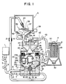
- the surface processing apparatus for carrying out a surface processing method in a preferred embodiment according to the present invention comprises, as principal components, an air compressor 1 for supplying compressed air, a mixing tank 2 in which the compressed air discharged from the air compressor, 1 and submicron particles are mixed, a blasting vessel 3 in which the mixture of the submicron particles and air is blown against a work, and an exhauster 4 for recovering the submicron particles from the blasting vessel 3 by sucking air from the blasting vessel 3.
- An air supply pipe 5 has one end connected to the air compressor 1 and the other end branched into a first air supply pipe 6 and a second air supply pipe 7.
- the first air supply pipe 6 and the second air supply pipe are connected to the mixing tank 2.
- the air supply pipe 5 is provided with a pressure regulating valve 8 for regulating the pressure of the compressed air supplied to the mixing tank 2, and a solenoid valve 9 for controlling the supply of the compressed air to the mixing tank 2.
- the second air supply pipe 7 is provided with a flow regulating valve 10 for regulating the flow of the compressed air through the second air supply pipe 7.
- a hopper 11 containing submicron particles is disposed on top of the mixing tank 2.
- the submicron particles are supplied to the hopper through an opening normally closed by a cover 12.
- the hopper 11 has a funnelform bottom wall provided with a charging opening 11a in its central portion.
- the submicron particles are charged through the charging opening 11a into the mixing tank 2.
- a conical valve element 13 having a stem is fitted in the charging opening 11a.
- the stem of the valve element 13 extends through the central portion of the cover 12, and a stopper 13a is attached to the extremity of the stem of the valve element 13.
- a coil spring 14 is disposed between the stopper 13a and the cover 12 to bias the valve element 13 upward as viewed in Fig. 1 so that the circumference of the conical portion 13b of the valve element 13 is normally in close contact with the lower edge of the bottom wall of the hopper 11 to keep the charging opening 11a closed.
- the valve element 13 is depressed against the resilience of the coil spring 14 to separate the conical portion 13b from the lower edge of the hopper 11 to open the charging opening 11a to let the submicron particles contained in the hopper 11 fall into the mixing tank 2.
- the mixing tank 2 is a cylindrical vessel containing the submicron particles 15.
- the mixing tank 2 has a funnelform bottom wall provided at its lower end with a cermet filter disk 16, namely, a porous disk formed by sintering metal powder and having numerous small pores.
- the first air supply pipe 6 connected to the air compressor 1 is connected to the mixing tank 2 on the side of the backside of the filter disk 16 to supply the compressed air through the first air supply pipe 6 and the filter disk 16 into the mixing tank 2.
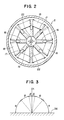
- a plurality of vibrators 17 are arranged on a circle on the funnelform bottom wall of the mixing tank 2 with their free ends facing the upper side of the filter disk 16 as shown in Fig. 2.
- Each vibrator 17 is, for example, a bimorph device having a pair of piezoelectric elements and electrodes.
- the free ends of the vibrators 17 vibrates vertically to disperse the submicron particles 15 mechanically so that the submicron particles 15 and the compressed air supplied through the filter disk 16 into the mixing tank 2 are mixed.
- the frequency of the ac voltage applied to the vibrators 17 may be a high frequency in the range of 200 to 400 Hz. Desirably, the frequency of the ac voltage is approximately equal to the resonance frequency of the bimorph devices. Application of ac voltages of opposite phases to the adjacent vibrators 17 further enhances the effects of the vibrators 17.
- each vibrator 17 is covered with a rubber sheet 18 to prevent the submicron particles 15 from clogging the space under the vibrator 17 so that the vibration of the vibrator 17 is not obstructed.
- a feed pipe 19 having one end opening into the mixing tank 2 is extended through the central portion of the filter disk 16 to send out the submicron particles stirred and dispensed by the compressed air from the mixing tank 2.
- the extremity 7a of the second air supply pipe 7 is inserted in the feed pipe 19 to suck the submicron particles 15 into the feed pipe 19 by the agency of a negative pressure produced by blowing the compressed air through the second air supply pipe 7, to mix the submicron particles 15 in the compressed air and to transport the submicron particles 15 by the compressed air.
- the feed pipe 19 is extended into the blasting vessel 3 and is provided at its extremity with a nozzle 20.
- a vibrator 21 provided on the feed pipe 19 prevents the submicron particles 15 from clogging the feed pipe 19.
- the feed pipe 19 is a flexible tube, such as an urethane tube, a nylon tube or a vinyl tube.
- the feed pipe 19 is extended in a gentle curve without forming sharp bends.
- the pipe is formed so that steps are not formed in junctions so that air may not stagnated in the junctions and the submicron particles may not accumulate to clog the pipe.
- Air jets 22 are formed in the bottom wall of the mixing tank 2 around the feed pipe 19. Part of the compressed air supplied through the first air supply pipe 6 is jetted through the air jets 22 to produce turbulent air currents around the open end 19a of the feed pipe 19 to stir the submicron particles 15 violently.
- a stirring mechanism 24 is attached to the bottom surface of the valve element 13.
- the stirring mechanism 24 comprises a rotary shaft 23 journaled on the valve element 13, an arm 24a projecting from the rotary shaft 23, a frame 24b formed of a metal wire or the like, and a brush 24c attached to the lower end of the frame 24b.
- the rotary shaft 23 is driven for rotation to crush agglomerates of the submicron particles 15 in the mixing tank 2.
- a particle collector 25 is disposed over the feed pipe 19 within the mixing tank 2.
- a particle collecting recess 25a of a trapezoidal cross section is formed in the bottom surface of the particle collector 25 opposite to the open end 19a of the feed pipe 19.
- the upper half portion of the particle collector 25 is formed in a filter 25b of a porous material.
- the filter 25b is connected to the exhauster 4 by a pipe 26.
- the pipe 26 is provided with a solenoid valve 27 and a flow control valve 28 to control the flow and flow rate of exhaust air through the pipe 26.
- the exhauster 4 has a filter 29 and a suction fan 30.
- the suction fan 30 sucks air through the pipe 26 and the filter 29 from the mixing tank 2 and discharges the air through an air outlet 31 after purifying the air by the filter 29.
- the submicron particles arrested by the filter 29 are collected in a pit 32 formed under the filter 29.
- Dehumidifying means 33 such as silica gel
- heating means 34 such as a heater
- the heating elements of a heater 35 is wound round the mixing tank 2 to keep the submicron particles 15 dry within the mixing tank 2 so that the submicron particles 15 may not agglomerate.
- the nozzle 20 attached to the extremity of the feed pipe 19 connected to the mixing tank 2 is held within the blasting vessel 3.
- a turntable 37 for supporting a work 36 is disposed opposite to the nozzle 20.
- the turntable 37 is meshed to prevent the unintended processing of portions, such as side surfaces, of the work 36 by the submicron particles rebounded by the turntable 37.
- the turntable is driven for rotation by a motor 38.
- the turntable 37 is surrounded by the side wall of a suction funnel 39 to prevent the scatter of the submicron particles 15 in the blasting vessel 3.
- the scatter of the submicron particles 15 in the blasting vessel 3 allows the submicron particles 15 to escape outside the blasting vessel 3 when the door of the blasting vessel 3 is opened and reduces particle recovering efficiency.
- the blasting vessel 3 also has a funnelform bottom wall.
- a return pipe 40 is connected to the bottom wall of the blasting vessel 3.
- the return pipe 40 is connected together with a return pipe 41 connected to the suction funnel 39 to the cover 12 of the hopper 11.
- Vibrating means 42 are provided on the bottom wall of the blasting vessel 3 to discharge the submicron particles 15 deposited over the inner surface of the bottom wall rapidly from the blasting vessel 3.
- an exhaust pipe 43 connected together with the pipe 26 to the exhauster 4.
- An annular partition wall 44 extends downward from the inner surface of the cover 12. The partition wall 44 separates, the submicron particles delivered through the return pipes 40 and 41 from air on the principle of a cyclone separator and classifies the submicron particles roughly, so that the submicron particles fall in the hopper 11.
- the air separated from the submicron particles flows through the exhaust pipe 43 into the exhauster 4 and is discharged from the exhauster 4.
- a solenoid valve 45 is provided on the exhaust pipe 43 to control the flow of air.
- the air compressor 1 discharges compressed air into the first air supply pipe 6 and the second air supply pipe 7.
- the compressed air discharged into the first supply pipe 6 flows through the filter disk 16 and the air jets 22 into the mixing tank 2 to stir the submicron particles 15 and, consequently, some of the submicron particles are collected around the open end 19a of the feed pipe 19 by the agency of the particle collecting recess 25a of the particle collector 25.
- the mechanical dispersion of the submicron particles by the vibrating means 17 maintains the stirring effect of the compressed air effectively.
- the solenoid valve 27 provided on the pipe 26 connected to the particle collector 25, and the solenoid valve 45 provided on the exhaust pipe 43 connected to the cover 12 of the hopper 11 are opened alternately at a fixed period.
- the pressure variation in the mixing tank 2 caused by the alternate opening of the solenoid valves 27 and 45 further enhances the stirring effect of the compressed air.
- the flow rate of air flowing out from the mixing chamber 2 is reduced to a fixed value by operating the flow control valve 28, the range of pressure variation is narrowed, so that the submicron particles 15 is brown at a substantially fixed rate regardless of the alternate opening of the solenoid valves 27 and 45.
- the compressed air discharged into the second air supply pipe 7 flows directly into the feed pipe 19 to produce a negative pressure in the feed pipe 19 and, consequently, the submicron particles 15 collected around the open end 19a of the feed pipe 19 are sucked into the feed pipe 19 and are mixed in the compressed air within the feed pipe 19.
- the mixture of the compressed air and the submicron particles flows through the feed pipe 19 and is brown through the nozzle 20 against the surface of the work 36.
- the submicron particles brown into the blasting vessel 3 are returned through the return pipes 40 and 41 to the hopper 11 for recirculation.
- the surfaces of works were processed by blowing the submicron particles against the surfaces at different angles of incidence of the submicron particles brown through the nozzle 20 against the surfaces of the works and the conditions of the thus processed surfaces were examined.
- Fig. 4 is a graph showing the variation of deposition rate with the incident angle. As is obvious from Fig. 4, the deposition rate decreases as the incident angle is increased and, eventually, the deposition rate reaches zero.
- the deposition of a thin film of the submicron particles is a phenomenon peculiar to submicron particles of a small average particle size.
- only submicron particles of an average particle size not greater than 3 ⁇ m can be deposited in a thin film.
- the dependence of the film forming ability of submicron particles on the average particle size is effected slightly by the melting point of the submicron particles.
- Submicron particles having a higher melting point must have a smaller average particle size or the submicron particles are unable to be deposited.in a thin film.
- the energy of submicron particles of an excessively small average particle size is insufficient for film deposition and, in the worst case, such submicron particles cannot be deposited.
- the lower limit of the average particle size is about 0.01 ⁇ m.
- Fig. 6 is a graph showing the relation between the velocity of submicron particles and deposition rate. As is obvious from Fig. 6, submicron particles cannot be deposited unless the velocity thereof is higher than a certain value (50 m/sec) and the lower limit of velocity is higher for submicron particles having a higher melting point.
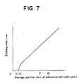
- etching rate increases with the average particle size of submicron particles.
- the average particle size of submicron particles must not exceed 3 ⁇ m.
- the nozzle 20 is able to blow the mixture of compressed air and submicron particles satisfactorily when the width W and length l1 of the outlet of the nozzle 20 meet a relation represented by a straight line shown in Fig. 8(B).
- a portion of a depth in the range of 2 to 10 mm from the extremity of the nozzle 20 of the inner circumference of the nozzle 20 has flat, straight surfaces substantially perpendicular to the surface of a work.
- a plurality of nozzles may be used instead of moving the single nozzle 20 along a straight line.
- the surface processing method was applied to practical film deposition and etching on the basis of the foregoing results of examination. Concrete examples of film deposition and etching processes will be described hereinafter.
- Alumina submicron particles having an average particle size of 1.0 ⁇ m were prepared by crushing a sintered alumina block having a Vickers hardness of 1800 kg/cm2.
- the alumina submicron particles were blown at a velocity of 300 m/sec and at an incident angle of 0° for thirty seconds against the surface of a ferrite substrate having a Vickers hardness of 650 kg/cm2 by the aforesaid surface processing apparatus provided with a nozzle having an outlet slit.
- the particle concentration of the mixture of the compressed air and the alumina submicron particles blown against the surface of the ferrite substrate was about 0.1 g/cm3.
- An alumina thin film of about 2.2 ⁇ m in thickness was deposited.
- Fig. 9 is a photograph of the alumina submicron particles taken by using an electron microscope and Fig. 10 is a photograph of the section of the deposited thin film taken by using an electron microscope.
- the thin film is formed in a very dense construction in such a short time of thirty seconds, which proves the expected effect of the surface processing method.
- Alumina submicron particles of an average particle size of 0.6 ⁇ m were blown against the surface of a ferrite substrate under the same surface processing conditions as those employed for Example 1. A dense alumina thin film was formed.
- a dense alumina thin film was formed also by using alumina submicron particles of an average particle size of 0.2 ⁇ m.
- Alumina submicron particles of an average particle size of 5 ⁇ m were blown against the surface of a ferrite substrate under the same surface processing conditions as employed in Example 1. The alumina submicron particles were not deposited at all and the surface of the ferrite substrate was etched.
- Alumina submicron particles of an average particle size of 0.6 ⁇ m were blown against the surface of a ferrite substrate for etching.
- the width of lines forming a pattern to be formed by etching was 50 ⁇ m.
- a Photosensitive urethane rubber film of 5 ⁇ m in thickness was used as an etching resist.
- the ferrite substrate was rotated at 30 rpm.
- the alumina submicron particles were blown for sixty seconds.
- the surface of the ferrite substrate was etched by a depth of 2 ⁇ m, the inclination of the side surfaces of the lines of the pattern was about 60°, and the etched portions were mirror-finished in a surface roughness R max of 0.06 ⁇ m.
- Alumina submicron particles of an average particle size of 1.0 ⁇ m were blown for ten seconds against the circumference of a cylindrical metal mold formed of a hard stainless steel while the metal mold was rotated at a high rotating speed.
- the circumference of the metal mold was etched in a surface roughness R max of 0.05 ⁇ m.
- the circumference of a metal mold was etched under the same surface processing conditions as those employed in Example 4, except that alumina submicron particles of an average particle size of 6 ⁇ m were used.
- the circumference of the metal mold was etched in a surface roughness R max of 0.07 ⁇ m.
- the present invention using submicron particles of an average particle size not greater than 3 ⁇ m exceeds the prior art in ability of film deposition or etching.
- the present invention is capable of depositing a film at a very high deposition rate and is subject to less restrictions on surface conditions.
- the present invention is capable of accurately etching the surface of a work in a minute pattern at a high etching rate and of finishing an etched surface substantially in a mirror-finished surface.
Landscapes
- Engineering & Computer Science (AREA)
- Chemical & Material Sciences (AREA)
- Mechanical Engineering (AREA)
- Organic Chemistry (AREA)
- Chemical Kinetics & Catalysis (AREA)
- Materials Engineering (AREA)
- Geochemistry & Mineralogy (AREA)
- General Chemical & Material Sciences (AREA)
- Life Sciences & Earth Sciences (AREA)
- Metallurgy (AREA)
- Physics & Mathematics (AREA)
- Plasma & Fusion (AREA)
- Drying Of Semiconductors (AREA)
- Other Surface Treatments For Metallic Materials (AREA)
- Grinding And Polishing Of Tertiary Curved Surfaces And Surfaces With Complex Shapes (AREA)
Applications Claiming Priority (2)
| Application Number | Priority Date | Filing Date | Title |
|---|---|---|---|
| JP26860/90 | 1990-02-06 | ||
| JP2026860A JP2890599B2 (ja) | 1990-02-06 | 1990-02-06 | 加工方法 |
Publications (3)
| Publication Number | Publication Date |
|---|---|
| EP0441300A2 true EP0441300A2 (de) | 1991-08-14 |
| EP0441300A3 EP0441300A3 (en) | 1993-05-12 |
| EP0441300B1 EP0441300B1 (de) | 1996-12-04 |
Family
ID=12205040
Family Applications (1)
| Application Number | Title | Priority Date | Filing Date |
|---|---|---|---|
| EP91101472A Expired - Lifetime EP0441300B1 (de) | 1990-02-06 | 1991-02-04 | Oberflächenbearbeitung durch Strahlen mit submikronischen Teilchen |
Country Status (5)
| Country | Link |
|---|---|
| US (2) | US5928719A (de) |
| EP (1) | EP0441300B1 (de) |
| JP (1) | JP2890599B2 (de) |
| KR (1) | KR100229557B1 (de) |
| DE (1) | DE69123370T2 (de) |
Cited By (11)
| Publication number | Priority date | Publication date | Assignee | Title |
|---|---|---|---|---|
| EP0618041A1 (de) * | 1993-03-22 | 1994-10-05 | Eikichi Yamaharu | Verfahren und Vorrichtung zur Vorbehandlung eines Herstellungsrahmens für elektronische Komponenten |
| WO1996003216A1 (de) * | 1994-07-25 | 1996-02-08 | Siemens Aktiengesellschaft | Verfahren und vorrichtung zur erzeugung und dosierung eines pulveraerosols |
| WO1999066096A1 (de) * | 1998-06-15 | 1999-12-23 | Siemens Aktiengesellschaft | Verfahren und vorrichtung zum erzeugen eines pulveraerosols sowie deren verwendung |
| US6331689B1 (en) | 1999-06-15 | 2001-12-18 | Siemens Aktiengesellschaft | Method and device for producing a powder aerosol and use thereof |
| EP1583163A2 (de) | 2004-03-30 | 2005-10-05 | Brother Kogyo Kabushiki Kaisha | Verfahren zur Herstellung eines Films oder piezoelektrischen Films |
| EP1401615A4 (de) * | 2001-05-25 | 2006-06-07 | Engineered Abrasives Inc | Vorrichtung zum strahlen keramischer materialien und verfahren zur verhinderung von getriebe-lochfrass |
| WO2007006674A1 (de) * | 2005-07-07 | 2007-01-18 | Siemens Aktiengesellschaft | Verfahren zum herstellen einer nanopartikel aufweisenden schicht auf einem substrat |
| WO2008006429A1 (de) * | 2006-07-12 | 2008-01-17 | Eisenmann Lacktechnik Gmbh & Co. Kg | Vorrichtung zum fördern pulverförmiger fluidisierter medien. |
| EP2774688A3 (de) * | 2013-03-07 | 2017-04-19 | Tokyo Electron Limited | Trichter und thermische Sprühvorrichtung |
| WO2019161817A1 (de) * | 2018-02-26 | 2019-08-29 | MTU Aero Engines AG | Beschichtungsvorrichtung für objekte, insbesondere bauteile von strömungsmaschinen |
| CN111996523A (zh) * | 2020-07-15 | 2020-11-27 | 国营芜湖机械厂 | 一种飞机操纵手柄薄壁壳体防变形修复方法 |
Families Citing this family (36)
| Publication number | Priority date | Publication date | Assignee | Title |
|---|---|---|---|---|
| US7622294B2 (en) * | 1997-03-14 | 2009-11-24 | Trustees Of Tufts College | Methods for detecting target analytes and enzymatic reactions |
| US6015586A (en) * | 1998-02-19 | 2000-01-18 | Acheson Industries, Inc. | Cold dry plating process for forming a polycrystalline structure film of zinc-iron by mechanical projection of a composite material |
| US6531187B2 (en) * | 1999-04-23 | 2003-03-11 | Agency Of Industrial Science And Technology | Method of forming a shaped body of brittle ultra fine particles with mechanical impact force and without heating |
| US6827634B2 (en) * | 2000-05-22 | 2004-12-07 | Agency Of Industrial Science And Technology | Ultra fine particle film forming method and apparatus |
| JP2002235181A (ja) * | 1999-10-12 | 2002-08-23 | National Institute Of Advanced Industrial & Technology | 複合構造物及びその製造方法並びに作製装置 |
| KR100724070B1 (ko) * | 1999-10-12 | 2007-06-04 | 도토기키 가부시키가이샤 | 복합 구조물 및 그의 제조방법과 제조장치 |
| AU2001296005A1 (en) * | 2000-10-23 | 2002-05-15 | National Institute Of Advanced Industrial Science And Technology | Composite structure and method for manufacture thereof |
| US6444259B1 (en) * | 2001-01-30 | 2002-09-03 | Siemens Westinghouse Power Corporation | Thermal barrier coating applied with cold spray technique |
| JP4873798B2 (ja) * | 2001-07-19 | 2012-02-08 | 株式会社不二製作所 | 直圧式ブラスト加工装置における微粉研磨材圧送方法、微粉研磨材圧送手段、及び前記微粉研磨材圧送手段を備えた微粉研磨材供給装置 |
| US20030203337A1 (en) * | 2002-04-25 | 2003-10-30 | Roulston John S. | Unexpanded perlite ore polishing composition and methods |
| US7303600B2 (en) | 2002-04-25 | 2007-12-04 | Advanced Minerals Corporation | Unexpanded perlite ore polishing composition and methods |
| JP4769979B2 (ja) * | 2004-03-30 | 2011-09-07 | ブラザー工業株式会社 | 圧電膜の製造方法 |
| KR20060022597A (ko) * | 2004-09-07 | 2006-03-10 | 엘지전자 주식회사 | 플라즈마 디스플레이 패널의 제조방법 |
| JP2006118669A (ja) * | 2004-10-25 | 2006-05-11 | Sanoh Industrial Co Ltd | 樹脂チューブ |
| GB0609829D0 (en) * | 2006-05-18 | 2006-06-28 | Vapormatt Ltd | A sump for a wet blast machine |
| FR2904252B1 (fr) * | 2006-07-27 | 2009-04-24 | Lifco Ind Sarl | Procede physique de depolissage et installation |
| JP5246632B2 (ja) * | 2007-03-05 | 2013-07-24 | 富士通株式会社 | 成膜方法および成膜装置 |
| US8114473B2 (en) * | 2007-04-27 | 2012-02-14 | Toto Ltd. | Composite structure and production method thereof |
| JP5584884B2 (ja) * | 2007-10-01 | 2014-09-10 | シャープ株式会社 | ガラス基板の欠陥修正方法、ガラス基板の製造方法 |
| FI123691B (fi) * | 2007-12-10 | 2013-09-30 | Beneq Oy | Menetelmä erittäin hydrofobisen pinnan tuottamiseksi |
| FI20080264A7 (fi) * | 2008-04-03 | 2009-10-04 | Beneq Oy | Pinnoitusmenetelmä ja -laite |
| CN102476131A (zh) * | 2010-11-26 | 2012-05-30 | 宝山钢铁股份有限公司 | 一种防止高硅带钢断带的冷轧方法 |
| US8771040B1 (en) * | 2011-08-10 | 2014-07-08 | Gus Lyras | Mobile abrasive blasting material separation device and method |
| JP5782338B2 (ja) * | 2011-09-01 | 2015-09-24 | 株式会社不二製作所 | 板材の端部処理方法及びブラスト加工装置 |
| US9022835B1 (en) * | 2013-02-11 | 2015-05-05 | Lyras Gus | Mobile abrasive blasting material separation device and method |
| JP6033145B2 (ja) * | 2013-03-26 | 2016-11-30 | 東芝ホクト電子株式会社 | サーマルプリントヘッドおよびその製造方法 |
| JP2016067991A (ja) * | 2014-09-29 | 2016-05-09 | 株式会社リコー | 洗浄媒体吸引ユニット及び乾式洗浄装置 |
| GB201517128D0 (en) * | 2015-09-28 | 2015-11-11 | Enbio Ltd | Abrasive blast modification of surfaces |
| JP6511009B2 (ja) * | 2016-05-11 | 2019-05-08 | 株式会社スギノマシン | ノズル装置 |
| RU2637538C1 (ru) * | 2016-07-06 | 2017-12-05 | Автономная некоммерческая организация высшего образования "Белгородский университет кооперации, экономики и права" | Способ декорирования стеклоизделий |
| DE102018127450A1 (de) * | 2018-11-04 | 2020-05-07 | systeco GmbH | Oberflächenreinigungs- und Graviermaschine mittels Vakuumstrahlverfahren |
| DE102019219919A1 (de) * | 2019-12-17 | 2021-06-17 | Ab Dry Solutions Ltd | Vorrichtung zur Entnahme und Dosierung von Strahlgut |
| WO2021138545A1 (en) | 2019-12-31 | 2021-07-08 | Cold Jet, Llc | Method and apparatus for enhanced blast stream |
| CN111438640B (zh) * | 2020-05-12 | 2020-12-01 | 杭州拉段机械科技有限公司 | 一种机械零件表面喷砂装置 |
| RU2760667C1 (ru) * | 2021-03-30 | 2021-11-29 | Автономная некоммерческая организация высшего образования «Белгородский университет кооперации, экономики и права» | Способ нанесения декоративного покрытия на закаленные стекла |
| CN116652837B (zh) * | 2023-07-31 | 2023-10-03 | 烟台大学 | 一种金刚石涂层抛光设备及方法 |
Family Cites Families (10)
| Publication number | Priority date | Publication date | Assignee | Title |
|---|---|---|---|---|
| DE2062905A1 (en) * | 1970-12-21 | 1972-06-29 | Siemens Ag | Electric field dispersion powder dispensing method - employs alternating dispersing field through which a conveyor gas is passed |
| US4051275A (en) * | 1974-06-21 | 1977-09-27 | Forestek Clarence W | Embedding and compacting particles in porous surfaces |
| US4020535A (en) * | 1975-08-01 | 1977-05-03 | Metropolitan Circuits, Inc. | Method of making an electro-discharge electrode |
| US4201799A (en) * | 1976-12-27 | 1980-05-06 | Stephens Charles E | Refinish painting apparatus |
| US4370538A (en) * | 1980-05-23 | 1983-01-25 | Browning Engineering Corporation | Method and apparatus for ultra high velocity dual stream metal flame spraying |
| US4397671A (en) * | 1981-11-30 | 1983-08-09 | Ford Motor Company | Method of placing a metal oxide film on a surface of a heated glass substrate |
| FR2575679B1 (fr) * | 1985-01-07 | 1988-05-27 | Saint Gobain Vitrage | Perfectionnement au procede de revetement d'un substrat tel un ruban de verre, par un produit pulverulent, et dispositif pour la mise en oeuvre de ce procede |
| JPS6234778A (ja) * | 1985-08-06 | 1987-02-14 | Niigata Eng Co Ltd | サンドブラストによる物体の加工方法 |
| DE3844648C2 (de) * | 1987-06-23 | 1992-02-20 | Taiyo Sanso Co. Ltd., Osaka, Jp | |
| KR930001712B1 (ko) * | 1988-11-18 | 1993-03-12 | 가부시기 가이샤 다구마 | 와니스 함침(含浸)방법 및 장치 |
-
1990
- 1990-02-06 JP JP2026860A patent/JP2890599B2/ja not_active Expired - Fee Related
-
1991
- 1991-02-04 KR KR1019910001855A patent/KR100229557B1/ko not_active Expired - Fee Related
- 1991-02-04 DE DE69123370T patent/DE69123370T2/de not_active Expired - Fee Related
- 1991-02-04 EP EP91101472A patent/EP0441300B1/de not_active Expired - Lifetime
-
1992
- 1992-10-15 US US07/962,035 patent/US5928719A/en not_active Expired - Fee Related
-
1999
- 1999-03-25 US US09/275,959 patent/US20010007808A1/en not_active Abandoned
Cited By (17)
| Publication number | Priority date | Publication date | Assignee | Title |
|---|---|---|---|---|
| EP0618041A1 (de) * | 1993-03-22 | 1994-10-05 | Eikichi Yamaharu | Verfahren und Vorrichtung zur Vorbehandlung eines Herstellungsrahmens für elektronische Komponenten |
| US5533922A (en) * | 1993-03-22 | 1996-07-09 | Eikichi Yamaharu | Method and apparatus for pretreating electronic component manufacturing frame |
| CN1034895C (zh) * | 1993-03-22 | 1997-05-14 | 山春荣吉 | 用于电子元件制造框架的预处理方法和设备 |
| WO1996003216A1 (de) * | 1994-07-25 | 1996-02-08 | Siemens Aktiengesellschaft | Verfahren und vorrichtung zur erzeugung und dosierung eines pulveraerosols |
| WO1999066096A1 (de) * | 1998-06-15 | 1999-12-23 | Siemens Aktiengesellschaft | Verfahren und vorrichtung zum erzeugen eines pulveraerosols sowie deren verwendung |
| US6331689B1 (en) | 1999-06-15 | 2001-12-18 | Siemens Aktiengesellschaft | Method and device for producing a powder aerosol and use thereof |
| EP1401615A4 (de) * | 2001-05-25 | 2006-06-07 | Engineered Abrasives Inc | Vorrichtung zum strahlen keramischer materialien und verfahren zur verhinderung von getriebe-lochfrass |
| EP1583163A3 (de) * | 2004-03-30 | 2006-04-12 | Brother Kogyo Kabushiki Kaisha | Verfahren zur Herstellung eines Films oder piezoelektrischen Films |
| EP1583163A2 (de) | 2004-03-30 | 2005-10-05 | Brother Kogyo Kabushiki Kaisha | Verfahren zur Herstellung eines Films oder piezoelektrischen Films |
| US7955647B2 (en) | 2004-03-30 | 2011-06-07 | Brother Kogyo Kabushiki Kaisha | Method for manufacturing film or piezoelectric film |
| WO2007006674A1 (de) * | 2005-07-07 | 2007-01-18 | Siemens Aktiengesellschaft | Verfahren zum herstellen einer nanopartikel aufweisenden schicht auf einem substrat |
| US7906171B2 (en) | 2005-07-07 | 2011-03-15 | Siemens Aktiegesellschaft | Method for production of a layer having nanoparticles, on a substrate |
| WO2008006429A1 (de) * | 2006-07-12 | 2008-01-17 | Eisenmann Lacktechnik Gmbh & Co. Kg | Vorrichtung zum fördern pulverförmiger fluidisierter medien. |
| DE102006032184B4 (de) * | 2006-07-12 | 2010-06-17 | Eisenmann Anlagenbau Gmbh & Co. Kg | Vorrichtung zum Fördern pulverförmiger fluidisierter Medien |
| EP2774688A3 (de) * | 2013-03-07 | 2017-04-19 | Tokyo Electron Limited | Trichter und thermische Sprühvorrichtung |
| WO2019161817A1 (de) * | 2018-02-26 | 2019-08-29 | MTU Aero Engines AG | Beschichtungsvorrichtung für objekte, insbesondere bauteile von strömungsmaschinen |
| CN111996523A (zh) * | 2020-07-15 | 2020-11-27 | 国营芜湖机械厂 | 一种飞机操纵手柄薄壁壳体防变形修复方法 |
Also Published As
| Publication number | Publication date |
|---|---|
| DE69123370D1 (de) | 1997-01-16 |
| DE69123370T2 (de) | 1997-06-19 |
| EP0441300B1 (de) | 1996-12-04 |
| KR100229557B1 (ko) | 1999-11-15 |
| EP0441300A3 (en) | 1993-05-12 |
| JPH03231096A (ja) | 1991-10-15 |
| US20010007808A1 (en) | 2001-07-12 |
| JP2890599B2 (ja) | 1999-05-17 |
| KR910016045A (ko) | 1991-09-30 |
| US5928719A (en) | 1999-07-27 |
Similar Documents
| Publication | Publication Date | Title |
|---|---|---|
| US5928719A (en) | Surface processing method by blowing submicron particles | |
| US6074135A (en) | Coating or ablation applicator with debris recovery attachment | |
| JP2000517243A (ja) | 表面上に制御された粒子蒸着を行う方法及び装置 | |
| JP2011042856A (ja) | 成膜装置及び成膜方法 | |
| JP2004265992A (ja) | 複合構造物作製装置 | |
| JP2003166076A (ja) | 複合構造物作製方法及び複合構造物作製装置 | |
| JPH05301066A (ja) | パウダービームコーティング方法 | |
| US5150511A (en) | Method for manufacturing a magnetic transducer head | |
| JP4063156B2 (ja) | 複合構造物作製装置および作製方法 | |
| JP3196314B2 (ja) | 粉体供給装置 | |
| JP4115145B2 (ja) | エアロゾル発生装置及びそれを備えた複合構造物作製装置 | |
| US5173121A (en) | Apparatus for the deposition and film formation of silicon on substrates | |
| JPH02131871A (ja) | サンドブラスト装置 | |
| JP5066682B2 (ja) | 脆性材料微粒子成膜体の低温成形法 | |
| JP3196312B2 (ja) | 粉体供給方法及び装置 | |
| JP4741447B2 (ja) | 成膜方法及び成膜装置 | |
| JP2580745B2 (ja) | サンドブラスト装置 | |
| JP3702775B2 (ja) | 砥粒の分級方法およびその装置 | |
| JP3104721B2 (ja) | 微粒子噴射加工装置 | |
| KR102220056B1 (ko) | 파우더 공급 장치 및 이를 구비하는 설비 코팅 시스템 | |
| JP4075719B2 (ja) | エアロゾル発生装置及び複合構造物作製装置 | |
| JPH05285838A (ja) | 加工装置における粉体噴射量制御システム | |
| JPH06114737A (ja) | 粉体供給装置 | |
| JP2007254826A (ja) | 被膜形成装置および被膜形成方法 | |
| JP2024140082A (ja) | 成膜装置 |
Legal Events
| Date | Code | Title | Description |
|---|---|---|---|
| PUAI | Public reference made under article 153(3) epc to a published international application that has entered the european phase |
Free format text: ORIGINAL CODE: 0009012 |
|
| AK | Designated contracting states |
Kind code of ref document: A2 Designated state(s): DE FR GB |
|
| PUAL | Search report despatched |
Free format text: ORIGINAL CODE: 0009013 |
|
| AK | Designated contracting states |
Kind code of ref document: A3 Designated state(s): DE FR GB |
|
| 17P | Request for examination filed |
Effective date: 19931012 |
|
| 17Q | First examination report despatched |
Effective date: 19941212 |
|
| GRAG | Despatch of communication of intention to grant |
Free format text: ORIGINAL CODE: EPIDOS AGRA |
|
| GRAH | Despatch of communication of intention to grant a patent |
Free format text: ORIGINAL CODE: EPIDOS IGRA |
|
| GRAH | Despatch of communication of intention to grant a patent |
Free format text: ORIGINAL CODE: EPIDOS IGRA |
|
| GRAA | (expected) grant |
Free format text: ORIGINAL CODE: 0009210 |
|
| AK | Designated contracting states |
Kind code of ref document: B1 Designated state(s): DE FR GB |
|
| REF | Corresponds to: |
Ref document number: 69123370 Country of ref document: DE Date of ref document: 19970116 |
|
| ET | Fr: translation filed | ||
| PLBE | No opposition filed within time limit |
Free format text: ORIGINAL CODE: 0009261 |
|
| STAA | Information on the status of an ep patent application or granted ep patent |
Free format text: STATUS: NO OPPOSITION FILED WITHIN TIME LIMIT |
|
| 26N | No opposition filed | ||
| REG | Reference to a national code |
Ref country code: GB Ref legal event code: IF02 |
|
| PGFP | Annual fee paid to national office [announced via postgrant information from national office to epo] |
Ref country code: GB Payment date: 20020206 Year of fee payment: 12 |
|
| PGFP | Annual fee paid to national office [announced via postgrant information from national office to epo] |
Ref country code: FR Payment date: 20020212 Year of fee payment: 12 |
|
| PGFP | Annual fee paid to national office [announced via postgrant information from national office to epo] |
Ref country code: DE Payment date: 20020227 Year of fee payment: 12 |
|
| PG25 | Lapsed in a contracting state [announced via postgrant information from national office to epo] |
Ref country code: GB Free format text: LAPSE BECAUSE OF NON-PAYMENT OF DUE FEES Effective date: 20030204 |
|
| PG25 | Lapsed in a contracting state [announced via postgrant information from national office to epo] |
Ref country code: DE Free format text: LAPSE BECAUSE OF NON-PAYMENT OF DUE FEES Effective date: 20030902 |
|
| GBPC | Gb: european patent ceased through non-payment of renewal fee | ||
| PG25 | Lapsed in a contracting state [announced via postgrant information from national office to epo] |
Ref country code: FR Free format text: LAPSE BECAUSE OF NON-PAYMENT OF DUE FEES Effective date: 20031031 |
|
| REG | Reference to a national code |
Ref country code: FR Ref legal event code: ST |