EP0441310A2 - Système de gestion de chargement de dock - Google Patents
Système de gestion de chargement de dock Download PDFInfo
- Publication number
- EP0441310A2 EP0441310A2 EP91101502A EP91101502A EP0441310A2 EP 0441310 A2 EP0441310 A2 EP 0441310A2 EP 91101502 A EP91101502 A EP 91101502A EP 91101502 A EP91101502 A EP 91101502A EP 0441310 A2 EP0441310 A2 EP 0441310A2
- Authority
- EP
- European Patent Office
- Prior art keywords
- data
- module
- master control
- shift register
- modules
- Prior art date
- Legal status (The legal status is an assumption and is not a legal conclusion. Google has not performed a legal analysis and makes no representation as to the accuracy of the status listed.)
- Withdrawn
Links
- 238000012546 transfer Methods 0.000 claims abstract description 18
- 238000012544 monitoring process Methods 0.000 claims abstract description 17
- 230000008859 change Effects 0.000 claims abstract description 7
- 230000008878 coupling Effects 0.000 claims 6
- 238000010168 coupling process Methods 0.000 claims 6
- 238000005859 coupling reaction Methods 0.000 claims 6
- 230000001360 synchronised effect Effects 0.000 claims 1
- 238000012545 processing Methods 0.000 abstract description 10
- 239000004020 conductor Substances 0.000 description 15
- 239000013256 coordination polymer Substances 0.000 description 5
- 238000010586 diagram Methods 0.000 description 5
- 238000009434 installation Methods 0.000 description 5
- 230000000694 effects Effects 0.000 description 4
- 238000003032 molecular docking Methods 0.000 description 4
- 230000006872 improvement Effects 0.000 description 3
- 238000007726 management method Methods 0.000 description 3
- 230000004044 response Effects 0.000 description 3
- 230000000452 restraining effect Effects 0.000 description 3
- 230000005540 biological transmission Effects 0.000 description 2
- 238000004891 communication Methods 0.000 description 2
- 230000003111 delayed effect Effects 0.000 description 2
- 230000006870 function Effects 0.000 description 2
- 238000002955 isolation Methods 0.000 description 2
- 238000004519 manufacturing process Methods 0.000 description 2
- 238000012986 modification Methods 0.000 description 2
- 230000004048 modification Effects 0.000 description 2
- 230000008054 signal transmission Effects 0.000 description 2
- 230000001960 triggered effect Effects 0.000 description 2
- 230000003750 conditioning effect Effects 0.000 description 1
- 238000011161 development Methods 0.000 description 1
- 230000002452 interceptive effect Effects 0.000 description 1
- 238000000034 method Methods 0.000 description 1
- 230000008569 process Effects 0.000 description 1
- 230000001681 protective effect Effects 0.000 description 1
- 238000012552 review Methods 0.000 description 1
- 230000001052 transient effect Effects 0.000 description 1
Images


Classifications
-
- B—PERFORMING OPERATIONS; TRANSPORTING
- B65—CONVEYING; PACKING; STORING; HANDLING THIN OR FILAMENTARY MATERIAL
- B65G—TRANSPORT OR STORAGE DEVICES, e.g. CONVEYORS FOR LOADING OR TIPPING, SHOP CONVEYOR SYSTEMS OR PNEUMATIC TUBE CONVEYORS
- B65G69/00—Auxiliary measures taken, or devices used, in connection with loading or unloading
- B65G69/003—Restraining movement of a vehicle at a loading station using means not being part of the vehicle
Definitions
- This invention relates to a dock monitoring system and more particularly to improvements relating to transmission and processing of data in a monitoring system such as used for monitoring operations at a truck docking facility to obtain improved safety and traffic control and to facilitate scheduling and planning.
- the invention facilitates installation of equipment, provides increased reliability and minimizes manufacturing and other expenses.
- the Hahn U.S. Patent No. 4,692,755 discloses a system in which signal lights are provided on the inside and outside of a dock facility to give dock personnel and truck drivers clearly visible indications of when it is safe or unsafe to load or unload a truck or to park or remove a truck, and to provide other safety features.
- An improvement of the system of the Hahn Patent is disclosed in the Trickle et al. U. S. Patent No, 4,843,373 issued June 27, 1989.
- the system of the Trickle et al. patent includes a programmable control unit which is versatile and provides various safe and reliable modes of operation, being also operable to perform diagnostic operations.
- a monitoring system is provided for installation at a multi-position docking facility which includes a locking device at each position for restraining a truck against movement during loading/unloading operations.
- the system is relatively inexpensive but permits a controller or dispatcher at a multi-position truck docking facility to easily and instantaneously obtain information as to the current status of the locking device at each truck unloading position and, in addition, to obtain information as to the length of time that each operated lock device has been in its locked condition.
- Information from each loading position on the dock is received from sensing devices located in each position. Each time a change occurs in the status of any one of the positions, the change is recorded so that over time a picture of the comings and goings as a whole is built up. Such information is usable on a day to day basis and is also accumulated over longer periods.
- a data processor is used which is preferably a standard type of personal computer and associated keyboard and monitor available commercially at relatively low cost.
- the data processor is operable by a keyboard and is adapted to receive signals placed in each of the loading/unloading positions of a loading dock facility.
- the sensors coupled to the data processor include lock condition sensing means for developing locked and unlocked signals respectively corresponding to the locked and unlocked condition of a truck in the at each of the positions.
- the data processor is operable to continually process signals from the lock condition sensing means and includes a display screen to enable a plurality of types of data to be displayed.
- the types of data available include the current lock condition data which shows the current status of each of the lock conditioning means and the load time data showing the time of development of each locked signal and the data processor may also be coupled to truck sensing means for developing empty and in-door signals corresponding to the existence or otherwise of a truck in each of the loading/unloading positions.
- This invention was evolved with the general object of improving upon the system of my prior application, particularly with respect to facilitating installation of a system and obtaining improved performance and reliability, while reducing manufacturing and operational expenses.
- a management system which includes a daisy chain arrangement for serial transfer of dock status data from one module to another of a group of monitoring modules and to a central processing unit.
- the arrangement greatly reduces problems in installation and also greatly reduces the number of required isolation interfaces and other components, as well as in the number of wires in interconnecting cables.
- Important features relate to the provision of a master control box which periodically receives dock status data from one or more groups of modules and stores such information for subsequent transfer to the central processing unit or a display unit. In one mode of operation, it determines whether any change of status has occurred and transmits data to a central processing unit.
- Reference numeral 10 generally designates a management system which is constructed in accordance with the principles of this invention, the illustrated system being arranged for monitoring conditions at docks of a multi-position dock facility.
- the system is particularly advantageous in facilities in which there are a large number of docks and, as illustrated, is usable to monitor conditions at up to 128 truck loading/unloading positions or "doors", a door being typically provided at each position. It will be understood that the invention is not limited to monitoring conditions at any particular number of positions or doors.
- a vehicle restraining or locking device is provided at each door, arranged to engage a standard type of bumper which includes a transverse horizontal bar at the rear of a truck or trailer, required by I.C.C. regulations and commonly referred to as a "ICC" bar.
- a vehicle restraint sensor may be provided for sensing whether the restraining device is in a locked or unlocked position and truck sensor may also be provided for sensing whether or not a truck or trailer is positioned at loading/unloading position.
- the truck sensor may be in the form of an overhead photoelectric sensor, for example.
- the conditions of such vehicle restraint and truck sensors are monitored using a monitoring module at each door with all monitoring modules being connected through a master control box 11 to a central processor unit 12.
- the central processor unit 12 may preferably include a standard type of personal computer such as an IBM PC or compatible, connected to a keyboard and monitor and including disc drives for storage of information.
- a permanent record may be obtained as to activities at all doors for review as desired, and a dispatcher may readily and quickly obtain information as to the status of conditions at each door for efficient control of traffic at the facility.
- the modules are divided into four groups of 32 each, a first group for door #'s 1-32, a second group for door #'s 33-64, a third group for door #'s 65-96 and a fourth group for door #'s 97-128.
- Modules for door #'s 1, 2, 31 and 32 of the first are shown in Figure 1 and are designated by reference numerals 13, 14, 15 and 16.
- the modules are connected together and to the master control box 11 in daisy chain fashion.
- the module 13 for door #1 is connected through a cable 17 to the master control box 11 and through a cable 18 to the module 14 for door #2, module 14 being connected through a cable 19 to a module, not shown for door #3.
- Module 15 for door #31 is connected through a cable 20 to a module, not shown, for door #30 and through a cable 21 to module 16 which is for door #32.
- Each of the cables 17-21 has two pairs of conductors which provide two signal transmission channels, one for transmission of data signals and the other for transmission of signals which serve both to supply power to circuits of the modules and to perform control and clock or timing functions.
- the conductors of each pair conduct signals in balanced relation to ground and are surrounded by a protective conductive shield as shown, and/or by an external conduit, connected at opposite ends to ground or shield terminals to minimize interferences of electromagnetic origin. Installation is simple and is readily accomplished.
- shields 23 and 24 of cables 17 and 18 are connected to a shield terminal 25 of module 13.
- Conductors 27 and 28 of cable 17 are connected to a pair of "data out” terminals 29 and 30 of module 13; conductors 31 and 32 of cable 17 and conductors 33 and 34 of cable 18 are connected to a pair of "power/clock” terminals 35 and 36 of module 13; and conductors 37 and 38 of cable 18 are connected to "data in” terminals 39 and 40 of module 13.
- module 13 The only additional required connections for module 13 are connections from terminals 41 and 42 to a vehicle restraint sensor of door #1 and connections from terminals 43 and 44 to a truck sensor for door #1.
- the connections for the other modules are same as for module 13 with the exception of the end module 16 in which there are no connections to "data in” terminals thereof. All modules have connections through cable conductors from "data out” terminals thereof to "data in” terminals of a preceding module or, in the case of the first module 13, to terminals of master control box. All modules have connections through cable conductors to "power/clock" terminals thereof. The modules do not require any connection to any voltage supply source, other than those provided through the cables.
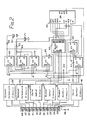
- FIG. 2 is a schematic diagram of circuitry for the module 13 which is the same as for all other modules. As shown, the shield terminal 25 is connected through a resistor 45 to a circuit ground and the "data out" terminals 29 and 30 are connected to a data output circuit 46.
- the "power/clock" terminals 35 and 36 are connected to a power supply circuit 47 and also to a clock input circuit 48.
- a 2 KHz square wave voltage developed by the master control box 11 and applied to the terminals 35 and 36 is converted by the power supply circuit to a +5 volt DC voltage on a line 50 to supply an operating voltage to circuits of the module.
- the 2 KHz voltage is also processed by the clock input circuit 48 to develop clock signals on lines 51 and 52, the signal on line 52 being in delayed relation to the signal on line 51.
- the "data in” terminals 39 and 40 are connected to a data input circuit 54 while the vehicle restraint sensor terminals 41 and 42 and the truck sensor terminals 43 and 44 are connected to sensor interface circuits 55 and 56.
- Each of the circuits 46-48 and 54-56 includes voltage limiting and transient protection means with excess current protection.
- the sensor interface circuits can accept voltages within a very wide range of values.
- a four stage integrated circuit shift register 58 which has a Q3 output connected to an input of the data output circuit 46.
- a CP input is connected to a Q output of a clocking flip-flop 60 which has a D input connected to an inverted Q output thereof and which has a CP input connected to the clock signal line 51.
- Reset inputs of the shift register 58 and the flip-flop 60 are connected to a Q output of a reset flip-flop 61 which has reset and CP inputs connected to the clock signal lines 51 and 52.
- the reset flip-flop is initially reset to reset the clocking flip-flop 60 and the shift-register 58.
- the reset flip-flop is then triggered to a set condition by a delayed clock signal applied through line 52 and the clocking flip-flop is thereafter triggered by clock signals applied through line 51 to apply clock signals to the shift register 58.
- the four stage shift register 58 has additional inputs connected to outputs of four flip-flops in a quad flip-flop integrated circuit 62.
- a P/S input is connected to a Q0 output of a first flip-flop of circuit 62
- J and K inputs are connected together and to a Q1 output of a second flip-flop of circuit 62
- inputs DP0, DP1, DP2 and DP3 are respectively connected to outputs of third and fourth flip-flops of the circuit 62.
- a D0 input to the first flip-flop of circuit 62 is connected to the Q output of the reset flip-flop 61, a D1 input to the second flip-flop is connected to the clock signal line 51 and D2 and D3 inputs of the third and fourth flip-flops are connected to outputs of the sensor interface circuits 56 and 55, respectively.
- the first flip-flop of circuit 62 operates to effect a parallel load of sensor signals stored in the third and fourth flip-flops into stages of the shift register.
- the second flip-flop of circuit 62 is thereafter operative to effect a serial transfer of data signals into the J and K inputs of the shift register 58 to be shifted through the stages of the shift register 58 in response to clock signals applied thereto.
- flip-flop 65 has a CP input connected to the Q3 output of the shift register 58 and is connected to a flip-flop 66 as shown having a Q output connected through a resistor 68 to energize a "data out” LED 67 in response to output signals.
- a flip flop 69 has a CP input connected to the Q1 output of the second flip flop of the circuit 62 and is connected to a flip flop 70 which has a Q output connected through a resistor 72 to energize a "data in” LED 71 in response to input signals.
- Figure 3 is a schematic diagram of circuitry of the master control box 11.
- a pair of terminals 75 and 76 are provided which are connected through the conductors 27 and 28 of the cable 17 to the "data out" terminals 29 and 30 of the module 13.
- Another pair of terminals 77 and 78 are provided which are connected through conductors 31 and 32 of the cable 17 to "power ⁇ clock" terminals 35 and 36 of the module 13.
- a shield terminal 79 is connected to the shield of cable 17 and through a resistor 80 to ground.
- the terminals 75 and 76 are connected to a data signal transfer circuit 82 which has an output connected through an opto isolator circuit 83 to a line 84 which is connected to microprocessor and memory circuits 86.
- the terminals 77 and 78 are connected to outputs of a clock circuit 88 which is arranged to supply 2 Khz signals thereto and which is controlled through an opto isolator circuit 89 and a line 90 from the microprocessor and memory circuits 86.
- the data signal transfer circuit 82 and the clock circuit 88 are also connected to other groups of modules as indicated by the arrows in Figure 3.
- the data signal transfer circuit 82 is connected through opto isolate circuits 92 to input ⁇ output ports of the microprocessor and memory circuits 86 for the purpose of having the capability of transmitting data signals to modules as well as having the capability of passively receiving data signals from the modules.
- the passive mode of operation is used but it will be understood that the same principles of operation may be used for transmitting data to the modules.
- An interface circuit 94 which may preferably generate signals in accordance with the RS 232 standard, has an output coupled through a four conductor cable 95 to the central processing unit 12, one of the conductors being a shield conductor, another being a clear-to-send ⁇ data-set-ready conductor and the other two being RX and TX conductors.
- RX and TX inputs of the interface circuit 94 are connected through lines 97 and 98, opto isolate circuits 100 and RX and TX lines 101 and 102 of the microprocessor and memory circuits.
- data may be transmitted from the master control box 11 to a display or other data receiving unit. Either serial or parallel communications may be used in each case and standards other than the RS 232 standard such as the RS485 and RS422 standards may be used.
- a power supply circuit 106 is provided which supplies voltages for operation of the interface circuit 94 and which also develops supply voltages on lines 107 and 108 which are isolated from one another and which may be +5 volts, for example.
- the voltage on line 107, labelled "C” is applied to the microprocessor and memory circuits, through resistors 109 and 110 to the lines 84 and 90 on the microprocessor side of the opto isolators 83 and 89.
- the voltage on line 108, labelled "S" is applied to the data signal transfer circuit 82, the clock circuit 88, the opto isolate circuits 92, and through resistors 111 and 112 to the portions of the opto isolators 83 and 89 which are required to be isolated from the microprocessor and memory circuits 86.
- the clock circuit 88 is preferably arranged to develop differential signals which are preferably at a voltage of on the order of +24 volts in accordance with RS485 standards and which are 2 Khz pulses used for both applying an operating voltage to each of the modules and also for performing clock and timing functions.
- the clock circuit 88 is so controlled from the microprocessor of the microprocessor and memory circuits 86 as to be periodically inoperative for a 50 millisecond reset period in which no clock pulses are generated and to then generate a train of 256 clock pulses at 0.25 millisecond intervals, being operative back to a reset condition after 256 counts.
- the line 84 is monitored by the microprocessor to receive the train of data transmitted from the modules 13 and the other modules of the group of 32, operating in effect to observe data at every 4th edge to receive a train of 64 data bits.
- Such bits are stored along the 64 bits received from each of the other three groups of 32 modules each.
- a total of 256 bits are available from a total of 128 possible modules. It is noted that the system may accommodate any lesser number of modules, no modifications being necessary. If there are less than 32 modules in any group, there will simply be no reported data for the absent modules.
- the central processing unit 12 can keep asking for information from the master control box 11.
- the central processing unit may receive information whenever there is a change in the data stream of bits received by the master control box 11.
- the central processing unit may receive information whenever there is a change in the data stream of bits received by the master control box 11.
- the memory circuits of the microprocessor and memory circuits 86 the bits from each received series of bits are stored for comparison with the bits received in the next operation and the system may operate to automatically initiate communication to the central processing unit when such a change is detected.
- the system may also incorporate suitable operations using check sums to verify the accuracy of the received information.
Landscapes
- Engineering & Computer Science (AREA)
- Mechanical Engineering (AREA)
- Selective Calling Equipment (AREA)
- Burglar Alarm Systems (AREA)
Applications Claiming Priority (2)
| Application Number | Priority Date | Filing Date | Title |
|---|---|---|---|
| US477599 | 1990-02-09 | ||
| US07/477,599 US5168267A (en) | 1990-02-09 | 1990-02-09 | Loading dock management system employing daisy-chained communications modules |
Publications (2)
| Publication Number | Publication Date |
|---|---|
| EP0441310A2 true EP0441310A2 (fr) | 1991-08-14 |
| EP0441310A3 EP0441310A3 (en) | 1993-01-27 |
Family
ID=23896587
Family Applications (1)
| Application Number | Title | Priority Date | Filing Date |
|---|---|---|---|
| EP19910101502 Withdrawn EP0441310A3 (en) | 1990-02-09 | 1991-02-05 | Loading dock management system |
Country Status (3)
| Country | Link |
|---|---|
| US (1) | US5168267A (fr) |
| EP (1) | EP0441310A3 (fr) |
| CA (1) | CA2035850A1 (fr) |
Cited By (2)
| Publication number | Priority date | Publication date | Assignee | Title |
|---|---|---|---|---|
| EP0696005A3 (fr) * | 1994-08-04 | 1997-11-26 | Fluke Corporation | Système à bord de mesure |
| EP1081071A1 (fr) * | 1999-09-02 | 2001-03-07 | Bruce Stanley Gunton | Systeme de contole pour rampes de chargement |
Families Citing this family (33)
| Publication number | Priority date | Publication date | Assignee | Title |
|---|---|---|---|---|
| US5831540A (en) * | 1995-07-24 | 1998-11-03 | United Dominion Ind., Inc. | Control system for loading docks |
| JP2001134316A (ja) * | 1999-11-09 | 2001-05-18 | Toshiba Corp | 制御システムのモニタ装置 |
| US20010042024A1 (en) * | 2000-02-15 | 2001-11-15 | Rogers Theodore Gordon | System to provide web-based sales involving storage facilities |
| US20050028723A1 (en) | 2002-02-19 | 2005-02-10 | Ancel Thomas A. | Loading dock traffic automation and inventory control system |
| US6812849B1 (en) * | 2000-12-12 | 2004-11-02 | Thomas A. Ancel | Loading dock traffic automation |
| US7119673B2 (en) * | 2004-05-21 | 2006-10-10 | Spx Corporation | Loading dock monitoring system and apparatus |
| US8497761B2 (en) | 2005-01-13 | 2013-07-30 | Rite-Hite Holding Corporation | System and method for remotely controlling docking station components |
| US20080124203A1 (en) * | 2005-07-26 | 2008-05-29 | Advanced Systems, Inc. | Integrated vehicle docking system and related method |
| DE102005038343B4 (de) | 2005-08-13 | 2022-01-05 | Alten Gerätebau Gesellschaft mit beschränkter Haftung | Verladestellenmanagementeinrichtung |
| US8627529B1 (en) * | 2011-12-14 | 2014-01-14 | Systems, Inc. | Centralized air supply loading dock leveling system |
| US9481531B2 (en) * | 2014-02-27 | 2016-11-01 | Rite-Hite Holding Corporation | Monitoring vehicle restraints over a continuous range of positions |
| US10081504B2 (en) | 2014-05-02 | 2018-09-25 | Assa Abloy Entrance Systems Ab | Systems and methods for automatically controlling loading dock equipment |
| US11234581B2 (en) | 2014-05-02 | 2022-02-01 | Endochoice, Inc. | Elevator for directing medical tool |
| US10781062B2 (en) | 2015-11-24 | 2020-09-22 | Systems, LLC | Vehicle restraint system |
| US11225824B2 (en) | 2016-05-03 | 2022-01-18 | Assa Abloy Entrance Systems Ab | Control systems for operation of loading dock equipment, and associated methods of manufacture and use |
| US11305953B2 (en) | 2016-05-03 | 2022-04-19 | Assa Abloy Entrance Systems Ab | Control systems for operation of loading dock equipment, and associated methods of manufacture and use |
| WO2018053416A1 (fr) * | 2016-09-19 | 2018-03-22 | The Chamberlain Group, Inc. | Actionnement de barrière sensible à la position |
| US10906759B2 (en) | 2017-06-28 | 2021-02-02 | Systems, LLC | Loading dock vehicle restraint system |
| US10745220B2 (en) | 2017-06-28 | 2020-08-18 | Systems, LLC | Vehicle Restraint System |
| US10878386B2 (en) | 2018-11-26 | 2020-12-29 | Assa Abloy Entrance Systems Ab | Systems and methods for automated dock station servicing |
| US10494205B1 (en) | 2018-12-06 | 2019-12-03 | Assa Abloy Entrance Systems Ab | Remote loading dock authorization systems and methods |
| USD959389S1 (en) | 2019-01-08 | 2022-08-02 | Assa Abloy Entrance Systems Ab | Portion of a loading dock control panel |
| USD894229S1 (en) | 2019-01-08 | 2020-08-25 | Assa Abloy Entrance Systems Ab | Display screen with graphical user interface |
| USD929617S1 (en) | 2019-01-09 | 2021-08-31 | Assa Abloy Entrance Systems Ab | Light sources arranged in a pattern |
| US11142413B2 (en) | 2019-01-28 | 2021-10-12 | Assa Abloy Entrance Systems Ab | Systems and methods for automated loading and unloading at a dock station |
| US11262747B2 (en) | 2019-06-11 | 2022-03-01 | Assa Abloy Entrance Systems Ab | Vehicle identification and guidance systems and associated methods |
| USD1012747S1 (en) | 2019-10-24 | 2024-01-30 | Assa Abloy Entrance Systems Ab | Signal light for a loading dock with patterns of projected light |
| USD1014306S1 (en) | 2019-10-24 | 2024-02-13 | Assa Abloy Entrance Systems Ab | Signal light for a loading dock |
| US12297062B1 (en) | 2020-09-21 | 2025-05-13 | The Chamberlain Group Llc. | System and method for restraining a vehicle proximate a loading dock |
| MX2022003569A (es) | 2021-03-24 | 2023-02-22 | Blue Giant Equipment Corp | Sistema de energia y control para un ensamble de cubierta de carga. |
| US12570129B2 (en) | 2021-06-02 | 2026-03-10 | Assa Abloy Entrance Systems Ab | Loading dock automated trailer door systems |
| EP4363685B1 (fr) | 2021-07-02 | 2025-12-10 | ASSA ABLOY Entrance Systems AB | Systèmes de remorque motorisés |
| US12400175B2 (en) | 2021-11-30 | 2025-08-26 | Assa Abloy Entrance Systems Ab | Trailer validation systems |
Family Cites Families (20)
| Publication number | Priority date | Publication date | Assignee | Title |
|---|---|---|---|---|
| GB1178991A (en) * | 1966-01-24 | 1970-01-28 | Gen Alarm Corp | Security alarm system |
| US3927404A (en) * | 1973-10-18 | 1975-12-16 | Standard Electric Time Corp | Time division multiple access communication system for status monitoring |
| US3969584A (en) * | 1975-01-17 | 1976-07-13 | Cecil John Miller | System for recording the actuation of remotely located locking devices |
| US4205300A (en) * | 1976-08-30 | 1980-05-27 | Techne Electronics, Ltd. | Vehicle antitheft alarm |
| EP0006403B1 (fr) * | 1977-01-08 | 1981-09-23 | Tele-Alarm, Nachrichtentechnische Geräte GmbH Herstellungs- und Vertriebsgesellschaft & Co.KG | Système de compartiments verrouillables commandé par un processeur central |
| US4146779A (en) * | 1977-02-28 | 1979-03-27 | Osborne-Hoffman, Inc. | Display controller for time recorders and time actuators |
| US4127856A (en) * | 1977-04-11 | 1978-11-28 | Bickel Gary G | Vehicle-dock latching apparatus |
| US4222047A (en) * | 1978-11-06 | 1980-09-09 | Finnegan George E | Lamp failure detection apparatus |
| US4264259A (en) * | 1979-09-06 | 1981-04-28 | Rite-Hite Corporation | Releasable locking device |
| US4831374A (en) * | 1983-03-14 | 1989-05-16 | Barry Masel | Electric lock system |
| US4581605A (en) * | 1984-02-13 | 1986-04-08 | Baker Industries, Inc. | System for displaying time-related occurrence of alarm-type events |
| US4692755A (en) * | 1985-02-22 | 1987-09-08 | Rite-Hite Corporation | Loading dock signal and control system |
| US4700295A (en) * | 1985-04-18 | 1987-10-13 | Barry Katsof | System and method for forecasting bank traffic and scheduling work assignments for bank personnel |
| US4648781A (en) * | 1985-05-29 | 1987-03-10 | Tomar Electronics, Inc. | Automatic control system for a releasable vehicle locking device |
| US4818170A (en) * | 1987-02-24 | 1989-04-04 | Nova Technologies, Inc | Driveway truck restraining apparatus |
| US4858120A (en) * | 1987-03-18 | 1989-08-15 | International Telesystems Corp. | System for regulating arrivals of customers to servers |
| US4830563A (en) * | 1987-06-09 | 1989-05-16 | Vestil Manufacturing Company | Multi-condition responsive vehicle restraining apparatus |
| US4843373A (en) * | 1987-12-10 | 1989-06-27 | Rite-Hite Corporation | Loading dock signal and control system |
| US4912687A (en) * | 1988-10-26 | 1990-03-27 | Eagle River Industries, Inc. | Time of tip-over indicator |
| US5047748A (en) * | 1989-04-21 | 1991-09-10 | Rite-Hite Corporation | Dock monitoring system |
-
1990
- 1990-02-09 US US07/477,599 patent/US5168267A/en not_active Expired - Fee Related
-
1991
- 1991-02-05 EP EP19910101502 patent/EP0441310A3/en not_active Withdrawn
- 1991-02-06 CA CA002035850A patent/CA2035850A1/fr not_active Abandoned
Non-Patent Citations (2)
| Title |
|---|
| IEEE IECON '83 PROCEEDINGS. ANNUAL CONFERENCE ON INDUSTRIAL ELECTRONICS. 7-11 NOVEMBER 1983, SAN FRANCISCO, CA, US pages 49 - 51 D.J. BUCKLEY ET AL 'A Microcomputer-Based Distributed Event Monitoring System' * |
| IEEE TRANSACTIONS ON NUCLEAR SCIENCE vol. NS-34, no. 4, August 1987, NEW YORK US pages 790 - 795 A.W. BOOTH ET AL 'The CDF Event-Builder' * |
Cited By (3)
| Publication number | Priority date | Publication date | Assignee | Title |
|---|---|---|---|---|
| EP0696005A3 (fr) * | 1994-08-04 | 1997-11-26 | Fluke Corporation | Système à bord de mesure |
| EP1081071A1 (fr) * | 1999-09-02 | 2001-03-07 | Bruce Stanley Gunton | Systeme de contole pour rampes de chargement |
| US6329931B1 (en) | 1999-09-02 | 2001-12-11 | Bruce Stanley Gunton | Loading bay dock control |
Also Published As
| Publication number | Publication date |
|---|---|
| US5168267A (en) | 1992-12-01 |
| EP0441310A3 (en) | 1993-01-27 |
| CA2035850A1 (fr) | 1991-08-10 |
Similar Documents
| Publication | Publication Date | Title |
|---|---|---|
| US5168267A (en) | Loading dock management system employing daisy-chained communications modules | |
| DE69634441T2 (de) | Optische zwischenstelle mit sicherheitsabschaltung | |
| US4937811A (en) | Communication network | |
| US3927404A (en) | Time division multiple access communication system for status monitoring | |
| KR100679988B1 (ko) | 접지시스템 감시장치 | |
| US4680582A (en) | Information reporting multiplex system | |
| US4056684A (en) | Surveillance system | |
| US4963763A (en) | Load control system and method for disconnecting sub-bus from main-bus | |
| US4342985A (en) | Remote sensing and control system | |
| US4554461A (en) | Information transmitting apparatus | |
| EP0315331B1 (fr) | Méthode et appareil pour tester les noeuds de fibres optiques | |
| US5162623A (en) | Elevator monitor and control system with multiple power sources | |
| EP0109287A2 (fr) | Systèmes de communication | |
| EP0190697B1 (fr) | Système d'interconnexion pour capteur et dispositifs de commande | |
| US6640276B2 (en) | Bus system and method for achieving a stable bus redundancy | |
| US6289024B1 (en) | Structure for the connection of a plurality of electronic devices to an ARINC 629 type bus | |
| EP0044218B1 (fr) | Système de communication de données | |
| US4092714A (en) | Parallel command-status interface through multiplexed serial link | |
| CN116192299B (zh) | 通讯接口测试电路 | |
| EP0084685B1 (fr) | Centre de commande d'alarme | |
| EP0241148A1 (fr) | Système de transmission des informations | |
| US20250149271A1 (en) | Access control device and housing | |
| KR900002954B1 (ko) | 교류전력선 반송교신 다중 원격제어 방법 및 그 장치 | |
| JPS6142463B2 (fr) | ||
| RU69690U1 (ru) | Система дистанционного автоматизированного управления |
Legal Events
| Date | Code | Title | Description |
|---|---|---|---|
| PUAI | Public reference made under article 153(3) epc to a published international application that has entered the european phase |
Free format text: ORIGINAL CODE: 0009012 |
|
| AK | Designated contracting states |
Kind code of ref document: A2 Designated state(s): DE FR GB |
|
| PUAL | Search report despatched |
Free format text: ORIGINAL CODE: 0009013 |
|
| AK | Designated contracting states |
Kind code of ref document: A3 Designated state(s): DE FR GB |
|
| 18W | Application withdrawn |
Withdrawal date: 19930701 |
|
| STAA | Information on the status of an ep patent application or granted ep patent |
Free format text: STATUS: THE APPLICATION HAS BEEN WITHDRAWN |
|
| R18W | Application withdrawn (corrected) |
Effective date: 19930701 |