EP0441348B1 - Gas-Flüssigkeitsabscheider - Google Patents
Gas-Flüssigkeitsabscheider Download PDFInfo
- Publication number
- EP0441348B1 EP0441348B1 EP91101615A EP91101615A EP0441348B1 EP 0441348 B1 EP0441348 B1 EP 0441348B1 EP 91101615 A EP91101615 A EP 91101615A EP 91101615 A EP91101615 A EP 91101615A EP 0441348 B1 EP0441348 B1 EP 0441348B1
- Authority
- EP
- European Patent Office
- Prior art keywords
- gas
- pressure
- liquid
- pipe
- separating chamber
- Prior art date
- Legal status (The legal status is an assumption and is not a legal conclusion. Google has not performed a legal analysis and makes no representation as to the accuracy of the status listed.)
- Expired - Lifetime
Links
- 239000007788 liquid Substances 0.000 title claims description 99
- 238000007599 discharging Methods 0.000 claims description 14
- 230000001105 regulatory effect Effects 0.000 claims description 9
- 239000007789 gas Substances 0.000 description 56
- 239000004071 soot Substances 0.000 description 5
- 238000000926 separation method Methods 0.000 description 4
- 239000004615 ingredient Substances 0.000 description 3
- 238000012423 maintenance Methods 0.000 description 3
- 230000000717 retained effect Effects 0.000 description 3
- 239000007787 solid Substances 0.000 description 3
- 239000000809 air pollutant Substances 0.000 description 2
- 231100001243 air pollutant Toxicity 0.000 description 2
- 238000004458 analytical method Methods 0.000 description 2
- 239000012535 impurity Substances 0.000 description 2
- 238000005070 sampling Methods 0.000 description 2
- XLYOFNOQVPJJNP-UHFFFAOYSA-N water Substances O XLYOFNOQVPJJNP-UHFFFAOYSA-N 0.000 description 2
- 238000010276 construction Methods 0.000 description 1
- 239000011521 glass Substances 0.000 description 1
- 238000005259 measurement Methods 0.000 description 1
- 229920003023 plastic Polymers 0.000 description 1
- 238000010186 staining Methods 0.000 description 1
Images

Classifications
-
- B—PERFORMING OPERATIONS; TRANSPORTING
- B01—PHYSICAL OR CHEMICAL PROCESSES OR APPARATUS IN GENERAL
- B01D—SEPARATION
- B01D45/00—Separating dispersed particles from gases or vapours by gravity, inertia, or centrifugal forces
- B01D45/12—Separating dispersed particles from gases or vapours by gravity, inertia, or centrifugal forces by centrifugal forces
- B01D45/14—Separating dispersed particles from gases or vapours by gravity, inertia, or centrifugal forces by centrifugal forces generated by rotating vanes, discs, drums or brushes
-
- G—PHYSICS
- G01—MEASURING; TESTING
- G01N—INVESTIGATING OR ANALYSING MATERIALS BY DETERMINING THEIR CHEMICAL OR PHYSICAL PROPERTIES
- G01N33/00—Investigating or analysing materials by specific methods not covered by groups G01N1/00 - G01N31/00
- G01N33/0004—Gaseous mixtures, e.g. polluted air
- G01N33/0009—General constructional details of gas analysers, e.g. portable test equipment
- G01N33/0011—Sample conditioning
-
- G—PHYSICS
- G01—MEASURING; TESTING
- G01N—INVESTIGATING OR ANALYSING MATERIALS BY DETERMINING THEIR CHEMICAL OR PHYSICAL PROPERTIES
- G01N33/00—Investigating or analysing materials by specific methods not covered by groups G01N1/00 - G01N31/00
- G01N33/48—Biological material, e.g. blood, urine; Haemocytometers
- G01N33/483—Physical analysis of biological material
- G01N33/497—Physical analysis of biological material of gaseous biological material, e.g. breath
-
- Y—GENERAL TAGGING OF NEW TECHNOLOGICAL DEVELOPMENTS; GENERAL TAGGING OF CROSS-SECTIONAL TECHNOLOGIES SPANNING OVER SEVERAL SECTIONS OF THE IPC; TECHNICAL SUBJECTS COVERED BY FORMER USPC CROSS-REFERENCE ART COLLECTIONS [XRACs] AND DIGESTS
- Y10—TECHNICAL SUBJECTS COVERED BY FORMER USPC
- Y10S—TECHNICAL SUBJECTS COVERED BY FORMER USPC CROSS-REFERENCE ART COLLECTIONS [XRACs] AND DIGESTS
- Y10S55/00—Gas separation
- Y10S55/30—Exhaust treatment
-
- Y—GENERAL TAGGING OF NEW TECHNOLOGICAL DEVELOPMENTS; GENERAL TAGGING OF CROSS-SECTIONAL TECHNOLOGIES SPANNING OVER SEVERAL SECTIONS OF THE IPC; TECHNICAL SUBJECTS COVERED BY FORMER USPC CROSS-REFERENCE ART COLLECTIONS [XRACs] AND DIGESTS
- Y10—TECHNICAL SUBJECTS COVERED BY FORMER USPC
- Y10T—TECHNICAL SUBJECTS COVERED BY FORMER US CLASSIFICATION
- Y10T137/00—Fluid handling
- Y10T137/2931—Diverse fluid containing pressure systems
- Y10T137/3003—Fluid separating traps or vents
Definitions
- the present invention relates to a gas-liquid separator as claimed in the preamble of claim 1.
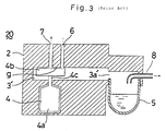
- This gas-liquid separator 20 is disposed between an engine (not shown) and said infrared analyzer and a body portion 2 is provided with a gas-liquid separating chamber 3', a centrifugal separator 4 and a drain pot 5.
- Said gas-liquid separating chamber 3' is a nearly rectangular hollow chamber and a sample gas-introducing pipe 6 connected with an exhaust pipe of said engine at one end thereof and a sample gas-discharging pipe 7 connected with a vacuum suction pump at one end thereof are arranged above the gas-liquid separating chamber 3'.
- Said centrifugal separator 4 comprises a motor 4a and a rotating plate 4b.
- Said motor 4a is arranged below the gas-liquid separating chamber 3' and an axis shaft line of the motor 4a coincides with an extending direction of said sample gas-discharging pipe 7.
- a small gap (g) is formed between said rotating plate 4b facing to openings of said sample gas-introducing pipe 6 and the sample gas-discharging pipe 7 and an upper surface of the gas-liquid separating chamber 3' so that said sample gas flowing into the gas-liquid separating chamber 3' through the sample gas-introducing pipe 6 may be efficiently flown out to the side of the sample gas-discharging pipe 7 without being retained within the gas-liquid separating chamber 3'.
- Said drain pot 5 is a detachable liquid-storing vessel made of glass and/or transparent plastics and installed by screwing in a screw member formed in an exhaust port 3a' of the gas-liquid separating chamber 3'.
- An end portion of a by-pass pipe 8 communicated with a vacuum suction pump for use in a by-pass (not shown) is extended above the drain pot 5 so that the gas-liquid separating chamber 3' may be kept at a negative pressure during the time when said vacuum suction pump for use in a by-pass is operated to introduce the separated liquid into the drain pot 5.
- sample gas-discharging pipe 7 is provided with a pressure regulator so that a gas pressure of the sample gas supplied to the infrared analyzer can be regulated when a gas pressure of the sample gas introduced into the sample gas-discharging pipe 7 is changed.
- both the vacuum suction pump for use in sampling and the vacuum suction pump for use in a by-pass are started to keep the gas-liquid separating chamber 3' at a negative pressure of for example about -2,94 N/cm2 (-0,3 Kgf/cm2).
- the centrifugal separator 4 is operated. Thereupon, a part of the exhaust gas discharged from said engine is introduced into the gas-liquid separating chamber 3' as the sample gas through the sample gas-introducing pipe 6.
- the drain pot 5 is suitably removed and the liquids and the like are dumped followed by installing the drain pot 5 again.
- the sample gas can be analyzed.
- the gas-liquid separating chamber 3' is adapted to be kept at the negative pressure and connected with said vacuum suction pump for use in a by-pass through a by-pass pipe 8.
- the suction pressure of the vacuum suction pump for use in a by-pass is not able to follow the internal pressure of the gas-liquid separating chamber 3' changing with a fluctuation of an output of the engine.
- the negative pressure condition is broken and thus it is not possible to suck the centrifugally separated liquid fractions toward the side of the drain pot 5.
- centrifugally separated liquid fractions do not fall into the drain pot 5 but a part thereof is flown into the side of the by-pass pipe 8 according to circumstances, Therefore, soot and the like is stucked to the by-pass pipe 8 to choke it in an extreme case.
- the present invention has been achieved in view of the above described problems and it is an object of the present invention to provide a gas-liquid separator capable of surely separating a gas from a liquid even though a pressure of a gas flowing into a gas-liquid separating chamber is fluctuated and requiring no troublesome maintenance and the like.
- a gas-liquid separator comprising a gas-liquid separating chamber provided with a gas-introducing pipe, a gas-discharging pipe and a by-pass pipe connected therewith, and a centrifugal separator for centrifugally separating a gas flown into said gas-liquid separating chamber through said gas-introducing pipe into a gas flown out toward the side of said gas-discharging pipe and a liquid, and in which liquid fractions centrifugally separated in said centrifugal separator are discharged toward the side of said by-pass pipe.
- the gas-liquid separator is characterized in that said gas-liquid separating chamber is provided with a communicating pipe communicated therewith and said communicating pipe is provided with a pressure regulator for regulating an internal pressure of the gas-liquid separating chamber to an appointed pressure depending upon a fluctuation of a gas pressure on the side of the gas-introducing pipe therein.
- the gas flown into the gas-liquid separating chamber through the gas-introducing pipe is separated into said gas and said liquid by means of the centrifugal separator. And, the gas is flown into the side of the gas-discharging pipe to be discharged while the liquid is discharged to the side of the by-pass pipe.
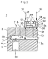
- a gas-liquid separator 1 according to Fig. 1 comprises a body portion 2 provided with a pressure regulator 9. Further, a pipe end of a by-pass pipe 8 communicating with a vacuum suction pump for use in a by-pass is connected with a discharge port 3a of a gas-liquid separating chamber 3.
- Said pressure regulator 9 comprises an upper chamber 9c and a lower chamber 9d formed by disposing a diaphragm 10 at a portion where a case body 9a is spliced to a cover member 9b and is fixedly mounted on an upper surface 2a of said body portion 2.
- Two pieces of spring members 11, 11 are disposed between an upper surface of said diaphragm 10 and an inner surface of said cover member 9b.
- An upper end of a valve member 12 having a spherical member 12b fixed on a short axis 12a is fixedly mounted with said short axis 12a on a center of a lower surface of the diaphragm 10.
- the cover member 9b is provided with an opening 9e communicating with an air and also said case body 9a is provided with two openings 9f, 9g so that one opening 9f may communicate with said gas-liquid separating chamber 3 through a communicating pipe 13.
- the other opening 9g communicates with an opening 14a of a hollow portion 14 formed in an upper portion of the body portion 2, said short axis 12a of said valve member 12 being inserted into said opening 14a and said opening 9g, and said spherical member 12b being arranged within said hollow portion 14.
- An air-supply pipe 15 provided with an air-release means or an air filter is connected with the hollow portion 14 at an end portion thereof to supply the pressure regulator 9 with a pressure-regulating gas from an air through the hollow portion 14.
- the pressure regulator 9 is adapted to regulate a quantity of said pressure-regulating gas supplied depending upon the pressure fluctuation of the gas exhausted at a start of the engine.
- a force of said spring members are regulated so that the diaphragm 10 may be horizontally extended to form a small gap between the opening 14a of the hollow portion 14 and the spherical member 12b at a stationary pressure.
- a vacuum suction pump for use in sampling and said vacuum suction pump for use in a by-pass are started to keep an inside of the gas-liquid separating chamber 3 at a negative pressure of about -2,94 N/cm2 (-0,3 Kgf/cm2).
- the pressure regulator 9 is supplied with the pressure-regulating gas from an air through said air-supply pipe 15 and the hollow portion 14.
- a centrifugal separator 4 is started. Further, a part of an exhaust gas exhausted from the engine is introduced into the gas-liquid separator 3 as a sample gas through a sample gas-introducing pipe 6. At this time, liquids, such as water drops, and small particulate solids, such as soot, contained in said sample gas come into collision with a rotary member 4b rotating with high speed to be blown off by a centrifugal separation.
- the sample gas is separated into liquids and gases in the above described manner, the sample gas containing no liquid is sucked by said vacuum suction pump for use as a sample to be introduced into an infrared analyzer from said small gap (g) through a sample gas-discharging pipe 7. And, ingredients are analyzed in said infrared analyzer.
- the pressure at a sample inlet communicating with the gas-introducing pipe 6 is varied within a range of about -0,98 to 9,8 N/cm2 (-0,1 to 1 Kgf/cm2) due to the fluctuation of the output of the engine and thus also the internal pressure of the gas-liquid separating chamber 3 begins to be varied but a pressure in the vicinity of said exhaust port 3a, which is a pressure-regulating point of the gas-liquid separating chamber 3, is regulated to keep the inside of the gas-liquid separating chamber 3 at a constant pressure.
- the desired regulated pressure is P
- the atmospheric pressure being p0
- the area of the diaphragm is A
- the force of the springs being kx
- the diaphragm 10 of the pressure regulator 9 is bent upward to move up the valve member 12. At this time, the diaphragm 10 is deformed depending upon the fluctuation of pressure to reduce an openness between the spherical member 12b of the valve member 12 and the opening 14a, whereby reducing a quantity of the pressure-regulating gas flown into the pressure-regulator 9. At this time, the quantity of the pressure-regulating gas flown into the exhaust port 3a through said communicating pipe 13 from the pressure regulator 9 is reduced with an increase of the sample gas flown into the gas-liquid separating chamber 3.
- the internal pressure of the pressure-regulator 9 is increased to cut off the supply of the pressure-regulating gas by means of the valve member 12, whereby a pressure-regulating capacity is lost.
- the force of the springs, the suction force of the vacuum pumps and the like can previously be regulated so that said supply of the pressure-regulating gas may not be cut off.
- the pressure-regulator is adapted to always satisfactorily operate.
- the valve member 12 is opened to increase the quantity of the pressure-regulating gas supplied. Accordingly, the flow rate at the pressure-regulating point can be always kept nearly unchanged and thus the discharge of the liquids separated and the supply of the sample gas to the infrared analyzer are not influenced.
- the gas-liquid separator 1 is disposed between the engine and the infrared analyzer in order to analyze an exhaust gas from a motor vehicle in the above described preferred embodiment, the present invention is not limited by this. That is the present invention can be widely applied to various kinds of apparatus for centrifugally separating a liquid-containing gas.
- the pressure regulator 9 may be detachably mounted on the body portion 2, as shown in Fig. 2.
- reference numeral 30 designates screw holes and reference numeral 31 designates screws.
- the gas-liquid separator according to the present invention is provided with a pressure regulator communicating with the gas-liquid separating chamber, so that the internal pressure of the gas-liquid separating chamber can be kept nearly unchanged even though the gas pressure on the side of the gas introducing pipe is fluctuated. Accordingly, the centrifugal separation of the gas can be appropriately achieved and thus the liquids and the like can be discharged without being retained in the by-pass pipe and the like, whereby the problems of the choking and staining can be prevented. In addition, the troublesome maintenance, such as the removal of the drain pot followed by the dumping of the liquids stored in the drain pot after every appointed time, becomes unnecessary.
Landscapes
- Health & Medical Sciences (AREA)
- Life Sciences & Earth Sciences (AREA)
- Chemical & Material Sciences (AREA)
- Engineering & Computer Science (AREA)
- Physics & Mathematics (AREA)
- General Health & Medical Sciences (AREA)
- Pathology (AREA)
- Biomedical Technology (AREA)
- Molecular Biology (AREA)
- Immunology (AREA)
- General Physics & Mathematics (AREA)
- Food Science & Technology (AREA)
- Medicinal Chemistry (AREA)
- Analytical Chemistry (AREA)
- Biochemistry (AREA)
- Chemical Kinetics & Catalysis (AREA)
- Urology & Nephrology (AREA)
- Hematology (AREA)
- Biophysics (AREA)
- Combustion & Propulsion (AREA)
- Centrifugal Separators (AREA)
- Sampling And Sample Adjustment (AREA)
- Separating Particles In Gases By Inertia (AREA)
Claims (7)
- Gas-Flüssigkeits-Trennvorrichtung (1), mit einer Gas-Flüssigkeits-Trennkammer (3), die mit einer Gas-Einströmleitung (6), einer Gas-Ausströmleitung (7) und einem Umgehungsrohr (8) verbunden ist, und mit einer Zentrifugaltrennvorrichtung (4a bis 4c) zum zentrifugalen Trennen eines in die Gas-Flüssigkeits-Trennkammer (3) durch die Gas-Einströmleitung (6) einströmenden Gases in ein zur Seite der Gas-Ausströmleitung (7) strömendes Gas sowie in eine Flüssigkeit, die durch die Zentrifugaltrennvorrichtung (4a bis 4c) zur Seite des Umgehungsrohrs (8) ausgestoßen wird, dadurch gekennzeichnet, daß- die Gas-Flüssigkeits-Trennkammer (3) mit einer kommunizierenden Leitung (13) verbunden ist, und- die kommunizierende Leitung (13) mit einem Druckregler (9) zum Regulieren eines Innendrucks der Gas-Flüssigkeits-Trennkammer (3) auf einen festgelegten Druckje nach Fluktuation des Gasdrucks auf der Seite der Gas-Einströmleitung (6) ausgestattet ist.
- Gas-Flüssigkeits-Trennvorrichtung nach Anspruch 1, dadurch gekenn zeichnet, daß der Druckregler (9) durch ein Diaphragma (10) in eine erste Kammer (9c), in der ein konstanter Druck herrscht sowie in eine mit der kommunizierenden Leitung (13) verbundene zweite Kammer (9d) unterteilt ist, welche über eine weitere Öffnung (9g) mit einem Hohlraum (14) in Verbindung steht, der ein mit dem Diaphragma (10) verbundenes Ventilelement (12) enthält, um die Öffnung (9g) in Abhängigkeit eines Steuergasdrucks im Hohlraum (14) zu öffnen oder zu schließen.
- Gas-Flüssigkeits-Trennvorrichtung nach Anspruch 2, dadurch ge kennzeichnet, daß die Fluktuation des Steuergasdrucks der Fluktuation des Gasdrucks an der Seite der Gas-Einströmleitung (6) entspricht.
- Gas-Flüssigkeits-Trennvorrichtung nach einem der Ansprüche 2 oder 3, dadurch gekennzeichnet, daß Beaufschlagungseinrichtungen (11) zum Beaufschlagen des Diaphragmas (10) mit einer vorbestimmten Kraft vorhanden sind.
- Gas-Flüssigkeits-Trennvorrichtung nach einem der Ansprüche 2 bis 4, dadurch gekennzeichnet, daß der Hohlraum (14) in einem Trägerelement (2) vorhanden ist, mit dem der Druckregler (9) verbunden ist.
- Gas-Flüssigkeits-Trennvorrichtung nach einem der Ansprüche 2 bis 4, dadurch gekennzeichnet, daß der Hohlraum (14) durch eine dritte Kammer des Druckreglers (9) gebildet ist.
- Gas-Flüssigkeits-Trennvorrichtung nach Anspruch 6, dadurch gekennzeichnet, daß der Druckregler (9) loslösbar am Trägerelement (2) montiert ist.
Applications Claiming Priority (2)
| Application Number | Priority Date | Filing Date | Title |
|---|---|---|---|
| JP27884/90 | 1990-02-07 | ||
| JP2788490A JP2841224B2 (ja) | 1990-02-07 | 1990-02-07 | 気液分離器 |
Publications (2)
| Publication Number | Publication Date |
|---|---|
| EP0441348A1 EP0441348A1 (de) | 1991-08-14 |
| EP0441348B1 true EP0441348B1 (de) | 1994-04-20 |
Family
ID=12233323
Family Applications (1)
| Application Number | Title | Priority Date | Filing Date |
|---|---|---|---|
| EP91101615A Expired - Lifetime EP0441348B1 (de) | 1990-02-07 | 1991-02-06 | Gas-Flüssigkeitsabscheider |
Country Status (4)
| Country | Link |
|---|---|
| US (1) | US5147426A (de) |
| EP (1) | EP0441348B1 (de) |
| JP (1) | JP2841224B2 (de) |
| DE (1) | DE69101722T2 (de) |
Families Citing this family (9)
| Publication number | Priority date | Publication date | Assignee | Title |
|---|---|---|---|---|
| US5709082A (en) * | 1994-06-27 | 1998-01-20 | General Motors Corporation | Modulation schemes for on-board diagnostic exhaust system |
| US5589629A (en) * | 1995-04-25 | 1996-12-31 | Quinn; Stephen J. | Method and apparatus for testing vehicle exhaust emissions |
| JP2008521596A (ja) * | 2004-11-30 | 2008-06-26 | ファイア テクノロジーズ、インコーポレイテッド | 接触装置および接触方法ならびにそれらの使用 |
| JP3832498B1 (ja) * | 2005-06-24 | 2006-10-11 | オムロン株式会社 | 流量測定装置 |
| JP4702666B2 (ja) * | 2005-07-20 | 2011-06-15 | Smc株式会社 | ドレンセパレータ |
| US7875109B1 (en) * | 2007-03-08 | 2011-01-25 | A+ Manufacturing, Llc | Integral flow restrictor valve |
| CN101995449B (zh) * | 2009-08-21 | 2014-02-05 | 中国石油化工股份有限公司 | 乙炔气体压力敏感性爆炸测试装置 |
| DE102014101915B4 (de) * | 2014-02-14 | 2024-08-01 | Avl Analytical Technologies Gmbh | Vorrichtung und Verfahren zur Bestimmung der Konzentration zumindest eines Gases in einem Probengasstrom mittels Infrarotabsorptionsspektroskopie |
| CN110776967B (zh) * | 2019-11-13 | 2021-03-02 | 新奥(舟山)液化天然气有限公司 | 一种液态天然气分离回收装置 |
Family Cites Families (11)
| Publication number | Priority date | Publication date | Assignee | Title |
|---|---|---|---|---|
| DE1000515B (de) * | 1953-05-26 | 1957-01-10 | Licentia Gmbh | Elektrizitaetszaehler mit Trommelanker |
| DE1098873B (de) * | 1957-02-28 | 1961-02-02 | Separator Ab | Anordnung zum Konstanthalten des Stroemungswiderstandes in einer Zentrifuge |
| US3451421A (en) * | 1966-07-22 | 1969-06-24 | Controls Co Of America | Convertible modulating pressure regulator |
| US3593023A (en) * | 1968-09-18 | 1971-07-13 | Beckman Instruments Inc | Apparatus and method for exhaust analysis |
| US3586037A (en) * | 1969-05-26 | 1971-06-22 | Victor Equipment Co | Single stage, compensated pressure regulator |
| DE2215641A1 (de) * | 1972-03-30 | 1973-10-04 | Bosch Gmbh Robert | Vorrichtung zur ermittlung der zusammensetzung des abgases einer brennkraftmaschine |
| US4160373A (en) * | 1974-12-19 | 1979-07-10 | United Technologies Corporation | Vehicle exhaust gas analysis system with gas blockage interlock |
| JPS58184531A (ja) * | 1982-04-21 | 1983-10-28 | Horiba Ltd | ガス分流比の測定又は制御装置 |
| JPS59202043A (ja) * | 1983-04-30 | 1984-11-15 | Horiba Ltd | デイ−ゼル排気ガス中の煤粒子測定装置 |
| US4678488A (en) * | 1985-05-02 | 1987-07-07 | Sensors, Inc. | Liquid separator for gas analyzer |
| JPS62185165A (ja) * | 1986-02-10 | 1987-08-13 | Horiba Ltd | パ−ティキュレ−ト分析装置 |
-
1990
- 1990-02-07 JP JP2788490A patent/JP2841224B2/ja not_active Expired - Fee Related
-
1991
- 1991-02-04 US US07/656,418 patent/US5147426A/en not_active Expired - Fee Related
- 1991-02-06 EP EP91101615A patent/EP0441348B1/de not_active Expired - Lifetime
- 1991-02-06 DE DE69101722T patent/DE69101722T2/de not_active Expired - Fee Related
Also Published As
| Publication number | Publication date |
|---|---|
| DE69101722D1 (de) | 1994-05-26 |
| DE69101722T2 (de) | 1994-11-10 |
| EP0441348A1 (de) | 1991-08-14 |
| US5147426A (en) | 1992-09-15 |
| JP2841224B2 (ja) | 1998-12-24 |
| JPH03232512A (ja) | 1991-10-16 |
Similar Documents
| Publication | Publication Date | Title |
|---|---|---|
| EP0441348B1 (de) | Gas-Flüssigkeitsabscheider | |
| CA2105661A1 (en) | A device and a method for separating liquid samples | |
| EP1322934B1 (de) | Gerät zur akkumulation von in der luft enthaltenen partikeln | |
| US4878923A (en) | Apparatus for removing oil from a compressed gas flow | |
| US4370971A (en) | Apparatus for removing contaminants from crankcase emissions | |
| US20040074828A1 (en) | Cyclone separator suitable for variable fluid flow rates | |
| KR102568850B1 (ko) | 유체 시스템 및 유체 시스템을 포함하는 샘플 처리기 | |
| CA2299629A1 (en) | Method and apparatus for separating particulate matter from a liquid specimen | |
| JPH10318150A5 (de) | ||
| FI79196B (fi) | Anordning foer provtagning ur substans innehaollande fast aemne. | |
| US4842622A (en) | Gas/liquid/solids separator | |
| US5387278A (en) | Air-liquid separator assembly and system | |
| GB2288344A (en) | Dust Sampling Device | |
| CA1254059A (en) | System for automatic sampling and sample conveyance for analysis | |
| SU1597221A1 (ru) | Барабан центробежного сепаратора | |
| JPH0445786B2 (de) | ||
| EP0447992A1 (de) | Gasflüssigkeitsabscheider | |
| US4673295A (en) | Method and an apparatus for performing routine analyses such as polarographic or spectrophotometric analysis | |
| SU1357750A1 (ru) | Способ отбора проб поверхностного микросло жидкости и устройство дл его осуществлени | |
| EP0352941A3 (de) | Gerät und Verfahren zur Durchflusssteuerung | |
| JP2001058105A (ja) | 脱気装置 | |
| JP2002066600A (ja) | 固形物分離装置 | |
| FI82145B (fi) | System foer automatisk uttagning och transport av prov. | |
| JPS61146311A (ja) | 気体分離装置 | |
| WO1994012263A1 (en) | A device for dewatering and/or transport of screening or sludge material |
Legal Events
| Date | Code | Title | Description |
|---|---|---|---|
| PUAI | Public reference made under article 153(3) epc to a published international application that has entered the european phase |
Free format text: ORIGINAL CODE: 0009012 |
|
| AK | Designated contracting states |
Kind code of ref document: A1 Designated state(s): DE FR GB |
|
| 17P | Request for examination filed |
Effective date: 19910920 |
|
| 17Q | First examination report despatched |
Effective date: 19930721 |
|
| GRAA | (expected) grant |
Free format text: ORIGINAL CODE: 0009210 |
|
| AK | Designated contracting states |
Kind code of ref document: B1 Designated state(s): DE FR GB |
|
| REF | Corresponds to: |
Ref document number: 69101722 Country of ref document: DE Date of ref document: 19940526 |
|
| ET | Fr: translation filed | ||
| PLBE | No opposition filed within time limit |
Free format text: ORIGINAL CODE: 0009261 |
|
| STAA | Information on the status of an ep patent application or granted ep patent |
Free format text: STATUS: NO OPPOSITION FILED WITHIN TIME LIMIT |
|
| 26N | No opposition filed | ||
| PG25 | Lapsed in a contracting state [announced via postgrant information from national office to epo] |
Ref country code: FR Effective date: 19951031 |
|
| REG | Reference to a national code |
Ref country code: FR Ref legal event code: ST |
|
| PGFP | Annual fee paid to national office [announced via postgrant information from national office to epo] |
Ref country code: DE Payment date: 20010129 Year of fee payment: 11 |
|
| PGFP | Annual fee paid to national office [announced via postgrant information from national office to epo] |
Ref country code: GB Payment date: 20010131 Year of fee payment: 11 |
|
| REG | Reference to a national code |
Ref country code: GB Ref legal event code: IF02 |
|
| PG25 | Lapsed in a contracting state [announced via postgrant information from national office to epo] |
Ref country code: GB Free format text: LAPSE BECAUSE OF NON-PAYMENT OF DUE FEES Effective date: 20020206 |
|
| PG25 | Lapsed in a contracting state [announced via postgrant information from national office to epo] |
Ref country code: DE Free format text: LAPSE BECAUSE OF NON-PAYMENT OF DUE FEES Effective date: 20020903 |
|
| GBPC | Gb: european patent ceased through non-payment of renewal fee |
Effective date: 20020206 |