EP0441401A1 - Exhaust gas purification system for an internal combustion engine - Google Patents
Exhaust gas purification system for an internal combustion engine Download PDFInfo
- Publication number
- EP0441401A1 EP0441401A1 EP91101802A EP91101802A EP0441401A1 EP 0441401 A1 EP0441401 A1 EP 0441401A1 EP 91101802 A EP91101802 A EP 91101802A EP 91101802 A EP91101802 A EP 91101802A EP 0441401 A1 EP0441401 A1 EP 0441401A1
- Authority
- EP
- European Patent Office
- Prior art keywords
- fuel
- hydrocarbons
- boiling points
- low boiling
- exhaust gas
- Prior art date
- Legal status (The legal status is an assumption and is not a legal conclusion. Google has not performed a legal analysis and makes no representation as to the accuracy of the status listed.)
- Granted
Links
Images



Classifications
-
- F—MECHANICAL ENGINEERING; LIGHTING; HEATING; WEAPONS; BLASTING
- F01—MACHINES OR ENGINES IN GENERAL; ENGINE PLANTS IN GENERAL; STEAM ENGINES
- F01N—GAS-FLOW SILENCERS OR EXHAUST APPARATUS FOR MACHINES OR ENGINES IN GENERAL; GAS-FLOW SILENCERS OR EXHAUST APPARATUS FOR INTERNAL-COMBUSTION ENGINES
- F01N3/00—Exhaust or silencing apparatus having means for purifying, rendering innocuous, or otherwise treating exhaust
- F01N3/08—Exhaust or silencing apparatus having means for purifying, rendering innocuous, or otherwise treating exhaust for rendering innocuous
- F01N3/10—Exhaust or silencing apparatus having means for purifying, rendering innocuous, or otherwise treating exhaust for rendering innocuous by thermal or catalytic conversion of noxious components of exhaust
- F01N3/24—Exhaust or silencing apparatus having means for purifying, rendering innocuous, or otherwise treating exhaust for rendering innocuous by thermal or catalytic conversion of noxious components of exhaust characterised by constructional aspects of converting apparatus
- F01N3/36—Arrangements for supply of additional fuel
-
- B—PERFORMING OPERATIONS; TRANSPORTING
- B01—PHYSICAL OR CHEMICAL PROCESSES OR APPARATUS IN GENERAL
- B01D—SEPARATION
- B01D53/00—Separation of gases or vapours; Recovering vapours of volatile solvents from gases; Chemical or biological purification of waste gases, e.g. engine exhaust gases, smoke, fumes, flue gases, aerosols
- B01D53/34—Chemical or biological purification of waste gases
- B01D53/92—Chemical or biological purification of waste gases of engine exhaust gases
- B01D53/94—Chemical or biological purification of waste gases of engine exhaust gases by catalytic processes
- B01D53/9445—Simultaneously removing carbon monoxide, hydrocarbons or nitrogen oxides making use of three-way catalysts [TWC] or four-way-catalysts [FWC]
- B01D53/945—Simultaneously removing carbon monoxide, hydrocarbons or nitrogen oxides making use of three-way catalysts [TWC] or four-way-catalysts [FWC] characterised by a specific catalyst
-
- B—PERFORMING OPERATIONS; TRANSPORTING
- B01—PHYSICAL OR CHEMICAL PROCESSES OR APPARATUS IN GENERAL
- B01D—SEPARATION
- B01D53/00—Separation of gases or vapours; Recovering vapours of volatile solvents from gases; Chemical or biological purification of waste gases, e.g. engine exhaust gases, smoke, fumes, flue gases, aerosols
- B01D53/34—Chemical or biological purification of waste gases
- B01D53/92—Chemical or biological purification of waste gases of engine exhaust gases
- B01D53/94—Chemical or biological purification of waste gases of engine exhaust gases by catalytic processes
- B01D53/9495—Controlling the catalytic process
-
- F—MECHANICAL ENGINEERING; LIGHTING; HEATING; WEAPONS; BLASTING
- F01—MACHINES OR ENGINES IN GENERAL; ENGINE PLANTS IN GENERAL; STEAM ENGINES
- F01N—GAS-FLOW SILENCERS OR EXHAUST APPARATUS FOR MACHINES OR ENGINES IN GENERAL; GAS-FLOW SILENCERS OR EXHAUST APPARATUS FOR INTERNAL-COMBUSTION ENGINES
- F01N3/00—Exhaust or silencing apparatus having means for purifying, rendering innocuous, or otherwise treating exhaust
- F01N3/08—Exhaust or silencing apparatus having means for purifying, rendering innocuous, or otherwise treating exhaust for rendering innocuous
- F01N3/10—Exhaust or silencing apparatus having means for purifying, rendering innocuous, or otherwise treating exhaust for rendering innocuous by thermal or catalytic conversion of noxious components of exhaust
- F01N3/18—Exhaust or silencing apparatus having means for purifying, rendering innocuous, or otherwise treating exhaust for rendering innocuous by thermal or catalytic conversion of noxious components of exhaust characterised by methods of operation; Control
- F01N3/20—Exhaust or silencing apparatus having means for purifying, rendering innocuous, or otherwise treating exhaust for rendering innocuous by thermal or catalytic conversion of noxious components of exhaust characterised by methods of operation; Control specially adapted for catalytic conversion
- F01N3/206—Adding periodically or continuously substances to exhaust gases for promoting purification, e.g. catalytic material in liquid form, NOx reducing agents
- F01N3/2066—Selective catalytic reduction [SCR]
-
- F—MECHANICAL ENGINEERING; LIGHTING; HEATING; WEAPONS; BLASTING
- F01—MACHINES OR ENGINES IN GENERAL; ENGINE PLANTS IN GENERAL; STEAM ENGINES
- F01N—GAS-FLOW SILENCERS OR EXHAUST APPARATUS FOR MACHINES OR ENGINES IN GENERAL; GAS-FLOW SILENCERS OR EXHAUST APPARATUS FOR INTERNAL-COMBUSTION ENGINES
- F01N2240/00—Combination or association of two or more different exhaust treating devices, or of at least one such device with an auxiliary device, not covered by indexing codes F01N2230/00 or F01N2250/00, one of the devices being
- F01N2240/02—Combination or association of two or more different exhaust treating devices, or of at least one such device with an auxiliary device, not covered by indexing codes F01N2230/00 or F01N2250/00, one of the devices being a heat exchanger
-
- F—MECHANICAL ENGINEERING; LIGHTING; HEATING; WEAPONS; BLASTING
- F01—MACHINES OR ENGINES IN GENERAL; ENGINE PLANTS IN GENERAL; STEAM ENGINES
- F01N—GAS-FLOW SILENCERS OR EXHAUST APPARATUS FOR MACHINES OR ENGINES IN GENERAL; GAS-FLOW SILENCERS OR EXHAUST APPARATUS FOR INTERNAL-COMBUSTION ENGINES
- F01N2240/00—Combination or association of two or more different exhaust treating devices, or of at least one such device with an auxiliary device, not covered by indexing codes F01N2230/00 or F01N2250/00, one of the devices being
- F01N2240/30—Combination or association of two or more different exhaust treating devices, or of at least one such device with an auxiliary device, not covered by indexing codes F01N2230/00 or F01N2250/00, one of the devices being a fuel reformer
-
- F—MECHANICAL ENGINEERING; LIGHTING; HEATING; WEAPONS; BLASTING
- F01—MACHINES OR ENGINES IN GENERAL; ENGINE PLANTS IN GENERAL; STEAM ENGINES
- F01N—GAS-FLOW SILENCERS OR EXHAUST APPARATUS FOR MACHINES OR ENGINES IN GENERAL; GAS-FLOW SILENCERS OR EXHAUST APPARATUS FOR INTERNAL-COMBUSTION ENGINES
- F01N2370/00—Selection of materials for exhaust purification
- F01N2370/02—Selection of materials for exhaust purification used in catalytic reactors
- F01N2370/04—Zeolitic material
-
- F—MECHANICAL ENGINEERING; LIGHTING; HEATING; WEAPONS; BLASTING
- F01—MACHINES OR ENGINES IN GENERAL; ENGINE PLANTS IN GENERAL; STEAM ENGINES
- F01N—GAS-FLOW SILENCERS OR EXHAUST APPARATUS FOR MACHINES OR ENGINES IN GENERAL; GAS-FLOW SILENCERS OR EXHAUST APPARATUS FOR INTERNAL-COMBUSTION ENGINES
- F01N2610/00—Adding substances to exhaust gases
- F01N2610/03—Adding substances to exhaust gases the substance being hydrocarbons, e.g. engine fuel
-
- F—MECHANICAL ENGINEERING; LIGHTING; HEATING; WEAPONS; BLASTING
- F01—MACHINES OR ENGINES IN GENERAL; ENGINE PLANTS IN GENERAL; STEAM ENGINES
- F01N—GAS-FLOW SILENCERS OR EXHAUST APPARATUS FOR MACHINES OR ENGINES IN GENERAL; GAS-FLOW SILENCERS OR EXHAUST APPARATUS FOR INTERNAL-COMBUSTION ENGINES
- F01N2610/00—Adding substances to exhaust gases
- F01N2610/10—Adding substances to exhaust gases the substance being heated, e.g. by heating tank or supply line of the added substance
-
- F—MECHANICAL ENGINEERING; LIGHTING; HEATING; WEAPONS; BLASTING
- F01—MACHINES OR ENGINES IN GENERAL; ENGINE PLANTS IN GENERAL; STEAM ENGINES
- F01N—GAS-FLOW SILENCERS OR EXHAUST APPARATUS FOR MACHINES OR ENGINES IN GENERAL; GAS-FLOW SILENCERS OR EXHAUST APPARATUS FOR INTERNAL-COMBUSTION ENGINES
- F01N2610/00—Adding substances to exhaust gases
- F01N2610/14—Arrangements for the supply of substances, e.g. conduits
- F01N2610/1453—Sprayers or atomisers; Arrangement thereof in the exhaust apparatus
- F01N2610/146—Control thereof, e.g. control of injectors or injection valves
-
- F—MECHANICAL ENGINEERING; LIGHTING; HEATING; WEAPONS; BLASTING
- F01—MACHINES OR ENGINES IN GENERAL; ENGINE PLANTS IN GENERAL; STEAM ENGINES
- F01N—GAS-FLOW SILENCERS OR EXHAUST APPARATUS FOR MACHINES OR ENGINES IN GENERAL; GAS-FLOW SILENCERS OR EXHAUST APPARATUS FOR INTERNAL-COMBUSTION ENGINES
- F01N2900/00—Details of electrical control or of the monitoring of the exhaust gas treating apparatus
- F01N2900/06—Parameters used for exhaust control or diagnosing
- F01N2900/08—Parameters used for exhaust control or diagnosing said parameters being related to the engine
-
- F—MECHANICAL ENGINEERING; LIGHTING; HEATING; WEAPONS; BLASTING
- F02—COMBUSTION ENGINES; HOT-GAS OR COMBUSTION-PRODUCT ENGINE PLANTS
- F02B—INTERNAL-COMBUSTION PISTON ENGINES; COMBUSTION ENGINES IN GENERAL
- F02B1/00—Engines characterised by fuel-air mixture compression
- F02B1/02—Engines characterised by fuel-air mixture compression with positive ignition
- F02B1/04—Engines characterised by fuel-air mixture compression with positive ignition with fuel-air mixture admission into cylinder
-
- F—MECHANICAL ENGINEERING; LIGHTING; HEATING; WEAPONS; BLASTING
- F02—COMBUSTION ENGINES; HOT-GAS OR COMBUSTION-PRODUCT ENGINE PLANTS
- F02B—INTERNAL-COMBUSTION PISTON ENGINES; COMBUSTION ENGINES IN GENERAL
- F02B3/00—Engines characterised by air compression and subsequent fuel addition
- F02B3/06—Engines characterised by air compression and subsequent fuel addition with compression ignition
-
- Y—GENERAL TAGGING OF NEW TECHNOLOGICAL DEVELOPMENTS; GENERAL TAGGING OF CROSS-SECTIONAL TECHNOLOGIES SPANNING OVER SEVERAL SECTIONS OF THE IPC; TECHNICAL SUBJECTS COVERED BY FORMER USPC CROSS-REFERENCE ART COLLECTIONS [XRACs] AND DIGESTS
- Y02—TECHNOLOGIES OR APPLICATIONS FOR MITIGATION OR ADAPTATION AGAINST CLIMATE CHANGE
- Y02T—CLIMATE CHANGE MITIGATION TECHNOLOGIES RELATED TO TRANSPORTATION
- Y02T10/00—Road transport of goods or passengers
- Y02T10/10—Internal combustion engine [ICE] based vehicles
- Y02T10/12—Improving ICE efficiencies
Definitions
- the present invention relates to an exhaust gas purification system for an internal combustion engine provided with a catalyst capable of reducing nitrogen oxides (hereinafter, NOx) under oxidizing conditions and in the presence of hydrocarbons. More particularly, the present invention relates to an exhaust gas purification system wherein hydrocarbons having low boiling points produced from a fuel for the engine is supplied to the catalyst to increase a NOx purification rate of the catalyst.
- NOx nitrogen oxides
- Japanese Patent Publication HEI 1-130735 discloses a zeolite catalyst carrying transition metals which can reduce NOx in the presence of hydrocarbons.
- Japanese Patent Publication SHO 63-283727 proposes an apparatus for supplying hydocarbons to an engine exhaust conduit upstream of the zeolite type catalyst.
- the apparatus includes a particular hydrocarbon source different from the fuel for the engine, and installation of such particular hydrocarbon source would increase cost.
- hydrocarbons effective to reduce NOx have a relatively small carbon number (for example, 3-6) per molecule.
- diesel fuel light oil
- hydrocarbons having a large carbon number (for example, more than 10) per molecule As a result, even if the fuel is supplied to the zeolite type catalyst, significant increase of NOx purification rate cannot be expected.
- An object of the invention is to improve NOx purification rate of a zeolite type NOx reduction catalyst installed in an exhaust system of an internal combustion engine by supplying hydrocarbons having low boiling points (that is, hydrocarbons having a relatively small carbon number per molecule) without installing a particular hydrocarbon source different from the fuel used for combustion in the engine.
- an exhaust gas purification system for an internal combustion engine in accordance with the present invention.
- the system includes an internal combustion engine capable of fuel combustion at lean air-fuel ratios, a catalyst installed in an exhaust conduit of the engine and constructed of zeolite carrying at least one kind of metal selected from transition metals and noble metals to reduce nitrogen oxides included in exhaust gas from the engine under oxidizing conditions and in the presence of hydrocarbons (hereinafter, a lean NOx catalyst), HC producing means for producing hydrocarbons of low boiling points from fuel for the engine, and HC supply means for supplying the hydrocarbons of low boiling points produced by the HC producing means to the exhaust conduit upstream of the lean NOx catalyst.
- a lean NOx catalyst hydrocarbons
- HC producing means for producing hydrocarbons of low boiling points from fuel for the engine
- HC supply means for supplying the hydrocarbons of low boiling points produced by the HC producing means to the exhaust conduit upstream of the lean NOx catalyst.
- the HC producing means produces hydrocarbons of low boiling points by any one of cracking, fractional distillation, and combined cracking and fractional distillation, utilizing at least a portion of the fuel for combustion in the engine in the case of diesel engines.
- the produced hydrocarbons of low boiling points are supplied to the lean NOx catalyst to increase the NOx purification rate or NOx reduction rate of the lean NOx catalyst.
- the hydrocarbons of low boiling points are produced by cracking at least a portion of the engine fuel (diesel fuel), as illustrated in FIGS. 1-7.
- hydrocarbons of low boiling points are produced through fractional distillation of the fuel, as illustrated in FIG. 8.
- hydrocarbons of low boiling points are produced through combined cracking and fractional distillation of the fuel, as illustrated in FIG. 9.
- an engine 1 capable of fuel combustion at lean air-fuel ratios comprises a diesel engine.
- Diesel fuel (light oil) is supplied by a fuel pump 2 and is injected into each cylinder of the engine through a respective fuel injection nozzle 5.
- An exhaust conduit 16 is connected to the engine, and a lean NOx catalyst 3 is installed in the exhaust conduit 16 for purifying the exhaust gas. Since the diesel engine 1 is operated at lean air-fuel ratios, the exhaust gas contains excess oxygen, so that the lean NOx catalyst 3 can reduce NOx in the presence of HC.
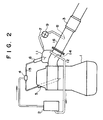
- An exhaust manifold 14 of the engine is provided with a fuel cracking chamber 11, which is located preferably above the exhaust manifold 14.
- a manifold wall 17 separating the fuel cracking chamber 11 from the interior of the exhaust manifold 14 has a large heat transfer area so that the fuel cracking chamber 11 can be heated to a temperature above 500°C.
- a fuel supply pipe 18 extending from the fuel pump 2 to each fuel injection nozzle 5 has a diverging portion such as a T-fitting 4 from which a branch pipe 15 extends to the fuel cracking chamber 11 so that a portion of the diesel fuel is fed into the fuel cracking chamber 11 through an injection nozzle 6 mounted on the fuel cracking chamber 11.
- the fuel pump 2, the diverging portion 4, the branch pipe 15, the injection nozzle 6, and the fuel cracking chamber 11 constitute an HC producing means for producing hydrocarbons of low boiling points by cracking a portion of the engine fuel.
- a cracked-fuel supply pipe 7 extends from the fuel cracking chamber 11 to a cracked-fuel injection port 8 located in the exhaust conduit 16 upstream of the lean NOx catalyst 3.
- a flow control valve 9 is installed in the cracked-fuel supply pipe 7. Opening degree of the flow control valve 9 is controlled by an actuator 10 which constitutes, for example, a duty control solenoid.
- the cracked-fuel supply pipe 7, the cracked-fuel injection portion 8, the flow control valve 9, and the actuator 10 constitute an HC supply means for supplying the cracked fuel (hydrocarbons of low boiling points) to the exhaust conduit 16 upstream of the lean NOx catalyst 3.
- a fuel return pipe 12 for returning excess fuel remaining in the fuel cracking chamber 11 (fuel which has not been fed to the lean NOx catalyst 3) to the fuel pump 2 is provided at the bottom of the fuel cracking chamber 11.
- An electronic control unit 13 (hereinafter, ECU) is provided to control the quantity of the cracked fuel fed to the exhaust conduit upstream of the lean NOx catalyst 3.
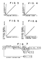
- the ECU 13 controls the flow control valve 9 via the actuator 10 as a function of engine speed Ne, so that the opening degree of the flow control valve and thus quantity of fuel supplied increase with increasing engine speed, as illustrated in FIG. 5 and FIG. 3, respectively.
- the ECU 13 controls the flow control valve 9 as a function of engine load Te, so that the opening degree of the flow control valve and thus the quantity of the supplied fuel increase with increasing engine load (that is, quantity of fuel injected into the cylinders or opening degree of a throttle valve), as illustrated in FIG. 6 and FIG. 4, respectively.
- the fuel injectors 5 are electromagnetically operated, and the injection timing and fuel injection quantity thereof is controlled by the ECU 13.
- a portion (about 10 %) of the diesel fuel is fed to the fuel cracking chamber 11 though the injection nozzles 6.
- This fuel receives heat via the manifold wall 17 from the exhaust gas flowing inside the exhaust manifold and is cracked into hydrocarbons having small carbon numbers (for examples, 3-6) per molecule and therefore, hydrocarbons of low boiling points.
- This cracking will be caused when the manifold wall is heated to a temperature above about 500°C.
- a coating of platinum or palladium on the interior of the manifold wall 17 is effective to crack hydrocarbons at wall temperatures below 500°C.
- the quantity of hydrocarbons necessary to reduce NOx by the lean NOx catalyst 3 is about 3-5 % of the fuel amount to be injected into the cylinders.
- the fuel fed to the fuel cracking chamber 11 is controlled to the necessary quantity by the flow control valve 9 and fed to of the exhaust conduit upstream of the lean NOx catalyst 3.
- the active species react with NOx in accordance with the mechanism of FIG. 7 to reduce NOx and purify the exhaust gas. Due to the supply of the hydrocarbons of low boiling points, the quantity of the active species produced at the lean NOx catalyst 3 is increased to thereby increase the lean NOx purification rate of the lean NOx catalyst 3.
- the engine 1 comprises a diesel engine in the foregoing explanation, the engine may comprise a gasoline engine operated at lean air-fuel ratios.
- a fuel recirculation conduit 21 is provided for a fuel tank 20 independently of a fuel pipe 19 for supplying fuel to the fuel pump.
- a fuel circulation pump 22 and a heater 23 for heating the circulated fuel to a temperature above about 350°C are provided in the fuel circulation conduit 21.
- the evaporated fuel mainly includes hydrocarbons of relatively low boiling points, and the remaining liquid fuel mainly includes hydrocarbons of relatively high boiling points.
- the gas/liquid separator 24 is connected with HC tank 26 via a pipe 25, so that the gas components of the fuel separated by the separator 24 are led via the pipe 25 into the HC tank 26 to be cooled to 200-300°C and to be changed to an HC liquid of low boiling points.
- the fuel circulation conduit 21, the fuel circulation pump 22, the heater 23, the gas/liquid separator 24, and the HC tank 26 constitute means for producing hydrocarbons of low boiling points mainly through fractional distillation (reaction to extract the hydrocarbons of low boiling points utilizing the difference of boiling points of components of the hydrocarbons).
- the HC tank 26 is connected via a pipe 28 with an HC injection nozzle 27 installed in the exhaust conduit 16 upstream of the lean NOx catalyst 3. Also, an HC supply pump 29 is installed in the pipe 28. The HC supply pump 29 raises the pressure of the hydrocarbons of low boiling points from the HC tank 25, and the HC injection nozzle 27 opens to introduce the pressurized hydrocarbons into the portion of the exhaust conduit upstream of the lean NOx catalyst 3.
- a portion of the fuel stored in the fuel tank 20 is circulated by the fuel circulation pump 22 and heated by the heater 23.
- the hydrocarbons of low boiling points are distilled at the gas/liquid separator 24 and are extracted from the remaining fuel, which is recirculated to the HC tank 26. Since the hydrocarbons of low boiling points are introduced into the exhaust conduit upstream of the lean NOx catalyst 3 via the HC injection nozzle 27, the NOx purification rate of the lean NOx catalyst is increased.
- diesel fuel includes many components having a large carbon number (for example, equal to or more than 15) per molecule and therefore having little effect in NOx reduction
- the extracted hydrocarbons mainly comprises hydrocarbons having small carbon numbers per molecule and therefore having low boiling points to effectively reduce NOx.
- introduction of the hydrocarbons of low boiling points does not raise an HC emission problem, because almost all of the hydrocarbons of low boiling points are oxidized at the lean NOx catalyst 3.
- hydrocarbons of high boiling points were supplied, the hydrocarbons would not be completely oxidized at the lean NOx catalyst and an HC emission problem would result.
- a fuel return pipe 30 for returning fuel from the fuel injection nozzles 5 to the fuel tank is zigzagged in the vicinity of the exhaust manifold 14 so that the returning fuel receives as much heat as possible from the exhaust manifold 14 and at least a portion of the returning fuel is cracked in the zigzag portion 32. At least a portion of the components of low boiling points included in the returning fuel and the cracked fuel will be evaporated while the returning fuel flows through the zigzag portion 32.
- the gas portion of the returning fuel is separated from the liquid portion at the gas/liquid separator 24 which is positioned downstream of the zigzag portion 32.
- the separated gas components of low boiling points are led to the HC tank 26 via the pipe 25 where they are cooled to a liquid.
- the fuel return pipe 30, the zigzag portion 32, the gas/liquid separator 24, the pipe 25, and the HC tank 26 constitute HC producing means for producing hydrocarbons of low boiling points using a portion of the fuel for combustion in the engine in the third embodiment.
- the pipe 28 connecting the HC tank 26 and the HC injection nozzle 27, the HC supply pump 29, the HC injection nozzle 27, and the ECU 13 constitute HC supply means for supplying the hydrocarbons of low boiling points stored in the HC tank 26 into the exhaust conduit 16 upstream of the lean NOx catalyst 3 in the third embodiment.
- the ECU 13 sends an instruction to the HC injection nozzle 27 so that the HC injection nozzle 27 injects the hydrocarbons by the amount that is calculated in the ECU 13 on the basis of an engine speed (Ne) versus an exhaust gas temperature (Tex) map.
- the returning fuel is partially cracked and partially evaporated at the zigzag portion 32 of the fuel return pipe 30.
- the evaporated fuel is separated from the liquid fuel at the gas/liquid separator 24 and is led to the HC tank 26 where the evaporated fuel is cooled to a liquid and stored.
- the hydrocarbons stored in the HC tank 26 mainly include hydorcarbons of low boiling points. When the hydrocarbons are introduced into the exhaust conduit 16 upstream of the lean NOx catalyst 3, the hydrocarbons increases the NOx purification rate of the lean NOx catalyst 3.
- hydrocarbons of low boiling points can be introduced into the exhaust conduit 16 upstream of the lean NOx catalyst 3.
- the improvement of the lean NOx purification rate of the lean NOx catalyst is attained without installation of a particular hydrocarbon source different from the fuel source.
- An exhaust gas purification system for an internal combustion engine includes an engine (1) capable of fuel combustion at lean air-fuel ratios, a lean NOx catalyst (3) installed in an exhaust conduit (16) of the engine, an HC producing means (2, 4, 6, 11, 15, 21, 22, 23, 24, 25, 26, 30, 32) for producing hydrocarbons of low boiling points utilizing fuel for the engine, and an HC supply means (7, 8, 9, 10, 13, 27, 28, 29) for supplying the hydrocarbons of low boiling points to the exhaust conduit (16) upstream of the lean NOx catalyst (3).
- NOx reduction reaction needs hydrocarbons of low boiling points.
- the HC producing means produces hydrocarbons of low boiling points from diesel oil by cracking, fractional distillation, or both cracking and fractional distillation.
- the cracked and/or distilled fuel includes a large amount of hydrocarbons of low boiling points and increases NOx purification rate of the lean NOx catalyst (3) when the hydrocarbons of low boiling points are introduced into the exhaust conduit (3) by the HC supply means.
Landscapes
- Chemical & Material Sciences (AREA)
- Engineering & Computer Science (AREA)
- Chemical Kinetics & Catalysis (AREA)
- Combustion & Propulsion (AREA)
- Health & Medical Sciences (AREA)
- Mechanical Engineering (AREA)
- Toxicology (AREA)
- General Engineering & Computer Science (AREA)
- Biomedical Technology (AREA)
- Environmental & Geological Engineering (AREA)
- Analytical Chemistry (AREA)
- General Chemical & Material Sciences (AREA)
- Oil, Petroleum & Natural Gas (AREA)
- Exhaust Gas After Treatment (AREA)
Abstract
Description
- The present invention relates to an exhaust gas purification system for an internal combustion engine provided with a catalyst capable of reducing nitrogen oxides (hereinafter, NOx) under oxidizing conditions and in the presence of hydrocarbons. More particularly, the present invention relates to an exhaust gas purification system wherein hydrocarbons having low boiling points produced from a fuel for the engine is supplied to the catalyst to increase a NOx purification rate of the catalyst.
- Combustion at lean air-fuel ratios is effective to improve a mileage characteristic of automobile internal combustion engines, and such lean air-fuel combustion (lean burn) is actually executed in diesel engines and some types of gasoline engines. However, in the lean burn engine, NOx reduction by a three-way catalyst cannot be expected, and therefore, an alternative means for reducing NOx needs to be developed.
- As a catalyst capable of reducing NOx even under an oxidizing exhaust gas condition of the lean burn engines, Japanese Patent Publication HEI 1-130735 discloses a zeolite catalyst carrying transition metals which can reduce NOx in the presence of hydrocarbons. Also, Japanese Patent Publication SHO 63-283727 proposes an apparatus for supplying hydocarbons to an engine exhaust conduit upstream of the zeolite type catalyst. However, the apparatus includes a particular hydrocarbon source different from the fuel for the engine, and installation of such particular hydrocarbon source would increase cost.
- To avoid installing such particular hydrocarbon source, it could be conceived to utilize a portion of the fuel for the engine to supply hydrocarbons to the zeolite type catalyst. However, it was found by the inventors through various tests that merely using fuel will not improve the NOx reduction rate of the zeolite type catalyst. More particularly, the hydrocarbons effective to reduce NOx have a relatively small carbon number (for example, 3-6) per molecule. In contrast, diesel fuel (light oil) mainly includes hydrocarbons having a large carbon number (for example, more than 10) per molecule. As a result, even if the fuel is supplied to the zeolite type catalyst, significant increase of NOx purification rate cannot be expected.
- An object of the invention is to improve NOx purification rate of a zeolite type NOx reduction catalyst installed in an exhaust system of an internal combustion engine by supplying hydrocarbons having low boiling points (that is, hydrocarbons having a relatively small carbon number per molecule) without installing a particular hydrocarbon source different from the fuel used for combustion in the engine.
- This object can be attained by an exhaust gas purification system for an internal combustion engine in accordance with the present invention. The system includes an internal combustion engine capable of fuel combustion at lean air-fuel ratios, a catalyst installed in an exhaust conduit of the engine and constructed of zeolite carrying at least one kind of metal selected from transition metals and noble metals to reduce nitrogen oxides included in exhaust gas from the engine under oxidizing conditions and in the presence of hydrocarbons (hereinafter, a lean NOx catalyst), HC producing means for producing hydrocarbons of low boiling points from fuel for the engine, and HC supply means for supplying the hydrocarbons of low boiling points produced by the HC producing means to the exhaust conduit upstream of the lean NOx catalyst.
- The HC producing means produces hydrocarbons of low boiling points by any one of cracking, fractional distillation, and combined cracking and fractional distillation, utilizing at least a portion of the fuel for combustion in the engine in the case of diesel engines. The produced hydrocarbons of low boiling points are supplied to the lean NOx catalyst to increase the NOx purification rate or NOx reduction rate of the lean NOx catalyst.
- The above and other objects, features, and advantages of the present invention will become more apparent and will be more readily appreciated from the following detailed description of the preferred embodiments of the invention taken in conjunction with the accompanying drawings, in which:
- FIG. 1 is a schematic system diagram of an exhaust gas purification system for an internal combustion engine in accordance with a first embodiment of the present invention;
- FIG. 2 is a schematic elevational side view of the exhaust gas purification system for an internal combustion engine of FIG. 1;
- FIG. 3 is a graphical representation of a map of introduced hydrocarbon quantity versus engine speed for the exhaust gas purification system for an internal combustion engine of FIG. 1;
- FIG. 4 is a graphical representation of a map of introduced hydrocarbon quantity versus engine load for the exhaust gas purification system for an internal combustion engine of FIG. 1;
- FIG. 5 is a graphical representation of a map of opening degree of a flow control valve versus engine speed for the exhaust gas purification system for an internal combustion engine of FIG. 1;
- FIG. 6 is a graphical representation of a map of opening degree of a flow control valve versust engine load (fuel injection quantity) for the exhaust gas purification system for an internal combustion engine of FIG. 1;
- FIG. 7 is a block diagram illustrating a NOx reduction mechanism of a lean NOx catalyst;
- FIG. 8 is a schematic system diagram of an exhaust gas purification system for an internal combustion engine in accordance with a second embodiment of the present invention; and
- FIG. 9 is a schematic system diagram of an exhaust gas purification system for an internal combustion engine in accordance with a third embodiment of the present invention.
- Three embodiments of the invention will be explained below. In a first embodiment, the hydrocarbons of low boiling points are produced by cracking at least a portion of the engine fuel (diesel fuel), as illustrated in FIGS. 1-7. In a second embodiment, hydrocarbons of low boiling points are produced through fractional distillation of the fuel, as illustrated in FIG. 8. In a third embodiment, hydrocarbons of low boiling points are produced through combined cracking and fractional distillation of the fuel, as illustrated in FIG. 9.
- The first embodiment will now be explained. In FIGS. 1 and 2, an engine 1 capable of fuel combustion at lean air-fuel ratios comprises a diesel engine. Diesel fuel (light oil) is supplied by a
fuel pump 2 and is injected into each cylinder of the engine through a respectivefuel injection nozzle 5. Anexhaust conduit 16 is connected to the engine, and alean NOx catalyst 3 is installed in theexhaust conduit 16 for purifying the exhaust gas. Since the diesel engine 1 is operated at lean air-fuel ratios, the exhaust gas contains excess oxygen, so that thelean NOx catalyst 3 can reduce NOx in the presence of HC. - An
exhaust manifold 14 of the engine is provided with a fuel cracking chamber 11, which is located preferably above theexhaust manifold 14. Amanifold wall 17 separating the fuel cracking chamber 11 from the interior of theexhaust manifold 14 has a large heat transfer area so that the fuel cracking chamber 11 can be heated to a temperature above 500°C. - A fuel supply pipe 18 extending from the
fuel pump 2 to eachfuel injection nozzle 5 has a diverging portion such as a T-fitting 4 from which abranch pipe 15 extends to the fuel cracking chamber 11 so that a portion of the diesel fuel is fed into the fuel cracking chamber 11 through an injection nozzle 6 mounted on the fuel cracking chamber 11. Thefuel pump 2, the divergingportion 4, thebranch pipe 15, the injection nozzle 6, and the fuel cracking chamber 11 constitute an HC producing means for producing hydrocarbons of low boiling points by cracking a portion of the engine fuel. - A cracked-
fuel supply pipe 7 extends from the fuel cracking chamber 11 to a cracked-fuel injection port 8 located in theexhaust conduit 16 upstream of thelean NOx catalyst 3. A flow control valve 9 is installed in the cracked-fuel supply pipe 7. Opening degree of the flow control valve 9 is controlled by anactuator 10 which constitutes, for example, a duty control solenoid. The cracked-fuel supply pipe 7, the cracked-fuel injection portion 8, the flow control valve 9, and theactuator 10 constitute an HC supply means for supplying the cracked fuel (hydrocarbons of low boiling points) to theexhaust conduit 16 upstream of thelean NOx catalyst 3. - A
fuel return pipe 12 for returning excess fuel remaining in the fuel cracking chamber 11 (fuel which has not been fed to the lean NOx catalyst 3) to thefuel pump 2 is provided at the bottom of the fuel cracking chamber 11. - An electronic control unit 13 (hereinafter, ECU) is provided to control the quantity of the cracked fuel fed to the exhaust conduit upstream of the
lean NOx catalyst 3. The ECU 13 controls the flow control valve 9 via theactuator 10 as a function of engine speed Ne, so that the opening degree of the flow control valve and thus quantity of fuel supplied increase with increasing engine speed, as illustrated in FIG. 5 and FIG. 3, respectively. Also, theECU 13 controls the flow control valve 9 as a function of engine load Te, so that the opening degree of the flow control valve and thus the quantity of the supplied fuel increase with increasing engine load (that is, quantity of fuel injected into the cylinders or opening degree of a throttle valve), as illustrated in FIG. 6 and FIG. 4, respectively. - The
fuel injectors 5 are electromagnetically operated, and the injection timing and fuel injection quantity thereof is controlled by theECU 13. - The operation of the first embodiment will now be explained. A portion (about 10 %) of the diesel fuel is fed to the fuel cracking chamber 11 though the injection nozzles 6. This fuel receives heat via the
manifold wall 17 from the exhaust gas flowing inside the exhaust manifold and is cracked into hydrocarbons having small carbon numbers (for examples, 3-6) per molecule and therefore, hydrocarbons of low boiling points. This cracking will be caused when the manifold wall is heated to a temperature above about 500°C. A coating of platinum or palladium on the interior of themanifold wall 17 is effective to crack hydrocarbons at wall temperatures below 500°C. - The quantity of hydrocarbons necessary to reduce NOx by the
lean NOx catalyst 3 is about 3-5 % of the fuel amount to be injected into the cylinders. The fuel fed to the fuel cracking chamber 11 is controlled to the necessary quantity by the flow control valve 9 and fed to of the exhaust conduit upstream of thelean NOx catalyst 3. The remaining cracked fuel is returned to thefuel pump 2 via thefuel return pipe 12. Since the pressure of the fuel cracking chamber 11 is raised to about 2.8 atms. (=(273 + 500)/273) and the pressure is considerably higher than the exhaust gas pressure, the exhaust gas does not reverse into the cracked-fuel supply pipe 7. - The hydrocarbons of low boiling points introduced into the
exhaust conduit 16 upstream of thelean NOx catalyst 3 flows to thelean NOx catalyst 3 where at least a portion of the hydrocarbons is partially oxidized to some active species or radicals (for example, species like CO⁻). The active species react with NOx in accordance with the mechanism of FIG. 7 to reduce NOx and purify the exhaust gas. Due to the supply of the hydrocarbons of low boiling points, the quantity of the active species produced at thelean NOx catalyst 3 is increased to thereby increase the lean NOx purification rate of thelean NOx catalyst 3. - Though the engine 1 comprises a diesel engine in the foregoing explanation, the engine may comprise a gasoline engine operated at lean air-fuel ratios.
- Next, the second embodiment of the present invention will be explained with reference to FIG. 8. Members of the second embodiment having structures and functions similar to those of the members of the first embodiment (that is, a diesel engine 1, a
fuel pump 2, alean NOx catalyst 3, afuel injection nozzle 5, anECU 13, and anexhaust conduit 16 of the second embodiment) are denoted with like reference numerals and explanation therefore will be omitted. Explanation will be restricted to members having different structures and functions. - A
fuel recirculation conduit 21 is provided for afuel tank 20 independently of afuel pipe 19 for supplying fuel to the fuel pump. Afuel circulation pump 22 and aheater 23 for heating the circulated fuel to a temperature above about 350°C are provided in thefuel circulation conduit 21. A gas/liquid separator 24, for separating gas components from liquid components of the fuel which has been heated by theheater 23 to include gas components and liquid components, is installed in the fuel circulation conduit downstream of theheater 23. The evaporated fuel mainly includes hydrocarbons of relatively low boiling points, and the remaining liquid fuel mainly includes hydrocarbons of relatively high boiling points. The gas/liquid separator 24 is connected withHC tank 26 via apipe 25, so that the gas components of the fuel separated by theseparator 24 are led via thepipe 25 into theHC tank 26 to be cooled to 200-300°C and to be changed to an HC liquid of low boiling points. Thefuel circulation conduit 21, thefuel circulation pump 22, theheater 23, the gas/liquid separator 24, and theHC tank 26 constitute means for producing hydrocarbons of low boiling points mainly through fractional distillation (reaction to extract the hydrocarbons of low boiling points utilizing the difference of boiling points of components of the hydrocarbons). - The
HC tank 26 is connected via apipe 28 with anHC injection nozzle 27 installed in theexhaust conduit 16 upstream of thelean NOx catalyst 3. Also, anHC supply pump 29 is installed in thepipe 28. TheHC supply pump 29 raises the pressure of the hydrocarbons of low boiling points from theHC tank 25, and theHC injection nozzle 27 opens to introduce the pressurized hydrocarbons into the portion of the exhaust conduit upstream of thelean NOx catalyst 3. TheECU 13 reads signals of a current engine speed Ne and a current engine load Te (e.g., an opening degree of an accelerator) and calculates a necessary HC injection quantity on the basis of a Te versus Ne map to send an instruction to theHC injection nozzle 27 that the HC injection nozzle should inject hydrocarbons by the calculated HC quantity. Thepipe 28, theHC injection nozzle 27, theHC supply pump 29, and theECU 13 constitute means for supplying hydrocarbons of low boiling points to theexhaust conduit 16 upstream of thelean NOx catalyst 3 in the second embodiment. - The operation of the exhaust gas purification system of the second embodiment will now be explained. A portion of the fuel stored in the
fuel tank 20 is circulated by thefuel circulation pump 22 and heated by theheater 23. The hydrocarbons of low boiling points are distilled at the gas/liquid separator 24 and are extracted from the remaining fuel, which is recirculated to theHC tank 26. Since the hydrocarbons of low boiling points are introduced into the exhaust conduit upstream of thelean NOx catalyst 3 via theHC injection nozzle 27, the NOx purification rate of the lean NOx catalyst is increased. Although diesel fuel includes many components having a large carbon number (for example, equal to or more than 15) per molecule and therefore having little effect in NOx reduction, the extracted hydrocarbons mainly comprises hydrocarbons having small carbon numbers per molecule and therefore having low boiling points to effectively reduce NOx. In addition, introduction of the hydrocarbons of low boiling points does not raise an HC emission problem, because almost all of the hydrocarbons of low boiling points are oxidized at thelean NOx catalyst 3. In contrast, if hydrocarbons of high boiling points were supplied, the hydrocarbons would not be completely oxidized at the lean NOx catalyst and an HC emission problem would result. - Next, the third embodiment of the invention will be explained with reference to FIG. 9. In the third embodiment, explanation for members having structures and functions similar to those of the members of the first embodiment or the second embodiment (a diesel engine 1, a
fuel pump 2, alean NOx catalyst 3, afuel injection nozzle 5, anECU 13, anexhaust manifold 14, anexhaust conduit 16, afuel tank 20, a gas/liquid separator 24, apipe 25, anHC tank 26, anHC injection nozzle 27, apipe 28, and an HC supply pump 29) is omitted by denoting like reference numerals to the members. - As illustrated in FIG. 9, a
fuel return pipe 30 for returning fuel from thefuel injection nozzles 5 to the fuel tank is zigzagged in the vicinity of theexhaust manifold 14 so that the returning fuel receives as much heat as possible from theexhaust manifold 14 and at least a portion of the returning fuel is cracked in thezigzag portion 32. At least a portion of the components of low boiling points included in the returning fuel and the cracked fuel will be evaporated while the returning fuel flows through thezigzag portion 32. The gas portion of the returning fuel is separated from the liquid portion at the gas/liquid separator 24 which is positioned downstream of thezigzag portion 32. The separated gas components of low boiling points are led to theHC tank 26 via thepipe 25 where they are cooled to a liquid. Thefuel return pipe 30, thezigzag portion 32, the gas/liquid separator 24, thepipe 25, and theHC tank 26 constitute HC producing means for producing hydrocarbons of low boiling points using a portion of the fuel for combustion in the engine in the third embodiment. - Also, the
pipe 28 connecting theHC tank 26 and theHC injection nozzle 27, theHC supply pump 29, theHC injection nozzle 27, and theECU 13 constitute HC supply means for supplying the hydrocarbons of low boiling points stored in theHC tank 26 into theexhaust conduit 16 upstream of thelean NOx catalyst 3 in the third embodiment. In this instance, theECU 13 sends an instruction to theHC injection nozzle 27 so that theHC injection nozzle 27 injects the hydrocarbons by the amount that is calculated in theECU 13 on the basis of an engine speed (Ne) versus an exhaust gas temperature (Tex) map. - The operation of the third embodiment will now be explained. The returning fuel is partially cracked and partially evaporated at the
zigzag portion 32 of thefuel return pipe 30. The evaporated fuel is separated from the liquid fuel at the gas/liquid separator 24 and is led to theHC tank 26 where the evaporated fuel is cooled to a liquid and stored. The hydrocarbons stored in theHC tank 26 mainly include hydorcarbons of low boiling points. When the hydrocarbons are introduced into theexhaust conduit 16 upstream of thelean NOx catalyst 3, the hydrocarbons increases the NOx purification rate of thelean NOx catalyst 3. - In accordance with any embodiment of the present invention, the following advantages are obtained:
First, hydrocarbons of low boiling points can be introduced into theexhaust conduit 16 upstream of thelean NOx catalyst 3. - Second, the introduction of the hydrocarbons of low boiling points increases the NOx purification rate of the
lean NOx catalyst 3. - Third, the improvement of the lean NOx purification rate of the lean NOx catalyst is attained without installation of a particular hydrocarbon source different from the fuel source.
- Fourth, introduction of hydrocarbons of low boiling points rather than of high boiling points suppresses HC emission.
- An exhaust gas purification system for an internal combustion engine includes an engine (1) capable of fuel combustion at lean air-fuel ratios, a lean NOx catalyst (3) installed in an exhaust conduit (16) of the engine, an HC producing means (2, 4, 6, 11, 15, 21, 22, 23, 24, 25, 26, 30, 32) for producing hydrocarbons of low boiling points utilizing fuel for the engine, and an HC supply means (7, 8, 9, 10, 13, 27, 28, 29) for supplying the hydrocarbons of low boiling points to the exhaust conduit (16) upstream of the lean NOx catalyst (3). NOx reduction reaction needs hydrocarbons of low boiling points. The HC producing means produces hydrocarbons of low boiling points from diesel oil by cracking, fractional distillation, or both cracking and fractional distillation. The cracked and/or distilled fuel includes a large amount of hydrocarbons of low boiling points and increases NOx purification rate of the lean NOx catalyst (3) when the hydrocarbons of low boiling points are introduced into the exhaust conduit (3) by the HC supply means.
Claims (12)
- An exhaust gas purification system for an internal combustion engine wherein the internal combustion engine (1) is capable of fuel combustion at lean air-fuel ratios and has an exhaust manifold (14) and an exhaust conduit (16) connected to the manifold (14), characterized in that the exhaust gas purification system comprises:
a catalyst (3) installed in the exhaust conduit (16) of the engine and constructed of zeolite carrying at least one kind of metal selected from transition metals and noble metals to reduce nitrogen oxides included in exhaust gas from the engine under oxidizing conditions and in the presence of hydrocarbons;
an HC producing means (2, 4, 6, 11, 15, 21, 22, 23, 24, 25, 26, 30, 32) for producing hydrocarbons of low boiling points from fuel for combustion in the engine; and
an HC supply means (7, 8, 9, 10, 13, 27, 28, 29) for supplying the hydrocarbons of low boiling points from produced by the HC producing means to the exhaust conduit (16) upstream of the catalyst. - An exhaust gas purification system for an internal combustion engine according to claim 1, wherein the HC producing means comprises means (2, 4, 6, 11, 15) for producing hydrocarbons of low boiling points by cracking at least a portion of the fuel for the engine.
- An exhaust gas purification system for an internal combustion engine according to claim 2, wherein the HC producing means comprises a fuel cracking chamber (11) provided adjacent to and separated from the exhaust manifold (14) by a heat conductive manifold wall (17).
- An exhaust gas purification system for an internal combustion engine according to claim 3, wherein the HC producing means includes an injection nozzle (6) provided at the fuel cracking chamber (11) for injecting fuel into the fuel cracking chamber (11) and a branch pipe (15) leading fuel from a fuel pump (2) to the injection nozzle (6).
- An exhaust gas purification system for an internal combustion engine according to claim 2, wherein the HC supply means includes a pipe (7) extending from the fuel cracking chamber (11) to the exhaust conduit (16) upstream of the catalyst (3) and a flow control valve (9) installed in the pipe (7).
- An exhaust gas purification system for an internal combustion engine according to claim 2, wherein the internal combustion engine (1) comprises a diesel engine, and the fuel for combustion in the engine comprises light oil.
- An exhaust gas purification system for an internal combustion engine according to claim 1, wherein the HC producing means includes means (21, 22, 23, 24, 26) for producing hydrocarbons of low boiling points by fractional distillation of at least a portion of the fuel for combustion in the engine.
- An exhaust gas purification system for an internal combustion engine according to claim 7, wherein the HC producing means comprises a fuel circulation pipe (21) for circulating at least a portion of the fuel for combustion in the engine, a heater (23) provided at a portion of the fuel circulation pipe so as to heat the circulated fuel to evaporate at least a portion of the circulated fuel, and a gas/liquid separator (24) provided in the fuel circulation pipe (21) downstream of the heater (23) for separating the evaporated portion from liquid components of the circulated fuel.
- An exhaust gas purification system for an internal combustion engine according to claim 7, wherein the HC supply means comprises an HC injection nozzle (27) for injecting the hydrocarbons of low boiling points into the exhaust conduit (16) upstream of the catalyst (3), a pipe (28) for leading the hydrocarbons of low boiling points to the HC injection nozzle (27), and an HC supply pump (29) for pressurizing the hydrocarbons of low boiling points.
- An exhaust gas purification system for an internal combustion engine according to claim 1, wherein the HC producing means includes means (24, 25, 26, 30, 32) for producing hydrocarbons of low boiling points by both cracking and fractional distillation of at least a portion of the fuel for combustion in the engine.
- An exhaust gas purification system for an internal combustion engine according to claim 10, wherein the HC producing means includes a fuel pump (2), a fuel return pipe (30) connected to the fuel pump (2), a zigzag portion (32) formed in the fuel return pipe (30) in the vicinity of the exhaust manifold (14), and a gas/liquid separator (24) located in the fuel return pipe (30) downstream of the zigzag portion (32).
- An exhaust gas purification system for an internal combustion engine according to claim 10, wherein the HC supply means (13, 27, 28, 29) includes an HC injection nozzle (27) provided at the exhaust conduit (16) upstream of the catalyst (3) and an HC supply pump (29) for pressurizing the hydrocarbons of low boiling points.
Applications Claiming Priority (4)
| Application Number | Priority Date | Filing Date | Title |
|---|---|---|---|
| JP11563/90U | 1990-02-09 | ||
| JP1156390 | 1990-02-09 | ||
| JP16826/91 | 1991-01-18 | ||
| JP3016826A JP2850547B2 (en) | 1990-02-09 | 1991-01-18 | Exhaust gas purification device for internal combustion engine |
Publications (2)
| Publication Number | Publication Date |
|---|---|
| EP0441401A1 true EP0441401A1 (en) | 1991-08-14 |
| EP0441401B1 EP0441401B1 (en) | 1995-05-03 |
Family
ID=26347010
Family Applications (1)
| Application Number | Title | Priority Date | Filing Date |
|---|---|---|---|
| EP91101802A Expired - Lifetime EP0441401B1 (en) | 1990-02-09 | 1991-02-08 | Exhaust gas purification system for an internal combustion engine |
Country Status (3)
| Country | Link |
|---|---|
| EP (1) | EP0441401B1 (en) |
| JP (1) | JP2850547B2 (en) |
| DE (1) | DE69109315T2 (en) |
Cited By (20)
| Publication number | Priority date | Publication date | Assignee | Title |
|---|---|---|---|---|
| EP0498598A1 (en) * | 1991-02-04 | 1992-08-12 | Toyota Jidosha Kabushiki Kaisha | Exhaust gas purification system for an internal combustion engine |
| EP0503882A1 (en) * | 1991-03-13 | 1992-09-16 | Toyota Jidosha Kabushiki Kaisha | Exhaust gas purification system for an internal combustion engine |
| FR2678176A1 (en) * | 1991-06-28 | 1992-12-31 | Riken Kk | METHOD AND APPARATUS FOR CLEANING EXHAUST GAS. |
| EP0490550A3 (en) * | 1990-12-07 | 1993-04-14 | Toyota Jidosha Kabushiki Kaisha | Control apparatus for an internal combustion engine |
| EP0582743A1 (en) * | 1992-08-13 | 1994-02-16 | Air Products And Chemicals, Inc. | Catalytic reduction of NOx and carbon monoxide using methane in the presence of oxygen |
| EP0708230A1 (en) * | 1994-10-12 | 1996-04-24 | Robert Bosch Gmbh | Device for after-treatment of exhaust gases of self ignition internal combustion engines |
| GB2295561A (en) * | 1994-11-29 | 1996-06-05 | Lucas Ind Plc | Device for delivering gaseous hydrocarbon to an engine exhaust |
| EP0783918A1 (en) * | 1996-01-09 | 1997-07-16 | Daimler-Benz Aktiengesellschaft | Process for nitrogen oxides reduction in diesel engine exhaust gas |
| FR2755624A1 (en) * | 1996-11-12 | 1998-05-15 | Daimler Benz Ag | NITROGEN OXIDE REDUCER INJECTION SYSTEM IN AN EXHAUST GAS FLOW |
| EP0743429A3 (en) * | 1995-05-18 | 1998-06-10 | Toyota Jidosha Kabushiki Kaisha | Device for purifying the exhaust gas of a diesel engine |
| EP0869273A3 (en) * | 1997-04-04 | 1999-06-16 | DORNIER GmbH | Method of on-board fractionation of engine fuel |
| US5921076A (en) * | 1996-01-09 | 1999-07-13 | Daimler-Benz Ag | Process and apparatus for reducing nitrogen oxides in engine emissions |
| WO1999041492A3 (en) * | 1998-02-16 | 1999-10-14 | Siemens Ag | Dosing system |
| WO2000076637A1 (en) * | 1999-06-11 | 2000-12-21 | Gastec N.V. | Method for removing nitrogen oxides from an oxygen-containing gas stream |
| FR2799201A1 (en) * | 1999-09-30 | 2001-04-06 | Daimler Chrysler Ag | Process for the separation of sulfur-free components from motor fuels for applications in mobile systems such as touring coaches and utility vehicles |
| WO2005003546A1 (en) * | 2003-07-01 | 2005-01-13 | Toyota Jidosha Kabushiki Kaisha | Fuel fractionation method and fuel fractionation apparatus for internal combustion engine |
| CN100396906C (en) * | 2003-07-01 | 2008-06-25 | 丰田自动车株式会社 | Fuel fractionation method and fuel fractionation device for internal combustion engine |
| FR2921686A1 (en) * | 2007-10-01 | 2009-04-03 | Renault Sas | Exhaust gas treating device for internal combustion engine of motor vehicle, has injector fixed at cylindrical hood, and injection unit defining channel realized in cylindrical hood, where channel connects injection duct to injector |
| CN104428503A (en) * | 2012-06-21 | 2015-03-18 | 天纳克汽车经营有限公司 | Common rail reductant injection system |
| US9222388B2 (en) | 2013-02-28 | 2015-12-29 | Tenneco Automotive Operating Company Inc. | Urea common rail |
Families Citing this family (15)
| Publication number | Priority date | Publication date | Assignee | Title |
|---|---|---|---|---|
| JPH06137136A (en) * | 1992-10-28 | 1994-05-17 | Mitsubishi Motors Corp | Exhaust gas purification device |
| JPH08284647A (en) * | 1995-04-10 | 1996-10-29 | Nippon Soken Inc | HC increase device attached to an exhaust purification device of an internal combustion engine |
| DE10046249B4 (en) * | 2000-09-19 | 2008-02-07 | Volkswagen Ag | HC-sensitive measuring device and method for controlling the same |
| US7572311B2 (en) | 2002-10-28 | 2009-08-11 | Geo2 Technologies, Inc. | Highly porous mullite particulate filter substrate |
| US7582270B2 (en) | 2002-10-28 | 2009-09-01 | Geo2 Technologies, Inc. | Multi-functional substantially fibrous mullite filtration substrates and devices |
| US7574796B2 (en) | 2002-10-28 | 2009-08-18 | Geo2 Technologies, Inc. | Nonwoven composites and related products and methods |
| JP4711425B2 (en) * | 2005-08-17 | 2011-06-29 | 株式会社デンソー | Exhaust gas purification device and exhaust gas purification method |
| US7451849B1 (en) | 2005-11-07 | 2008-11-18 | Geo2 Technologies, Inc. | Substantially fibrous exhaust screening system for motor vehicles |
| US7682578B2 (en) | 2005-11-07 | 2010-03-23 | Geo2 Technologies, Inc. | Device for catalytically reducing exhaust |
| US7211232B1 (en) | 2005-11-07 | 2007-05-01 | Geo2 Technologies, Inc. | Refractory exhaust filtering method and apparatus |
| US7682577B2 (en) | 2005-11-07 | 2010-03-23 | Geo2 Technologies, Inc. | Catalytic exhaust device for simplified installation or replacement |
| US7444805B2 (en) | 2005-12-30 | 2008-11-04 | Geo2 Technologies, Inc. | Substantially fibrous refractory device for cleaning a fluid |
| US7722828B2 (en) | 2005-12-30 | 2010-05-25 | Geo2 Technologies, Inc. | Catalytic fibrous exhaust system and method for catalyzing an exhaust gas |
| US7563415B2 (en) | 2006-03-03 | 2009-07-21 | Geo2 Technologies, Inc | Catalytic exhaust filter device |
| JP5613842B2 (en) | 2011-09-14 | 2014-10-29 | 日野自動車株式会社 | Fuel reformer and exhaust gas purification apparatus using the same |
Citations (4)
| Publication number | Priority date | Publication date | Assignee | Title |
|---|---|---|---|---|
| US3635200A (en) * | 1970-02-18 | 1972-01-18 | Grace W R & Co | Hydrocarbon conversion process and apparatus |
| US3827238A (en) * | 1972-05-31 | 1974-08-06 | Nissan Motor | Device for supplying a supplementary fuel to a catalytic engine exhaust cleaner |
| US3908371A (en) * | 1971-12-29 | 1975-09-30 | Nissan Motor | Apparatus for supplying fuel to a dual-catalyst exhaust treatment system |
| DE3615021A1 (en) * | 1986-05-02 | 1987-11-05 | Ruhrgas Ag | Process and device for the selective catalytic reduction of the nitrogen oxides from exhaust gases of an internal combustion engine |
-
1991
- 1991-01-18 JP JP3016826A patent/JP2850547B2/en not_active Expired - Lifetime
- 1991-02-08 DE DE69109315T patent/DE69109315T2/en not_active Expired - Lifetime
- 1991-02-08 EP EP91101802A patent/EP0441401B1/en not_active Expired - Lifetime
Patent Citations (4)
| Publication number | Priority date | Publication date | Assignee | Title |
|---|---|---|---|---|
| US3635200A (en) * | 1970-02-18 | 1972-01-18 | Grace W R & Co | Hydrocarbon conversion process and apparatus |
| US3908371A (en) * | 1971-12-29 | 1975-09-30 | Nissan Motor | Apparatus for supplying fuel to a dual-catalyst exhaust treatment system |
| US3827238A (en) * | 1972-05-31 | 1974-08-06 | Nissan Motor | Device for supplying a supplementary fuel to a catalytic engine exhaust cleaner |
| DE3615021A1 (en) * | 1986-05-02 | 1987-11-05 | Ruhrgas Ag | Process and device for the selective catalytic reduction of the nitrogen oxides from exhaust gases of an internal combustion engine |
Cited By (29)
| Publication number | Priority date | Publication date | Assignee | Title |
|---|---|---|---|---|
| EP0490550A3 (en) * | 1990-12-07 | 1993-04-14 | Toyota Jidosha Kabushiki Kaisha | Control apparatus for an internal combustion engine |
| US5201802A (en) * | 1991-02-04 | 1993-04-13 | Toyota Jidosha Kabushiki Kaisha | Exhaust gas purification system for an internal combustion engine |
| EP0498598A1 (en) * | 1991-02-04 | 1992-08-12 | Toyota Jidosha Kabushiki Kaisha | Exhaust gas purification system for an internal combustion engine |
| EP0503882A1 (en) * | 1991-03-13 | 1992-09-16 | Toyota Jidosha Kabushiki Kaisha | Exhaust gas purification system for an internal combustion engine |
| US5209061A (en) * | 1991-03-13 | 1993-05-11 | Toyota Jidosha Kabushiki Kaisha | Exhaust gas purification system for an internal combustion engine |
| FR2678176A1 (en) * | 1991-06-28 | 1992-12-31 | Riken Kk | METHOD AND APPARATUS FOR CLEANING EXHAUST GAS. |
| US5645804A (en) * | 1991-06-28 | 1997-07-08 | Kabushiki Kaisha Riken | Method for cleaning exhaust gas containing nitrogen oxides |
| EP0582743A1 (en) * | 1992-08-13 | 1994-02-16 | Air Products And Chemicals, Inc. | Catalytic reduction of NOx and carbon monoxide using methane in the presence of oxygen |
| EP0708230A1 (en) * | 1994-10-12 | 1996-04-24 | Robert Bosch Gmbh | Device for after-treatment of exhaust gases of self ignition internal combustion engines |
| GB2295561A (en) * | 1994-11-29 | 1996-06-05 | Lucas Ind Plc | Device for delivering gaseous hydrocarbon to an engine exhaust |
| EP0743429A3 (en) * | 1995-05-18 | 1998-06-10 | Toyota Jidosha Kabushiki Kaisha | Device for purifying the exhaust gas of a diesel engine |
| US5921076A (en) * | 1996-01-09 | 1999-07-13 | Daimler-Benz Ag | Process and apparatus for reducing nitrogen oxides in engine emissions |
| EP0783918A1 (en) * | 1996-01-09 | 1997-07-16 | Daimler-Benz Aktiengesellschaft | Process for nitrogen oxides reduction in diesel engine exhaust gas |
| FR2755624A1 (en) * | 1996-11-12 | 1998-05-15 | Daimler Benz Ag | NITROGEN OXIDE REDUCER INJECTION SYSTEM IN AN EXHAUST GAS FLOW |
| EP0869273A3 (en) * | 1997-04-04 | 1999-06-16 | DORNIER GmbH | Method of on-board fractionation of engine fuel |
| WO1999041492A3 (en) * | 1998-02-16 | 1999-10-14 | Siemens Ag | Dosing system |
| US6539708B1 (en) | 1998-02-16 | 2003-04-01 | Siemens Aktiengesellscahft | Metering system |
| DE19806265C5 (en) * | 1998-02-16 | 2004-07-22 | Siemens Ag | dosing |
| WO2000076637A1 (en) * | 1999-06-11 | 2000-12-21 | Gastec N.V. | Method for removing nitrogen oxides from an oxygen-containing gas stream |
| FR2799201A1 (en) * | 1999-09-30 | 2001-04-06 | Daimler Chrysler Ag | Process for the separation of sulfur-free components from motor fuels for applications in mobile systems such as touring coaches and utility vehicles |
| WO2005003546A1 (en) * | 2003-07-01 | 2005-01-13 | Toyota Jidosha Kabushiki Kaisha | Fuel fractionation method and fuel fractionation apparatus for internal combustion engine |
| KR100742148B1 (en) * | 2003-07-01 | 2007-07-24 | 도요다 지도샤 가부시끼가이샤 | Fuel fractionation apparatus for internal combustion engine |
| CN100396906C (en) * | 2003-07-01 | 2008-06-25 | 丰田自动车株式会社 | Fuel fractionation method and fuel fractionation device for internal combustion engine |
| US7788905B2 (en) | 2003-07-01 | 2010-09-07 | Toyota Jidosha Kabushiki Kaisha | Fuel fractionation method and fuel fractionation apparatus for internal combustion engine |
| FR2921686A1 (en) * | 2007-10-01 | 2009-04-03 | Renault Sas | Exhaust gas treating device for internal combustion engine of motor vehicle, has injector fixed at cylindrical hood, and injection unit defining channel realized in cylindrical hood, where channel connects injection duct to injector |
| CN104428503A (en) * | 2012-06-21 | 2015-03-18 | 天纳克汽车经营有限公司 | Common rail reductant injection system |
| CN104428503B (en) * | 2012-06-21 | 2017-08-08 | 天纳克汽车经营有限公司 | Common rail reagent injection system |
| US9222388B2 (en) | 2013-02-28 | 2015-12-29 | Tenneco Automotive Operating Company Inc. | Urea common rail |
| US9695722B2 (en) | 2013-02-28 | 2017-07-04 | Tenneco Automotive Operating Company Inc. | Urea common rail |
Also Published As
| Publication number | Publication date |
|---|---|
| JPH04214918A (en) | 1992-08-05 |
| EP0441401B1 (en) | 1995-05-03 |
| DE69109315T2 (en) | 1995-10-12 |
| JP2850547B2 (en) | 1999-01-27 |
| DE69109315D1 (en) | 1995-06-08 |
Similar Documents
| Publication | Publication Date | Title |
|---|---|---|
| US5189876A (en) | Exhaust gas purification system for an internal combustion engine | |
| EP0441401B1 (en) | Exhaust gas purification system for an internal combustion engine | |
| US6412276B1 (en) | Regeneration system for a diesel engine exhaust gas particulate filter | |
| JP3657265B2 (en) | Improvements related to catalytic treatment of engine exhaust gas | |
| JP3465490B2 (en) | Exhaust gas purification device for internal combustion engine | |
| US5479775A (en) | Air-compressing fuel-injection internal-combustion engine with an exhaust treatment device for reduction of nitrogen oxides | |
| US6666020B2 (en) | Method of initiating regeneration of a particulate filter for a direct-injection diesel engine with a common rail injection system | |
| KR101088593B1 (en) | Systems and methods for purging fuel from fuel injectors during start up | |
| US20070074504A1 (en) | Engine system including multipe engines and method of operating same | |
| GB2047338A (en) | Multi-cylinder internal combustion engine | |
| US20080271447A1 (en) | Method and apparatus for supplying air to an emission abatement device by use of a turbocharger | |
| US6484702B1 (en) | EGR system using selective fuel and ERG supply scheduling | |
| EP0638139A1 (en) | DEVICE FOR NOX REDUCTION OF INTERNAL COMBUSTION ENGINES. | |
| US6962143B2 (en) | High-efficiency, low emission gasoline engines for heavy-duty applications | |
| US20070068142A1 (en) | Engine system with low and high NOx generation algorithms and method of operating same | |
| US8678300B2 (en) | Automotive diesel exhaust water cooled HC dosing | |
| CA2085031A1 (en) | Method and system for operating automotive internal combustion engine during start-up | |
| US20090070003A1 (en) | Device for controlling the operating state of a catalytic converter of an exhaust line pertaining to an internal combustion engine, and engine comprising one such device | |
| KR100999865B1 (en) | Method for Activating Oxidation Catalyst of After-treatment Unit in Diesel Engine with Low Temperature Combustion | |
| JP5029841B2 (en) | Exhaust purification device | |
| JP3226122B2 (en) | Engine exhaust purification device | |
| JP3755244B2 (en) | Engine control device | |
| EP1701024B1 (en) | Method for operating an internal combustion engine | |
| JP5304402B2 (en) | Control device for internal combustion engine | |
| KR940003533B1 (en) | Auxiliary ejecting apparatus |
Legal Events
| Date | Code | Title | Description |
|---|---|---|---|
| PUAI | Public reference made under article 153(3) epc to a published international application that has entered the european phase |
Free format text: ORIGINAL CODE: 0009012 |
|
| 17P | Request for examination filed |
Effective date: 19910208 |
|
| AK | Designated contracting states |
Kind code of ref document: A1 Designated state(s): DE FR GB |
|
| 17Q | First examination report despatched |
Effective date: 19920306 |
|
| GRAA | (expected) grant |
Free format text: ORIGINAL CODE: 0009210 |
|
| AK | Designated contracting states |
Kind code of ref document: B1 Designated state(s): DE FR GB |
|
| REF | Corresponds to: |
Ref document number: 69109315 Country of ref document: DE Date of ref document: 19950608 |
|
| ET | Fr: translation filed | ||
| PLBE | No opposition filed within time limit |
Free format text: ORIGINAL CODE: 0009261 |
|
| STAA | Information on the status of an ep patent application or granted ep patent |
Free format text: STATUS: NO OPPOSITION FILED WITHIN TIME LIMIT |
|
| 26N | No opposition filed | ||
| REG | Reference to a national code |
Ref country code: GB Ref legal event code: IF02 |
|
| REG | Reference to a national code |
Ref country code: GB Ref legal event code: 746 Effective date: 20020620 |
|
| REG | Reference to a national code |
Ref country code: FR Ref legal event code: D6 |
|
| PGFP | Annual fee paid to national office [announced via postgrant information from national office to epo] |
Ref country code: FR Payment date: 20100223 Year of fee payment: 20 |
|
| PGFP | Annual fee paid to national office [announced via postgrant information from national office to epo] |
Ref country code: DE Payment date: 20100219 Year of fee payment: 20 Ref country code: GB Payment date: 20100202 Year of fee payment: 20 |
|
| REG | Reference to a national code |
Ref country code: DE Ref legal event code: R071 Ref document number: 69109315 Country of ref document: DE |
|
| REG | Reference to a national code |
Ref country code: GB Ref legal event code: PE20 Expiry date: 20110207 |
|
| PG25 | Lapsed in a contracting state [announced via postgrant information from national office to epo] |
Ref country code: GB Free format text: LAPSE BECAUSE OF EXPIRATION OF PROTECTION Effective date: 20110207 |
|
| PG25 | Lapsed in a contracting state [announced via postgrant information from national office to epo] |
Ref country code: DE Free format text: LAPSE BECAUSE OF EXPIRATION OF PROTECTION Effective date: 20110208 |