EP0441405B1 - Joint fendu à grande vitesse d'entretien facile - Google Patents
Joint fendu à grande vitesse d'entretien facile Download PDFInfo
- Publication number
- EP0441405B1 EP0441405B1 EP91101810A EP91101810A EP0441405B1 EP 0441405 B1 EP0441405 B1 EP 0441405B1 EP 91101810 A EP91101810 A EP 91101810A EP 91101810 A EP91101810 A EP 91101810A EP 0441405 B1 EP0441405 B1 EP 0441405B1
- Authority
- EP
- European Patent Office
- Prior art keywords
- ring
- split
- seal
- shell
- split seal
- Prior art date
- Legal status (The legal status is an assumption and is not a legal conclusion. Google has not performed a legal analysis and makes no representation as to the accuracy of the status listed.)
- Expired - Lifetime
Links
- 238000012423 maintenance Methods 0.000 title 1
- 230000013011 mating Effects 0.000 claims abstract description 27
- 210000004907 gland Anatomy 0.000 claims abstract description 25
- 238000007789 sealing Methods 0.000 claims abstract description 12
- 230000003247 decreasing effect Effects 0.000 claims description 2
- 238000009827 uniform distribution Methods 0.000 claims 1
- 238000012856 packing Methods 0.000 abstract description 10
- 239000000463 material Substances 0.000 abstract description 5
- OKTJSMMVPCPJKN-UHFFFAOYSA-N Carbon Chemical compound [C] OKTJSMMVPCPJKN-UHFFFAOYSA-N 0.000 abstract description 2
- 229910052799 carbon Inorganic materials 0.000 abstract description 2
- 239000012530 fluid Substances 0.000 abstract description 2
- HBMJWWWQQXIZIP-UHFFFAOYSA-N silicon carbide Chemical compound [Si+]#[C-] HBMJWWWQQXIZIP-UHFFFAOYSA-N 0.000 abstract description 2
- 229910010271 silicon carbide Inorganic materials 0.000 abstract description 2
- 230000000717 retained effect Effects 0.000 abstract 1
- XLYOFNOQVPJJNP-UHFFFAOYSA-N water Substances O XLYOFNOQVPJJNP-UHFFFAOYSA-N 0.000 description 8
- 239000007787 solid Substances 0.000 description 5
- 238000005336 cracking Methods 0.000 description 2
- 238000009434 installation Methods 0.000 description 2
- 229910001220 stainless steel Inorganic materials 0.000 description 2
- 239000010935 stainless steel Substances 0.000 description 2
- 240000008564 Boehmeria nivea Species 0.000 description 1
- 238000001816 cooling Methods 0.000 description 1
- 229910052734 helium Inorganic materials 0.000 description 1
- 239000001307 helium Substances 0.000 description 1
- SWQJXJOGLNCZEY-UHFFFAOYSA-N helium atom Chemical compound [He] SWQJXJOGLNCZEY-UHFFFAOYSA-N 0.000 description 1
Images


Classifications
-
- F—MECHANICAL ENGINEERING; LIGHTING; HEATING; WEAPONS; BLASTING
- F16—ENGINEERING ELEMENTS AND UNITS; GENERAL MEASURES FOR PRODUCING AND MAINTAINING EFFECTIVE FUNCTIONING OF MACHINES OR INSTALLATIONS; THERMAL INSULATION IN GENERAL
- F16J—PISTONS; CYLINDERS; SEALINGS
- F16J15/00—Sealings
- F16J15/16—Sealings between relatively-moving surfaces
- F16J15/34—Sealings between relatively-moving surfaces with slip-ring pressed against a more or less radial face on one member
- F16J15/3464—Mounting of the seal
- F16J15/3488—Split-rings
-
- Y—GENERAL TAGGING OF NEW TECHNOLOGICAL DEVELOPMENTS; GENERAL TAGGING OF CROSS-SECTIONAL TECHNOLOGIES SPANNING OVER SEVERAL SECTIONS OF THE IPC; TECHNICAL SUBJECTS COVERED BY FORMER USPC CROSS-REFERENCE ART COLLECTIONS [XRACs] AND DIGESTS
- Y10—TECHNICAL SUBJECTS COVERED BY FORMER USPC
- Y10S—TECHNICAL SUBJECTS COVERED BY FORMER USPC CROSS-REFERENCE ART COLLECTIONS [XRACs] AND DIGESTS
- Y10S277/00—Seal for a joint or juncture
- Y10S277/91—O-ring seal
Definitions
- the present invention relates to a split seal for providing a seal between a housing and a shaft, according to the preamble of claim 1.
- split seal is for example known from US-A-4 410 188.
- the split seal there comprises split seal rings having an outer tapered surface and annular seal ring shells having inner tapered portions adapted for slidingly fitting over said outer tapered portions of the seal rings.
- One seal ring shell is stationarily attached to the housing, the other rotates with the shaft.
- split seals are used in applications where solid seals would be difficult or time consuming to replace. It is not uncommon for a solid seal to require 24 hours to replace whereas a split seal for the same application may require only 1 hour.
- a main object of the invention is to provide an improved split seal.
- a further object is to provide a split seal that can operate at high rotational speeds.
- a still further object of the invention is to provide a split seal with improved leakage resistance.
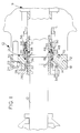
- Figure 1 is a cross-section of a split seal in accordance with the invention.
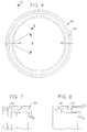
- Figure 2 is a rear view of a mating ring as used in the invention embodied in Fig. 1.
- Figure 3 is a cross-sectional view of the mating ring of Fig. 2.
- Figure 4 is a rear view of a seal ring as used in the invention embodied in Fig. 1.
- Figure 5 is a partial cross-sectional view of the seal ring of Figure 4 at Section V-V.
- Figure 6 is a rear view of the seal ring shell as used in the invention embodied in Fig. 1.
- Figure 7 is a partial cross section of the seal ring shell taken along lines VII-VII shown in Fig. 6.
- Figure 8 is a partial cross-section of the seal ring shell taken along lines VIII-VIII shown in Fig. 6.
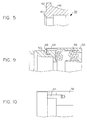
- Figure 9 is a partial cross-section of the cup and pin as used in the invention embodied in Fig. 1.
- Figure 10 is a partial cross-section of the cup at a pin hole.
- Figure 11 is a front view of a cup as used in the invention embodied in Fig. 1.
- Figure 12 is a front view of an "O" ring as used in the invention embodied in Fig. 1.
- a split seal 10 for sealing along a shaft 12 is in pumps.
- the seal fits in an existing seal cavity within pump housing 9.
- High pressure fluid in the pump exists along the shaft and to the radially outer side of the seal.
- Sleeve 11 and sleeve 13 surround the shaft.
- Sleeve 13 is installed first and abuts sleeve 11 which is threaded onto shaft 12 with threads 15 and secured from rotation by set screw 17.
- "O" ring 19 prevents leakage along the shaft.
- the split seal 10 comprises a stationary split mating ring 14.
- Mating ring 14 is preferably made of silicon carbide. As shown in Figs. 2, the mating ring is preferably split into two sections. The ring is split by first forming two grooves 16 having an angle ⁇ of 60° ⁇ 20° and then cracking the ring at the grooves. When assembled, mating ring 14 is squeezed together and attached by press-fit in gland 18, as shown in Fig. 1. Gland 18 is a removable portion of housing 9.
- Split "O"-ring 20 seals along the radially outer side of the mating ring and split "O"-ring 21 seals between the gland and the housing.
- the gland is solid and preferably made of stainless steel.
- the gland retains the mating ring so that it does not rotate, and the gland is held in place by a plurality of nuts 22 and bolts 24.
- means for selectively dislodging the mating ring is provided with set screw holes 36 in the gland so that set screws can be used to apply pressure to dislodge the mating ring.
- the assembly includes a packing gland 26 behind the mating ring.
- the packing gland may be either split or solid and further has an annular tongue 28 which fits into an annular groove 30 in the gland 18.
- Packing material 32 (preferably Ramie®) is placed around the shaft and the packing gland 26 is drawn toward the gland 18 by means of a plurality of cap screws 34. This causes the packing material to be compressed to seal along the shaft.
- the seal assembly also includes an annular rotary split seal ring 38.
- the split ring (best shown in Figs. 4 and 5) is preferably made of carbon.
- the seal ring is preferably split into two sections. The ring is split by first forming two grooves 40 having an angle ⁇ of 60° ⁇ 20° and then cracking the ring at the grooves.
- the seal ring has a front surface 42 which faces the mating ring. Protruding from the front surface is a sealing face 44 which in operation is in pressing engagement with the mating ring 14.
- the sealing faced is preferably lapped flat within 3 helium light bands.
- the seal face is preferably aligned as known in the art to affect balance of the seal.
- the split seal ring is compressed and held in place by engagement between an outer tapered surface 46 of the seal ring which tapers in decreasing diameter away from the sealing face and inner tapered surface 48 on seal ring retainer shell 50 for slidingly fitting over the outer tapered portion of the split seal ring.
- shell 50 is preferably a solid annular form made of stainless steel.
- an annular groove 52 is formed in the shell and a split "O" ring 54 (shown in Fig. 1) is located in the groove.
- An additional split "O" ring 55 is located between the rear surface of the seal ring (away from the sealing surface) and the rearward axially orthogonal wall 51 of shell 50.
- means for axially urging shell 50 toward the split seal ring includes springs 56 which press against an annular non-split cup 58.
- sixteen coil springs 56 are provided which rest in apertures or spring holes 60 in shell 50 and, as shown in Fig. 11, these springs also rest in the respective apertures or holes 62 in the bottom of cup 58.
- a key 59 fits into key hole 63 (shown in Fig. 11) and acts to prevent rotation of the cup relative to the shaft.
- cup 58 rotates with the shaft.
- Shims 61 are supplied to position the seal to the correct operating length. As shown in Fig.
- drive pins 64 are provided which pass from the cup 58 into drive pin holes 65 in the shell and serve to cause rotation of the cup 58, shell 50 and seal ring 38 with the shaft.
- two pins are provided which fit into pin holes 65 (shown in Figs. 6 and 11).
- the springs which are fitted into deep pockets, may act as a drive to cause the rotation of the shell.
- Means for limiting axial sliding are preferably provided with an extended annular sidewall with a cross-sectionally "L" shaped annular finger section 64 on cup 58. The finger section extends over the rear portion of the shell 50 and clips onto a split retainer ring 65 placed in annular groove 68 in the shell. The retainer ring allows the springs to compress but keeps the cup and shell from separating.
- the springs cause the two tapered portions and the split "O" ring to engage, which generates a high radial load that keeps the split halves together at high speeds.
- the axially load exerted by the springs 56 is transferred to the seal ring by taper 46 in a ratio of radial to axial forces determined by the angle of the taper. With a preferred angle of 15 °, the radial load is approximately four times the axially load.
- the springs have a 25.4 mm (one inch) free length and exert an axial load of between 24.5 N (5.5 lbs.) and 31.2 N (7 lbs.) when to compressed to 12.7 mm (one-half inch).
- the friction forces between the seal ring 38, split "O"-rings 54 and 55, and the shell 50 cause the seal ring to rotate with the shell 50, and therefore with the shaft.
- the volume of split "O"-ring 54 is selected so that it is greater than the volume of groove 52. This ensures that the axial and radial load of the taper will be transferred through the split "O"-ring. Since the load is transmitted through a rubber "O" ring, the force is distributed uniformly about the circumference of the split seal ring and leakage past the tapered diameter is eliminated. Furthermore, the load is always transmitted at the same axial location on the seal ring which insures that the seal rotation caused by the loads will be the same for all seals, and the seal ring deflection and stress can be easily be calculated for best seal ring operation.
- the split seal is preferably provided with cooling.
- circulation port 70 is provided to circulate water into, around and out of the area near the seal face.
- the circulation port may be attached to either the intake or the exhaust port of the pump. Circulation is thus created around the sealing area because of a pressure differential between the pressure of the water being sealed and the port on the pump.
- the water is either drawn from the pump along the shaft and out the circulation port, or pushed into the pump along the shaft from the circulation port. It does not matter whether the water flows into or out of the circulation port as long as circulation is created.
- two circulation ports 70 may be provided, one for flowing water into the seal area and one for flowing the water out.
- the circulation port 70 is threaded so that a plug 72 may be placed in it when the seal is not in use so as to prevent dirt from entering the seal.
- Uncoupling of pump 9 from the motor is necessary only during original installation of the seal. Uncoupling allows the non-split items (i.e., the cup 58, seal ring shell 50 and gland 18) to be installed over pump shaft 12.
- the sixteen coil springs 56 are placed into cup 58, and the split "O" rings 54 and 55 are greased and put into the seal ring shell 50 prior to installation of the seal ring shell on the shaft.
- the seal ring shell with split "O" rings is then installed on the shaft.
- the split seal ring 38 is placed into the seal ring shell until it touches split "O" ring 55.
- gland 18 containing split mating ring 14 is installed on shaft 12, and nuts 22 on bolts 24 are tightened.
- shaft packing material 32 is placed into split gland 26 and over shaft 12, and cap screws 34 are tightened.
- the water circulation tube is attached to circulation port 70.
- the seal can now be removed without uncoupling the pump from the motor.
- the split packing gland 26 and packing material 32 are removed along with gland cap screws 24. Set screws are then screwed into set screw holes 36 in gland 18 to disengage the mating ring 14 from gland 18.
- the gland is then lifted and secured as far away from the pump housing as possible in order to the allow maximum axial space to remove the seal parts.
- the split mating ring 14 and split seal ring 38 are removed.
- the split "O" rings 54 and 55, split seal ring 38 and the mating ring 14 can now be replaced and the seal re-assembled.
- the seal of this invention has a major advantage over ordinary mechanical pump seals in that the sealing faces and all of the split "O"-rings can be replaced without uncoupling the pump from the shaft. Furthermore, the seal is capable of operating at speeds of 1700 to 3500 rpm while leaking no more than 60 drops of water per minute.
Landscapes
- Engineering & Computer Science (AREA)
- General Engineering & Computer Science (AREA)
- Mechanical Engineering (AREA)
- Mechanical Sealing (AREA)
- Gasket Seals (AREA)
- Sealing Material Composition (AREA)
Claims (14)
- Joint fendu destiné à former un joint entre un carter (18) et un arbre (12) comprenant :une bague d'accouplement fendue fixe (14) fixée au carter (9),une bague d'étanchéité fendue rotative annulaire (38) comportant une face d'étanchéité venant en butée contre ladite bague d'accouplement et une surface extérieure tronconique qui se réduit en tronc de cône dans son diamètre décroissant en s'écartant de ladite face d'étanchéité,une coquille de bague d'étanchéité annulaire (50) comportant une partie tronconique intérieure conçue pour s'adapter de façon coulissante sur ladite partie tronconique extérieure de ladite bague d'étanchéité (38) qui est fixée de façon à tourner avec l'arbre (12),et un moyen (56) destiné à solliciter axialement ladite coquille (50) en direction de ladite bague d'étanchéité fendue rotative (38) et ladite bague d'accouplement fendue fixe (14), caractérisé par un moyen (54) destiné à transférer uniformément la force de sollicitation depuis ladite coquille (50) vers ladite bague d'étanchéité fendue rotative (38) en assurant une répartition uniforme de la force entre la coquille (50) et la bague (38) de façon à empêcher les fuites le long de ladite bague d'étanchéité fendue rotative, ledit moyen comprenant une gorge annulaire (52) formée dans ladite partie tronconique intérieure et un premier joint torique (54) adapté dans ladite gorge annulaire (52).
- Joint fendu selon la revendication 1, dans lequel ladite bague d'étanchéité fendue (38) comporte une première surface orientée vers ladite bague d'accouplement (14) et dans lequel ladite face d'étanchéité (44) s'étend sur au moins une partie de ladite première surface.
- Joint fendu selon la revendication 2, dans lequel ladite bague d'étanchéité fendue (38) comporte une seconde surface axialement éloignée de ladite première surface, ladite coquille de bague d'étanchéité présente une surface axialement orthogonale en regard de ladite seconde surface, et ladite bague d'étanchéité fendue (38) comprend en outre un second joint torique (55) entre ladite seconde surface et ladite surface axialement orthogonale.
- Joint fendu selon la revendication 1, comprenant en outre un troisième joint torique (20) en contact sous pression avec une surface externe de ladite bague d'accouplement (14).
- Joint fendu selon la revendication 1, dans lequel ledit premier joint torique (54) est fendu et est d'un diamètre plus important que le diamètre de ladite gorge annulaire (52).
- Joint fendu selon la revendication 1, dans lequel le moyen destiné à la sollicitation comprend au moins un ressort (56).
- Joint fendu selon la revendication 6, dans lequel ledit moyen destiné à la sollicitation comprend :une cuvette annulaire comportant un fond (58) et une paroi latérale extérieure axialement allongée (64), ladite paroi latérale extérieure axialement allongée étant conçue pour recevoir de façon coulissante ladite coquille de bague d'étanchéité (50), etau moins un ressort (56) positionné entre le fond (58) de ladite coupelle et ladite coquille de bague d'étanchéité (50).
- Joint fendu selon la revendication 7, comprenant en outre au moins une ouverture (62) formée dans ledit fond de ladite coupelle et au moins une ouverture (60) formée dans ladite coquille en regard de ladite coupelle, ladite ouverture (62) de ladite coupelle et ladite ouverture (60) de ladite coquille (50) étant alignées et supportant ledit ressort (56).
- Joint fendu selon la revendication 7, comprenant en outre un moyen (66, 68) destiné à limiter le glissement axial de ladite coquille de bague d'étanchéité relativement à ladite coupelle annulaire.
- Joint fendu selon la revendication 9, dans lequel ledit moyen de limitation comprend une gorge annulaire (68) formée dans ladite coquille (50), une bague de retenue fendue (66) adaptée à l'intérieur de ladite gorge annulaire (68) et s'étendant radialement au-delà de celle-ci, et un doigt axialement allongé en forme de "L" annulaire formé sur ladite coupelle, qui s'étend au-dessus de ladite bague de retenue.
- Joint fendu selon la revendication 7, comprenant en outre des broches d'entraínement (64) passant depuis ladite coupelle jusque dans ladite coquille.
- Joint fendu selon la revendication 1, comprenant en outre un presse-étoupe annulaire (18) fixé de façon amovible audit carter (9), ladite bague d'accouplement fixe (14) étant adaptée en ajustement serré à l'intérieur dudit presse-étoupe (18).
- Joint fendu selon la revendication 12, comprenant en outre un moyen (20) destiné à décaler sélectivement ladite bague d'accouplement fixe fendue (14) par rapport audit presse-étoupe (18).
- Joint fendu selon la revendication 13, dans lequel ledit moyen de décalage est un troisième joint torique fendu (20), permettant ainsi le remplacement facile de ladite bague d'accouplement (14), de la bague d'étanchéité et du joint torique.
Applications Claiming Priority (2)
| Application Number | Priority Date | Filing Date | Title |
|---|---|---|---|
| US477417 | 1990-02-09 | ||
| US07/477,417 US5020809A (en) | 1990-02-09 | 1990-02-09 | High-speed easy-maintenance split seal |
Publications (3)
| Publication Number | Publication Date |
|---|---|
| EP0441405A2 EP0441405A2 (fr) | 1991-08-14 |
| EP0441405A3 EP0441405A3 (en) | 1993-06-30 |
| EP0441405B1 true EP0441405B1 (fr) | 1998-12-02 |
Family
ID=23895838
Family Applications (1)
| Application Number | Title | Priority Date | Filing Date |
|---|---|---|---|
| EP91101810A Expired - Lifetime EP0441405B1 (fr) | 1990-02-09 | 1991-02-08 | Joint fendu à grande vitesse d'entretien facile |
Country Status (4)
| Country | Link |
|---|---|
| US (1) | US5020809A (fr) |
| EP (1) | EP0441405B1 (fr) |
| AT (1) | ATE174109T1 (fr) |
| DE (1) | DE69130543T2 (fr) |
Families Citing this family (34)
| Publication number | Priority date | Publication date | Assignee | Title |
|---|---|---|---|---|
| US5192085A (en) * | 1990-12-17 | 1993-03-09 | Mconie Robert | Rubber drive system mechanical seal |
| GB9512267D0 (en) * | 1995-06-16 | 1995-08-16 | Management Consultancy Service | Improved split seal |
| GB2316721B (en) * | 1996-09-02 | 2000-11-22 | Aes Eng Ltd | Mechanical seal |
| US6171070B1 (en) * | 1997-05-09 | 2001-01-09 | Hakusu Tech Co., Ltd. | High-pressure reciprocating pumps |
| WO1998058199A1 (fr) * | 1997-06-16 | 1998-12-23 | Garlock Inc. | Element d'etancheite fendu |
| US5913521A (en) * | 1997-08-29 | 1999-06-22 | John Crane Sealol Inc. | Rotating seal ring component kit for a mechanical split seal |
| US6131912A (en) * | 1997-12-17 | 2000-10-17 | A.W. Chesterton Company | Split mechanical face seal |
| US6059293A (en) * | 1997-12-17 | 2000-05-09 | A.W. Chesterton Company | Split mechanical face seal with seal face fluid introducing structure |
| US6076830A (en) * | 1997-12-17 | 2000-06-20 | A.W. Chesterton Company | Dual non-contacting mechanical face seal having concentric seal faces |
| SE515508C2 (sv) * | 1998-10-08 | 2001-08-20 | Goeran Anderberg | Tätning vid genomföring av en roterande axel genom en vägg |
| US20040201176A1 (en) * | 1999-07-27 | 2004-10-14 | Bjornson Carl C. | Mechanical split seal |
| CA2382996C (fr) | 1999-07-27 | 2008-12-02 | Northeast Equipment, Inc. D/B/A Delta Mechanical Seals | Joint fendu mecanique |
| US6550779B2 (en) | 1999-07-27 | 2003-04-22 | Northeast Equipment, Inc. | Mechanical split seal |
| US6485023B2 (en) | 2000-05-04 | 2002-11-26 | Flowserve Management Company | Split mechanical face seal |
| US6412784B1 (en) | 2000-05-26 | 2002-07-02 | The United States Of America As Represented By The Secretary Of The Navy | Split face mechanical seal system |
| US9416887B2 (en) | 2000-07-18 | 2016-08-16 | George H Blume | Low turbulence valve |
| US8915722B1 (en) | 2009-02-23 | 2014-12-23 | George H. Blume | Integrated fluid end |
| US8147227B1 (en) | 2000-07-18 | 2012-04-03 | Blume George H | Valve guide and spring retainer assemblies |
| US6544012B1 (en) * | 2000-07-18 | 2003-04-08 | George H. Blume | High pressure plunger pump housing and packing |
| US6485024B1 (en) * | 2000-09-06 | 2002-11-26 | Utex Industries, Inc. | Split mechanical face seal |
| DE10155653C2 (de) * | 2001-11-13 | 2003-10-30 | Federal Mogul Friedberg Gmbh | Gleitringdichtung mit geteilten Gleitringen |
| DE102004004938B4 (de) * | 2004-01-31 | 2007-11-29 | Ab Skf | Dichtungsanordnung |
| FI117300B (fi) * | 2005-04-29 | 2006-08-31 | Sulzer Pumpen Ag | Virtauskone, sen liukurengastiiviste, liukurengastiivisteen runkokappale ja menetelmä liukurengastiivisteen kiinnittämiseksi virtauskoneeseen |
| WO2007058306A1 (fr) * | 2005-11-17 | 2007-05-24 | Eagle Industry Co., Ltd. | Dispositif d'etancheite mecanique |
| USD616966S1 (en) * | 2009-02-11 | 2010-06-01 | Kmt Waterjet Systems Inc. | Outer follower element for a high pressure seal |
| USD631142S1 (en) * | 2009-02-11 | 2011-01-18 | Kmt Waterjet Systems Inc. | Inner packing element for a high pressure seal |
| US9435454B2 (en) | 2009-02-23 | 2016-09-06 | George H Blume | Fluid end with carbide valve seat and adhesive dampening interface |
| US9377019B1 (en) | 2012-05-07 | 2016-06-28 | George H Blume | Opposing offset fluid end bores |
| US10458725B2 (en) | 2013-03-15 | 2019-10-29 | Dana Canada Corporation | Heat exchanger with jointed frame |
| DE102016201538B4 (de) * | 2016-02-02 | 2017-08-31 | Eagleburgmann Germany Gmbh & Co. Kg | Gleitringdichtungsanordnung mit vereinfachtem Aufbau |
| GB2559136B (en) * | 2017-01-25 | 2020-04-15 | Edwards Ltd | Vacuum pump with biased stator seals and method of manufacture thereof |
| US11015715B2 (en) | 2018-03-22 | 2021-05-25 | Raytheon Technologies Corporation | Ramped spacer ring seal |
| US11708909B2 (en) * | 2018-04-27 | 2023-07-25 | Hamilton Sundstrand Corporation | Carbon seal |
| GB2588753B (en) * | 2019-10-21 | 2021-11-03 | Rubberatkins Ltd | Seal with back-up ring |
Family Cites Families (7)
| Publication number | Priority date | Publication date | Assignee | Title |
|---|---|---|---|---|
| US1009303A (en) * | 1909-01-20 | 1911-11-21 | Ingersoll Rand Co | Drill-steel chuck for stoneworking-machines. |
| GB933389A (en) * | 1961-07-06 | 1963-08-08 | Flexibox Ltd | Improvements relating to mechanical seals |
| US3625524A (en) * | 1970-08-13 | 1971-12-07 | Amf Inc | Rotatable seal |
| US3675933A (en) * | 1970-09-03 | 1972-07-11 | Crane Packing Co | Seal with installed space parts |
| US4239240A (en) * | 1979-08-07 | 1980-12-16 | Crane Packing Limited | Rotary mechanical face seals |
| US4410188A (en) * | 1982-11-17 | 1983-10-18 | Copes John C | Slurry pump double mechanical split face seal |
| US4792146A (en) * | 1987-02-17 | 1988-12-20 | University Of New Mexico | Radially compliant - zero net thermal radial taper mechanical face seal |
-
1990
- 1990-02-09 US US07/477,417 patent/US5020809A/en not_active Expired - Lifetime
-
1991
- 1991-02-08 EP EP91101810A patent/EP0441405B1/fr not_active Expired - Lifetime
- 1991-02-08 AT AT91101810T patent/ATE174109T1/de not_active IP Right Cessation
- 1991-02-08 DE DE69130543T patent/DE69130543T2/de not_active Expired - Fee Related
Also Published As
| Publication number | Publication date |
|---|---|
| DE69130543D1 (de) | 1999-01-14 |
| ATE174109T1 (de) | 1998-12-15 |
| DE69130543T2 (de) | 1999-04-29 |
| EP0441405A3 (en) | 1993-06-30 |
| EP0441405A2 (fr) | 1991-08-14 |
| US5020809A (en) | 1991-06-04 |
Similar Documents
| Publication | Publication Date | Title |
|---|---|---|
| EP0441405B1 (fr) | Joint fendu à grande vitesse d'entretien facile | |
| US4511149A (en) | Mechanical seal with cylindrical balance sleeve | |
| EP0731301B1 (fr) | Dispositif d'étanchéité | |
| US6939053B2 (en) | System and method for mounting a shaft within a hollow member | |
| US5211535A (en) | Labyrinth seals for gas turbine engine | |
| US4586719A (en) | Mechanical seal | |
| US5954341A (en) | Bellows seal with drive collar for reverse pressure capability | |
| CA1141405A (fr) | Garniture hydrostatique pour pompes centrifuges | |
| EP0446531A1 (fr) | Joint mécanique | |
| US4669760A (en) | Swivel fitting arrangement for use in a pressurized fluid line | |
| US6186510B1 (en) | Mechanical contact bearing seal | |
| US4752077A (en) | Sliding ring seal | |
| AU7370696A (en) | Bearing housing seal | |
| WO1994005936A1 (fr) | Enceinte pour materiaux de revetement de garniture mecanique d'etancheite friables | |
| US6568686B2 (en) | Mechanical rotary seal | |
| US4183541A (en) | Mechanical seal assembly | |
| US5042824A (en) | Balanced shrink fit seal ring assembly | |
| EP0226845B1 (fr) | Garniture d'étanchéité en une seule pièce | |
| US4759554A (en) | Mechanical face seals | |
| EP0211051A1 (fr) | Joint d'etancheite mecanique. | |
| EP0266664A2 (fr) | Disposition d'un boîtier pour presse-étoupes | |
| US4605235A (en) | High thrust capacity shaft seal assembly for fuel pumps | |
| CA1244073A (fr) | Palier de butee avec dispositif d'etancheite | |
| US4795169A (en) | Radially stable mechanical face seals | |
| GB2143911A (en) | Face seals |
Legal Events
| Date | Code | Title | Description |
|---|---|---|---|
| PUAI | Public reference made under article 153(3) epc to a published international application that has entered the european phase |
Free format text: ORIGINAL CODE: 0009012 |
|
| AK | Designated contracting states |
Kind code of ref document: A2 Designated state(s): AT BE CH DE DK ES FR GB GR IT LI LU NL SE |
|
| PUAL | Search report despatched |
Free format text: ORIGINAL CODE: 0009013 |
|
| AK | Designated contracting states |
Kind code of ref document: A3 Designated state(s): AT BE CH DE DK ES FR GB GR IT LI LU NL SE |
|
| 17P | Request for examination filed |
Effective date: 19931207 |
|
| 17Q | First examination report despatched |
Effective date: 19960313 |
|
| GRAG | Despatch of communication of intention to grant |
Free format text: ORIGINAL CODE: EPIDOS AGRA |
|
| GRAG | Despatch of communication of intention to grant |
Free format text: ORIGINAL CODE: EPIDOS AGRA |
|
| GRAH | Despatch of communication of intention to grant a patent |
Free format text: ORIGINAL CODE: EPIDOS IGRA |
|
| GRAH | Despatch of communication of intention to grant a patent |
Free format text: ORIGINAL CODE: EPIDOS IGRA |
|
| RAP1 | Party data changed (applicant data changed or rights of an application transferred) |
Owner name: JOHN CRANE INC. |
|
| GRAA | (expected) grant |
Free format text: ORIGINAL CODE: 0009210 |
|
| AK | Designated contracting states |
Kind code of ref document: B1 Designated state(s): AT BE CH DE DK ES FR GB GR IT LI LU NL SE |
|
| PG25 | Lapsed in a contracting state [announced via postgrant information from national office to epo] |
Ref country code: IT Free format text: LAPSE BECAUSE OF FAILURE TO SUBMIT A TRANSLATION OF THE DESCRIPTION OR TO PAY THE FEE WITHIN THE PRESCRIBED TIME-LIMIT;WARNING: LAPSES OF ITALIAN PATENTS WITH EFFECTIVE DATE BEFORE 2007 MAY HAVE OCCURRED AT ANY TIME BEFORE 2007. THE CORRECT EFFECTIVE DATE MAY BE DIFFERENT FROM THE ONE RECORDED. Effective date: 19981202 Ref country code: CH Free format text: LAPSE BECAUSE OF FAILURE TO SUBMIT A TRANSLATION OF THE DESCRIPTION OR TO PAY THE FEE WITHIN THE PRESCRIBED TIME-LIMIT Effective date: 19981202 Ref country code: BE Free format text: LAPSE BECAUSE OF FAILURE TO SUBMIT A TRANSLATION OF THE DESCRIPTION OR TO PAY THE FEE WITHIN THE PRESCRIBED TIME-LIMIT Effective date: 19981202 Ref country code: ES Free format text: THE PATENT HAS BEEN ANNULLED BY A DECISION OF A NATIONAL AUTHORITY Effective date: 19981202 Ref country code: LI Free format text: LAPSE BECAUSE OF FAILURE TO SUBMIT A TRANSLATION OF THE DESCRIPTION OR TO PAY THE FEE WITHIN THE PRESCRIBED TIME-LIMIT Effective date: 19981202 Ref country code: AT Free format text: LAPSE BECAUSE OF FAILURE TO SUBMIT A TRANSLATION OF THE DESCRIPTION OR TO PAY THE FEE WITHIN THE PRESCRIBED TIME-LIMIT Effective date: 19981202 |
|
| REF | Corresponds to: |
Ref document number: 174109 Country of ref document: AT Date of ref document: 19981215 Kind code of ref document: T |
|
| REG | Reference to a national code |
Ref country code: CH Ref legal event code: EP |
|
| REF | Corresponds to: |
Ref document number: 69130543 Country of ref document: DE Date of ref document: 19990114 |
|
| PG25 | Lapsed in a contracting state [announced via postgrant information from national office to epo] |
Ref country code: LU Free format text: LAPSE BECAUSE OF NON-PAYMENT OF DUE FEES Effective date: 19990208 |
|
| ET | Fr: translation filed | ||
| RAP2 | Party data changed (patent owner data changed or rights of a patent transferred) |
Owner name: JOHN CRANE UK LIMITED |
|
| PG25 | Lapsed in a contracting state [announced via postgrant information from national office to epo] |
Ref country code: DK Free format text: LAPSE BECAUSE OF FAILURE TO SUBMIT A TRANSLATION OF THE DESCRIPTION OR TO PAY THE FEE WITHIN THE PRESCRIBED TIME-LIMIT Effective date: 19990302 Ref country code: SE Free format text: LAPSE BECAUSE OF FAILURE TO SUBMIT A TRANSLATION OF THE DESCRIPTION OR TO PAY THE FEE WITHIN THE PRESCRIBED TIME-LIMIT Effective date: 19990302 |
|
| REG | Reference to a national code |
Ref country code: FR Ref legal event code: TP |
|
| NLT2 | Nl: modifications (of names), taken from the european patent patent bulletin |
Owner name: JOHN CRANE UK LIMITED |
|
| REG | Reference to a national code |
Ref country code: CH Ref legal event code: PL |
|
| NLXE | Nl: other communications concerning ep-patents (part 3 heading xe) |
Free format text: PAT. BUL. 04/99 PAGE 503: CORR.: JOHN CRANE UK LIMITED |
|
| PLBE | No opposition filed within time limit |
Free format text: ORIGINAL CODE: 0009261 |
|
| STAA | Information on the status of an ep patent application or granted ep patent |
Free format text: STATUS: NO OPPOSITION FILED WITHIN TIME LIMIT |
|
| 26N | No opposition filed | ||
| REG | Reference to a national code |
Ref country code: GB Ref legal event code: IF02 |
|
| REG | Reference to a national code |
Ref country code: GB Ref legal event code: 732E |
|
| PGFP | Annual fee paid to national office [announced via postgrant information from national office to epo] |
Ref country code: DE Payment date: 20040116 Year of fee payment: 14 Ref country code: GR Payment date: 20040116 Year of fee payment: 14 |
|
| NLS | Nl: assignments of ep-patents |
Owner name: DEEP SEA SEALS LIMITED |
|
| REG | Reference to a national code |
Ref country code: FR Ref legal event code: TP |
|
| PG25 | Lapsed in a contracting state [announced via postgrant information from national office to epo] |
Ref country code: DE Free format text: LAPSE BECAUSE OF NON-PAYMENT OF DUE FEES Effective date: 20050901 |
|
| PG25 | Lapsed in a contracting state [announced via postgrant information from national office to epo] |
Ref country code: GR Free format text: LAPSE BECAUSE OF NON-PAYMENT OF DUE FEES Effective date: 20050905 |
|
| PGFP | Annual fee paid to national office [announced via postgrant information from national office to epo] |
Ref country code: NL Payment date: 20070115 Year of fee payment: 17 |
|
| PGFP | Annual fee paid to national office [announced via postgrant information from national office to epo] |
Ref country code: FR Payment date: 20070111 Year of fee payment: 17 |
|
| NLV4 | Nl: lapsed or anulled due to non-payment of the annual fee |
Effective date: 20080901 |
|
| PG25 | Lapsed in a contracting state [announced via postgrant information from national office to epo] |
Ref country code: NL Free format text: LAPSE BECAUSE OF NON-PAYMENT OF DUE FEES Effective date: 20080901 |
|
| REG | Reference to a national code |
Ref country code: FR Ref legal event code: ST Effective date: 20081031 |
|
| PG25 | Lapsed in a contracting state [announced via postgrant information from national office to epo] |
Ref country code: FR Free format text: LAPSE BECAUSE OF NON-PAYMENT OF DUE FEES Effective date: 20080229 |
|
| PGFP | Annual fee paid to national office [announced via postgrant information from national office to epo] |
Ref country code: GB Payment date: 20090714 Year of fee payment: 19 |
|
| GBPC | Gb: european patent ceased through non-payment of renewal fee |
Effective date: 20100208 |
|
| PG25 | Lapsed in a contracting state [announced via postgrant information from national office to epo] |
Ref country code: GB Free format text: LAPSE BECAUSE OF NON-PAYMENT OF DUE FEES Effective date: 20100208 |
|
| P01 | Opt-out of the competence of the unified patent court (upc) registered |
Effective date: 20230522 |