EP0441415A2 - Innenwand-Bearbeitungsgerät - Google Patents
Innenwand-Bearbeitungsgerät Download PDFInfo
- Publication number
- EP0441415A2 EP0441415A2 EP91107660A EP91107660A EP0441415A2 EP 0441415 A2 EP0441415 A2 EP 0441415A2 EP 91107660 A EP91107660 A EP 91107660A EP 91107660 A EP91107660 A EP 91107660A EP 0441415 A2 EP0441415 A2 EP 0441415A2
- Authority
- EP
- European Patent Office
- Prior art keywords
- cup
- shaped piston
- gear
- processing apparatus
- piston
- Prior art date
- Legal status (The legal status is an assumption and is not a legal conclusion. Google has not performed a legal analysis and makes no representation as to the accuracy of the status listed.)
- Granted
Links
Images


Classifications
-
- B—PERFORMING OPERATIONS; TRANSPORTING
- B08—CLEANING
- B08B—CLEANING IN GENERAL; PREVENTION OF FOULING IN GENERAL
- B08B9/00—Cleaning hollow articles by methods or apparatus specially adapted thereto
- B08B9/02—Cleaning pipes or tubes or systems of pipes or tubes
-
- F—MECHANICAL ENGINEERING; LIGHTING; HEATING; WEAPONS; BLASTING
- F16—ENGINEERING ELEMENTS AND UNITS; GENERAL MEASURES FOR PRODUCING AND MAINTAINING EFFECTIVE FUNCTIONING OF MACHINES OR INSTALLATIONS; THERMAL INSULATION IN GENERAL
- F16L—PIPES; JOINTS OR FITTINGS FOR PIPES; SUPPORTS FOR PIPES, CABLES OR PROTECTIVE TUBING; MEANS FOR THERMAL INSULATION IN GENERAL
- F16L55/00—Devices or appurtenances for use in, or in connection with, pipes or pipe systems
- F16L55/26—Pigs or moles, i.e. devices movable in a pipe or conduit with or without self-contained propulsion means
-
- B—PERFORMING OPERATIONS; TRANSPORTING
- B08—CLEANING
- B08B—CLEANING IN GENERAL; PREVENTION OF FOULING IN GENERAL
- B08B9/00—Cleaning hollow articles by methods or apparatus specially adapted thereto
- B08B9/02—Cleaning pipes or tubes or systems of pipes or tubes
- B08B9/027—Cleaning the internal surfaces; Removal of blockages
- B08B9/04—Cleaning the internal surfaces; Removal of blockages using cleaning devices introduced into and moved along the pipes
- B08B9/043—Cleaning the internal surfaces; Removal of blockages using cleaning devices introduced into and moved along the pipes moved by externally powered mechanical linkage, e.g. pushed or drawn through the pipes
- B08B9/047—Cleaning the internal surfaces; Removal of blockages using cleaning devices introduced into and moved along the pipes moved by externally powered mechanical linkage, e.g. pushed or drawn through the pipes the cleaning devices having internal motors, e.g. turbines for powering cleaning tools
-
- E—FIXED CONSTRUCTIONS
- E03—WATER SUPPLY; SEWERAGE
- E03F—SEWERS; CESSPOOLS
- E03F3/00—Sewer pipe-line systems
- E03F3/06—Methods of, or installations for, laying sewer pipes
-
- F—MECHANICAL ENGINEERING; LIGHTING; HEATING; WEAPONS; BLASTING
- F16—ENGINEERING ELEMENTS AND UNITS; GENERAL MEASURES FOR PRODUCING AND MAINTAINING EFFECTIVE FUNCTIONING OF MACHINES OR INSTALLATIONS; THERMAL INSULATION IN GENERAL
- F16L—PIPES; JOINTS OR FITTINGS FOR PIPES; SUPPORTS FOR PIPES, CABLES OR PROTECTIVE TUBING; MEANS FOR THERMAL INSULATION IN GENERAL
- F16L55/00—Devices or appurtenances for use in, or in connection with, pipes or pipe systems
- F16L55/18—Appliances for use in repairing pipes
-
- Y—GENERAL TAGGING OF NEW TECHNOLOGICAL DEVELOPMENTS; GENERAL TAGGING OF CROSS-SECTIONAL TECHNOLOGIES SPANNING OVER SEVERAL SECTIONS OF THE IPC; TECHNICAL SUBJECTS COVERED BY FORMER USPC CROSS-REFERENCE ART COLLECTIONS [XRACs] AND DIGESTS
- Y10—TECHNICAL SUBJECTS COVERED BY FORMER USPC
- Y10T—TECHNICAL SUBJECTS COVERED BY FORMER US CLASSIFICATION
- Y10T409/00—Gear cutting, milling, or planing
- Y10T409/30—Milling
- Y10T409/304424—Means for internal milling
-
- Y—GENERAL TAGGING OF NEW TECHNOLOGICAL DEVELOPMENTS; GENERAL TAGGING OF CROSS-SECTIONAL TECHNOLOGIES SPANNING OVER SEVERAL SECTIONS OF THE IPC; TECHNICAL SUBJECTS COVERED BY FORMER USPC CROSS-REFERENCE ART COLLECTIONS [XRACs] AND DIGESTS
- Y10—TECHNICAL SUBJECTS COVERED BY FORMER USPC
- Y10T—TECHNICAL SUBJECTS COVERED BY FORMER US CLASSIFICATION
- Y10T74/00—Machine element or mechanism
- Y10T74/18—Mechanical movements
- Y10T74/18568—Reciprocating or oscillating to or from alternating rotary
- Y10T74/18576—Reciprocating or oscillating to or from alternating rotary including screw and nut
- Y10T74/18688—Limit stop
Definitions
- the present invention relates to an inside processing apparatis for performing operations of cleaning, grinding, cutting and the like an inside of piping of a water supply pipe and a sewerage pipe laid under the ground, a gas pipe, a wire pipe and the like or an inside of tunnel and the like, and further an inside of steel pipe, a cylindrical face formed in steel ingot and the like.
- a concrete pipe, a steel pipe, an earthen pipe and the like having various diameter are laid under the ground as a water supply pipe and a sewerage pipe , a gas pipe, a wire pipe in the ground.
- a steel pipe pile, a steel pipe-sheet pile and the like are used in the job site of civil engineering works.
- the construction works including maintenance, repair, improvement or withdrawal and the like are performed in regard to the above-mentioned various pipes. Ay this time, it becomes necessary that the processing meeting the purpose of respective construction works in the inside of pipe is given, and therefore various pipe interior working machines meeting the purpose of construction works are provided.
- the working machine which is provided in order to perform the works as mentioned above is the so-called single capacity machine in which functions thereof are fixed, and said machine is construcred in such a manner that the tools including wire brush, milling cutter, end mill and the like are moved in the radial direction of pipeline by hydraulic cylinder and the like meeting the objective working, and said tools are rotated in the circumferential direction on an axial center of the working machine.
- a principal purpose of the present invention is to provided an inside processing apparatus by which plural works can be performed in regard to an inside of pipe.
- Another purpose is to provide an inside processing apparatus in which a quantity of movement of the tool in a radial direction of pipelinecan be set accurately.
- the inside processing apparatus in accordance with the present invention is comprised of a working head having the working member (tool) for performing a fixed work on the cylindrical wall surface processing, a driving mechanism for moving said working member in the circumferential direction of the cylindrical wall and a cutting controlling mechanism for moving said working head in the radial direction of cylindrical wall by said driving mechanism while controlling the amount of movement of said working head.
- the working head is comprised of a circular cam which has a center at a fixed distance from an axial center of the inside processing apparatus and which is rotated on the axial center of the inside processing apparatus and a head cover which has a link mechanism and engages with a cam surface of said circular cam so as to be rotatable on the center of the said circular cam and supports rotatably an axis on which the working member is mounted
- the driving mechanism is comprised of a sun gear, a first planet gear which engages with said sun gear and is connected with the circular cam forming the working head, a second planet gear which engages with said sun gear and is connected to the head cover consisting the working head through a link mechanism
- the cutting controlling mechanism is comprised of an internal gear which is rotatable and engages with the second planet gear and a driving means for driving said internal gear
- the driving means is comprised of a piston performing a straight reciprocation in the casing, an axis which engages with said piston and convert
- the working member including most suitable wire-brush, grinder, milling cutter and the like meeting the purpose of works is rotated on the axial line of said working member, said working member is movable along the inside of pipe, and it is possible that a fixed working is performed on the inner wall by this movement.
- a circular cam connected with the first planet gear rotates at a fixed velocity in the fixed direction on an axial center of the inside processing apparatus
- a link mechanism includes the head cover, and the rotating velocity which is identical with the rotating velocity of the circular cam is transmitted through an arm connected with the second planet gear and a link plate. Accordingly, without a sliding between the circular cam and the head cover, the rotation of the head cover is performed at the same velocity in the same direction on the axial center of the inside processing apparatus. Therefore, it is possible that the axis which is supported by the head cover and to which the working member installed is rotated in the circumferential direction on an axial center of the inside processing apparatus.
- the circular cam connected with the first planet gear rotates at a fixed velocity in a fixed direction on an axial center of the inside processing apparatus while a revolution velocity of the second planet gear is transmitted to the head cover through an arm and a like plate.
- a crossing angle between an arm and a link plate changes depending on the revolving velocity difference between the first planet gear and the second planet gear while the head cover is rotated on the center of circular cam. Therefore, a center of the circular cam is displaced on a circumference of which center is in the axial center of the inside processing apparatus, while positions of the head cover change as being limited by a central position of the circular cam and a crossing angle between an arm and a link plate.
- the moving direction of the head cover may be restricted by the link mechanism, it is possible that the working member is moved in the radial direction on an axial center of the inside processing apparatus.
- the first planet gear maintains a state in which the revolution is stopped and the second planet gear only revolves round the sun gear.
- the head cover is rotates while the circular cam is stopped. Therefore, the rotation is transmitted to the head cover through an arm and a link plate.
- a position of the rotating center ( a center of the circular cam ) of the head cover is fixed, a crossing angle between an arm and a link plate changes by the rotating force transmitted through an arm, and simultaneously the head cover is rotated on the center of the circular cam.
- the working member moves in the radial direction of the inside processing apparatus.
- a movement to the radial direction of the working member is not a straight movement, but becomes a spiral movement which is composed of a rotating motion on an axial center of the inside processing apparatus and a straight movement regulated by a link mechanism.
- a distance between an axial center of the inside processing apparatus ans a working member attached to the processing head can be set. Namely, an initial radius of the working member according to a diameter of pipe can be set. Also, in case that the internal gear can be detached or tached from or to the inner wall of pipe according to said working member at the driving time of the sun gear, or a depth of cutting of the inner wall of pipe in accordance with said working member can be set while the working member is moved in the direction of the circumference of a circle.
- an approaching distance or a cutting depth and an approaching velocity or a cutting velocity in regard to the inner wall of pipe in accordance with the working member can be set to a desirable value.
- Fig.1 is a side explanatory view of the inside processing apparatus in the present invention.
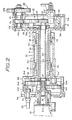
- Fig.2 is a sectional explanatory view of the inside processing apparatus in the presentinvention.
- Fig.3 is an explanatory view of transmitting system of a driving force in the present invention.
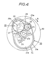
- Fig.4 is an explanatory view of construction of the working head in the present invention.
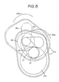
- Fig.5 is an explanatory view of operation of the working head in the present invention.
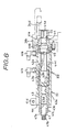
- Fig.6 is a sectional explanatory view of driving means of the inner teeth gear in the present invention.
- an inside processing apparatus is shown as an apparatus for cutting a groove in a fixed position of the inside of pipeline 60 made of a concrete pipe.
- a truck 10 which is in contact with an inner wall of the pipeline 60 and is drawn by cable 70a and 70b, is arranged in the pipeline 60.
- the truck 10 is formed in the front (cable 70b side in the drawing and so forth with a bracket), and in the rear (cable 70a side in the drawing and so forth with a bracket 12).
- a working head 20 which is furnished with a milling cutter as the working member 20a, a driving mechanism 30, a cutting controlling mechanism 40 are mounted to the bracket 11 movably in the front and rear directions.
- a feed mechanism 50 is comprised of a hydraulic cylinder, and a rod is secured to an expanding diameter portion 31a of the driving mechanism 30 where said cylinder is secured to the bracket 12. Therefore, the supply of hydraulic oil to the feed mechanism 50, makes possible that above-mentioned respective mechanism 20 to 40 can be moved in the front and rear directions.
- a bracket 11 which is formed on the truck 10 is provided with plural outriggers 80.
- These outriggers 80 are comprised of an hydraulic cylinder and are arranged at three places with a distance of 120 degrees for example round the outer circumference of the bracket 11. Therefore, the operation of the outriggers 80 by supplying the hydraulic oil to the outriggers 80 simultaneously, when the inside processing apparatus is secured to the pipeline 60, while that an axial center of the said inside processing apparatus can be coaxial with an axial center of the pipeline 60.
- the truck 10 is constructed so as to be able to be drawn by the cables 70a and 70b, however said truck can be also constructed as a self-propelled truck by that said truck 10 is provided with a wheel and mounted with the driving motor in the truck 10.
- the driving mechanism 30 is comprised of a case body 31 which is inserted in the bracket 11 of the truck 10, a motor 32 including an hydraulic motor, an induction motor and the like which becomes the source of power, said source of power secured being mounted on the end of the rear side of this case body 31, a shaft 33 which is mounted rotatably on the case body 11 and driven by motor 32, and a differential gear mechanism 34 which is disposed within an expanding diameter portion 31a formed at the end of rear side of the case body 31.
- the shaft 33 is disposed to be coaxial center of the inside processing apparatus.
- Said shaft 33 is connected with an output axis 32a of the motor 32, through a sleeve coupling 35.
- a gear portion 33a is formed in the backward end portion of the shaft 33, and this gear 33a is constituted as the sun gear 33a in the differential gear mechanism 34.
- the under-mentioned working head 20 is arranged on the front side of the shaft 33.
- the differential gear mechnism 34 is comprised of two planet gear mechanism.
- the first planet mechanism is comprised of an internal gear 34a which is secured in the expanding diameter portion 31a, a first planet gear 34b which engages both with the sun gear33a and with this internal gear 34a, and an outside sleeve 34c on which an axis 34c is secured, said axis 34c supports this first planet gear 34b rotatably.
- the second planet gear mechanism is comprised of an internal gear 34d which is disposed rotatably within a expanding diameter portion 31a, a second planet gear 34e which engages both with the sun gear 33a which engages with this internal gear 34d and an inside sleeve 34f on which an axis 34f is secured said axis 34f supporting this second planet gear 34e rotatably.
- the above-mentioned internal gear 34a and 34d are comprised of the same module with the same member of teeth, respectively and planet gears 34b, and 34e is also comprised of the same module with the same number of teeth respectively.
- a gear 45 attached to the driving axis 44 of the driving means which constitutes the cutting controlling mechanism 40 is engaged with the internal gear 34d constituting the second planet mechanism.
- the outside sleeve 34c is disposed on the same axis as an axis of the shaft 33, and is supported rotatably in the case body 31 through the bearing 36.
- the inside sleeve 34f is arranged between the outside sleeve 34c and the shaft 33, and is supported rotatably by the bearing 37 which is mounted on the shaft 33. Namely, the outside sleeve 34c is inserted in the case body 31 through the bearing 36, the inside sleeve 34f is inserted in this outside sleeve 34c, and further the shaft 33 is inserted in the inside sleeve 34f, so that each sleeve 34c, 34f and the shaft 33 can be rotated independently, respectively.
- the working head 20 is comprised of a case 21 and a gear mechanism 22 which is mounted in this case 21.
- the case 21 is comprised of a circular cam 21b which is secured on the outside sleeve 34c constituting the first planet gear mechanism, an arm 27 which is secured on the inside sleeve 34f and insereted by the circular cam 21b, and a head cover 21a which is connected with the second planet gear mechanism through a link mechanism comprised of a link plate 28.
- the bearing portion 21a' for supporting an axis 24 on which a working member 20a is installed is formed at a fixed position of the head cover 21a, and the link plate 28 is rotatably mounted on this bearing portion 21a.
- the circular cam 21b has a center 21b thereof at the position away from an axial center of the shaft 33 at a fixed distance, namely an axial center of the inside processing apparatus and said cam 21b is rotated on an axial center of the shaft 33 with a fixed ratio of rotation with the rotation of the shaft 33.
- the gear mechanism 22 is comprised of a gear 23 which is secured to a front portion of the shaft 33, a gear 25 which is secured to the axis 24 which is supported rotatably on the head cover 21a and an intermediate gear 26 which is engaged with said gear 23 and 25.
- Said intermediate gear 26 is supported rotatably on a axis 26a, also the axis 26a is supported rotatably on the arm 27, said arm 27 is secured on the front end portion of the inside sleeve 34f constituting the second planet gear mechanism. Further, the axis 26a mounted rotatably on the bearing portion 21a is supported rotatably on the link plate 28. Besides, the arm 27 is formed so that the rotating direction is limited by a stopper 29 attached to the circular cam 21b.
- the cutting controlling mechanism 40 is fixed on a base 31b which is arranged in the backward portion of the case body 31.
- a pulse motor by which amount of rotation of the driving, axis 44 is controllable and a hydraulic motor and an induction motor and the like having a rotary encoder.
- a rotary actuator which is constituted as shown in Fig. 6 is used as the cutting controlling mechanism 40.
- a piston 42 by which a straight reciprocation and a rotating movement are possible in the formed and backward directions, a rotating member 43 which rotates the piston 42, the driving axis 44 which is rotated with a straight movement and a rotating movement of the piston 42, a bearing member 46 supporting rotatably the driving axis 44, and a limiting member 47 which is inserted in the rotation member 43 and limits the stroke of the piston 42 are arranged in the casing 41, respectively.
- ports 41a and 41b for sup@lying or exhausting the hydraulic oil in said casing 41 are arranged.
- a slit 41c is formed in the end of rear side of the casing 41 and fastening members 41d are arranged in both ends of this slit 41c in a lateral direction.
- a bolt (not shown) is threaded into the contracting member 41d, the rotating member 43 is fixed to the casing 41 by fastening the slit 41c by means of this bolt, and a fixation of the rotating member 43 is released by loosening the bolt so that said rotating member 43 can be rotated.
- the piston 42 is formed in a cup-shape having a flange 42a. Also, a spline 42b is formed in the outer circumference of the piston 42, while a threaded portion 42c having a fixed pitch is formed in the inner circumference.
- a hole 43a engaging with the limiting member 47 is formed in the center of the rotating member 43, while a spline 43b engaging with the spline 42b formed in the piston 42 is formed in the front side thereof. Also, a chamfering portion 43c having nut-shape is formed in the outer circumference of the backward portion of the rotating member 43, while a threaded portion 43d is formed in the inner circumference of said chamfering portion 43c.
- a gear 45 engaging with the internal gear 34d is attached to the front side 44a of the driving axis 44.
- a projection 44b having flange shape is formed over whole circumference in a fixed position of the driving axis 44, and the driving axis 44 is restricted by the bearing member 46 and a cap 41e which is attached to the front end portion of the casing 41. Therefore, the driving axis 44 can be able to rotate without movement thereof in the axial direction.
- the threaded portion 44c engaging with the threaded portion 42c which is formed on the piston 42 is formed in the backward portion of the driving axis 44.
- a threaded portion 47a engaging with the threaded portion 43d which is formed in the rotating member 43 is formed in the backward portion of the limiting member 47 and the chamfering portion 47b continuing on this threaded portion 47a is formed in the backward portion of the limiting member. Also, a lock nut 47c is screwed and combined in the screw portion 47a.
- the stroke of the piston 42 can be limited by the limiting member 47 which is inserted in the rotating member 43.
- This setting can be made by rotating the rotating member 43 in the cutting controlling mechanism 40 at the state which the motor 32 is stopped, by rotating the internal gear 34d and the second planet gear mechanism. Namely, when the arm 27 rotates in the direction of the arrow B on the shaft 33 by means of the rotating movement of the second planet gear mechanism in the Fig.4, an intersecting angle between said arm 27 and the link plate 28 changes by the rotating movement of this arm 27 while the head cover 21a is rotated in the direction of the arrow B on the center 21 of the circular cam 21b. Since a distance between the working member 20a and the shaft 33 becomes longer both with a change of the intersecting angle in the link mechanism and with the rotating movement of the head cover 21a, said working member 20a can be moved in the radial direction of the pipeline 60. At this time, the initial radius is set so that a distance between the outer circumference of the working member 20a and the inner wall of the pipeline 60 may become a fixed value.
- a cutting depth of the working member 20a is set according to the depth of groove which should be formed by cutting in the pipeline 60.
- the stroke of the piston 42 in the cutting controlling mechanism 40 is set. Therefore, a length of projection of the said member 47 into the casing 41 is set properly by locking rotating member 43 in the xasing 41, and rotating the regulating member 47 so that the stroke of the piston 42 is limited.
- the inside processing apparatus in which the initial radius and the cutting depth and the like of the working member 20 are preset is inserted in the pipeline 60, and said inside processing apparatus is pulled to the preset position, at which a groove is to be machined, by means of the wires 70a and 70b. And, when inside processing apparatus reaches to a fixed position by operating the outrigger 80, the inside processing apparatus is securely set to the pipeline 60 so that an axial center of the said inside processing apparatus coincides with the axial center of the pipeline 60.
- the motor 32 is driven.
- the driving force of the motor 32 is transmitted in accordance with the system diagram as shown in Fig.3, and the sun gear 33a rotates, the working member 20a rotates while the first planet gear mechanism and the second planet gear mechanism are rotated at the same velocity respectively. Therefore, the circular cam 21b which constitutes the first planet gear mechanism and the arm 27 which constitutes the second planet gear mechanism rotates at the same velocity on the shaft 33. Thereby the working member 20a rotates under the condition that the predetermined initial radius is maintained on the shaft 33.
- a solid line indicates a condition that the initial radius of the working member 20a is set, and long and two short dashes line indicates a condition that the initial radius of the working member is converted into the working radius thereof by moving the piston 42.
- the hydraulic oil is supplied to the other port 41b or 41a, while the sun gear 33a is rotated or stopped.
- the piston 42 is moved rightward or leftward within the casing 41.
- the gear 45 rotates so that the internal gear 34d is rotated.
- a rotation of internal gear 34d is transmitted to the head cover 21a and said cover 21a is rotated on a center 21b of the circular cam 21b, the working member 20a is returned to the position of the initial radius.
- a cutter for cutting may be installed on the axis 24, and also in the case in which the inner wall of the pipeline 60 is cleaned, a wire brush or a grinder and the like as the working member 20a may be installed on the axis 24. Further, in the case in which the pipeline 60 is cut, a discoid cutter and the like as the working member 20a are installed on the axis 24.
- the inside processing apparatus is constructed so that the working member 20a is driven by transmitting the driving force of the motor 32 to the axis 24 through the shaft 33 and the gear mechanism 22, however, the inside processing apparatus may be constructed singly that the working member 20a can be driven by connecting an excusive motor to the axis 24.
- an axis of the rotation of the working member 20a can be also provided at right angles to the axis of the pipeline 60.
- the inside processing apparatus in accordance with the present invention can be also used on the occasion that the inside processing including a cutting, a grinding and the like is applied to the cylindrical inner surface such as hydraulic cylinder, air cylinder, engine block and the like for example.
Landscapes
- Engineering & Computer Science (AREA)
- General Engineering & Computer Science (AREA)
- Mechanical Engineering (AREA)
- Chemical & Material Sciences (AREA)
- Combustion & Propulsion (AREA)
- Health & Medical Sciences (AREA)
- Life Sciences & Earth Sciences (AREA)
- Hydrology & Water Resources (AREA)
- Public Health (AREA)
- Water Supply & Treatment (AREA)
- Finish Polishing, Edge Sharpening, And Grinding By Specific Grinding Devices (AREA)
- Grinding Of Cylindrical And Plane Surfaces (AREA)
- Liquid Crystal (AREA)
- Paper (AREA)
- Polarising Elements (AREA)
- Crushing And Pulverization Processes (AREA)
- Sewage (AREA)
- Heat Treatment Of Articles (AREA)
- Pipeline Systems (AREA)
- Sink And Installation For Waste Water (AREA)
- Rigid Pipes And Flexible Pipes (AREA)
- Turning (AREA)
- Cleaning In General (AREA)
- Retarders (AREA)
- Actuator (AREA)
Applications Claiming Priority (5)
| Application Number | Priority Date | Filing Date | Title |
|---|---|---|---|
| JP1114282A JP2518687B2 (ja) | 1989-05-09 | 1989-05-09 | 配管、トンネル等の管の内面加工装置 |
| JP114282/89 | 1989-05-09 | ||
| JP175507/89 | 1989-06-10 | ||
| JP1175507A JPH083321B2 (ja) | 1989-07-10 | 1989-07-10 | ロータリアクチュエータ |
| EP90304946A EP0397448B1 (de) | 1989-05-09 | 1990-05-08 | Arbeitsgerät im Inneren von Rohren |
Related Parent Applications (2)
| Application Number | Title | Priority Date | Filing Date |
|---|---|---|---|
| EP90304946A Division EP0397448B1 (de) | 1989-05-09 | 1990-05-08 | Arbeitsgerät im Inneren von Rohren |
| EP90304946.8 Division | 1990-05-08 |
Publications (3)
| Publication Number | Publication Date |
|---|---|
| EP0441415A2 true EP0441415A2 (de) | 1991-08-14 |
| EP0441415A3 EP0441415A3 (en) | 1992-07-08 |
| EP0441415B1 EP0441415B1 (de) | 1995-09-13 |
Family
ID=26453065
Family Applications (2)
| Application Number | Title | Priority Date | Filing Date |
|---|---|---|---|
| EP91107660A Expired - Lifetime EP0441415B1 (de) | 1989-05-09 | 1990-05-08 | Innenwand-Bearbeitungsgerät |
| EP90304946A Expired - Lifetime EP0397448B1 (de) | 1989-05-09 | 1990-05-08 | Arbeitsgerät im Inneren von Rohren |
Family Applications After (1)
| Application Number | Title | Priority Date | Filing Date |
|---|---|---|---|
| EP90304946A Expired - Lifetime EP0397448B1 (de) | 1989-05-09 | 1990-05-08 | Arbeitsgerät im Inneren von Rohren |
Country Status (7)
| Country | Link |
|---|---|
| US (2) | US5054976A (de) |
| EP (2) | EP0441415B1 (de) |
| KR (2) | KR940006232B1 (de) |
| CN (1) | CN1022346C (de) |
| AT (2) | ATE120844T1 (de) |
| AU (1) | AU639923B2 (de) |
| DE (2) | DE69022390T2 (de) |
Cited By (1)
| Publication number | Priority date | Publication date | Assignee | Title |
|---|---|---|---|---|
| DE19747100C5 (de) * | 1997-08-26 | 2007-04-19 | Röhrenwerk Gebr. Fuchs GmbH | Verfahren zum Behandeln der Zementmörtelauskleidung von Rohren und Formstücken aus Stahl oder Gußeisen für Wasserleitungen |
Families Citing this family (19)
| Publication number | Priority date | Publication date | Assignee | Title |
|---|---|---|---|---|
| US5899795A (en) | 1996-12-19 | 1999-05-04 | Penza; G. Gregory | Multi-function pipeline weld removal apparatus |
| KR100433196B1 (ko) * | 2001-12-21 | 2004-05-27 | (주)부마건설기계 | 하수관로 돌출물 캇팅장치 |
| US7022004B2 (en) | 2002-01-08 | 2006-04-04 | Boehler Daniel | Device for the treatment/working of surfaces |
| DE502004003817D1 (de) * | 2003-04-09 | 2007-06-28 | Guenther Boehler Gmbh | Vorrichtung zur Bearbeitung von Oberflächen |
| WO2007038838A1 (en) * | 2005-10-06 | 2007-04-12 | Sunpak Pty Ltd Atf | Pipe cutter |
| US7370703B2 (en) * | 2005-12-09 | 2008-05-13 | Baker Hughes Incorporated | Downhole hydraulic pipe cutter |
| JP5404439B2 (ja) * | 2010-01-14 | 2014-01-29 | 三菱重工業株式会社 | 補修装置 |
| CN102205438B (zh) * | 2011-05-24 | 2012-09-12 | 大连理工大学 | 一种弯管内表面的铣削加工设备及方法 |
| CN106891374A (zh) * | 2017-03-14 | 2017-06-27 | 覃小倩 | 一种埋管切割装置及其切割方法 |
| CN107931949B (zh) * | 2017-11-29 | 2019-08-13 | 俞昊天 | 一种建筑施工连接孔的修复装置及其使用方法 |
| FR3079769B1 (fr) * | 2018-04-04 | 2021-02-19 | I D R Innovation Desamiantage Robotique | Procede et dispositif de decoupe d'une canalisation |
| CN110587447A (zh) * | 2019-10-14 | 2019-12-20 | 西安深蓝智能机器有限公司 | 用于管道内部的全自动打磨除锈装置 |
| CN112058199B (zh) * | 2020-08-25 | 2022-02-11 | 福建天甫电子材料有限公司 | 一种电子级氟化氨的制备系统及工艺 |
| CN111993178A (zh) * | 2020-08-25 | 2020-11-27 | 崔伟杰 | 一种适用于不同管径且能够避免转动的管件制造磨光设备 |
| CN112900295B (zh) * | 2021-01-26 | 2022-10-18 | 仁诚建设有限公司 | 一种市政施工用涵管运送设备 |
| US11459185B1 (en) * | 2021-05-06 | 2022-10-04 | INMAR Rx SOLUTIONS, INC. | Pneumatic transport system including pharmaceutical transport cleaner having a rotatable band and related methods |
| CN116618392B (zh) * | 2023-05-10 | 2025-08-01 | 上海鑫政机械设备有限公司 | 一种高压水动力管道内壁清理破碎机 |
| CN116423313B (zh) * | 2023-06-13 | 2023-08-11 | 成都理工大学 | 一种小管径内壁磨削机器人 |
| CN119056820A (zh) * | 2024-11-01 | 2024-12-03 | 常州市武进第一水利机械有限公司 | 一种用于压力钢管的清洁装置 |
Family Cites Families (21)
| Publication number | Priority date | Publication date | Assignee | Title |
|---|---|---|---|---|
| US1365149A (en) * | 1919-06-13 | 1921-01-11 | Dale L Breed | Boiler-cleaning apparatus |
| FR596022A (fr) * | 1925-01-22 | 1925-10-14 | Nouvelle machine à rectifier les cylindres | |
| US2955579A (en) * | 1959-09-04 | 1960-10-11 | Bachan Mfg Company | Fluid actuator for linear and rotary movements |
| US3113365A (en) * | 1961-06-01 | 1963-12-10 | Raymond Int Inc | Self-cleaning and retractable troweling device |
| US3141387A (en) * | 1962-05-08 | 1964-07-21 | Gen Motors Corp | Twin piston rotary actuators |
| US3407710A (en) * | 1966-12-14 | 1968-10-29 | Alpha Press Company | Stroke adjustment means for cylinder and piston assembly |
| CH490900A (de) * | 1967-06-28 | 1970-05-31 | Arx Paul Von | Vorrichtung, mit deren Hilfe die Innenwand eines Rohres gereinigt und/oder mit einem Schutzanstrich versehen werden kann |
| DE6918354U (de) * | 1969-05-04 | 1969-08-28 | Ingenieur Hermann Post | Hydraulisch oder pneumatisch betaetigter schwenkantrieb |
| AT338068B (de) * | 1975-01-30 | 1977-07-25 | Bergmann & Steffen Ohg | Verfahren und maschine zum bearbeiten von rohren |
| NL7701244A (nl) * | 1976-03-23 | 1977-09-27 | Diehl Fa | Splinterhuls voor granaat-gevechtskop en dergelijke. |
| EP0003678A1 (de) * | 1978-02-07 | 1979-08-22 | CAM GEARS Limited | Lenkgetriebe |
| SU854610A1 (ru) * | 1979-01-11 | 1981-08-15 | Предприятие П/Я А-3487 | Устройство дл обработки труб с внутренней стороны |
| US4342257A (en) * | 1980-04-28 | 1982-08-03 | Weyer Paul P | Rotary actuator with integral fluid coupling joint |
| CY1390A (en) * | 1981-02-24 | 1987-12-18 | Insituform Pipes & Structures | Passageway lining cutter |
| US4383395A (en) * | 1981-06-19 | 1983-05-17 | The United States Of America As Represented By The Secretary Of The Navy | In-place rotating grinding machine |
| JPS6062404A (ja) * | 1983-09-13 | 1985-04-10 | Tokyo Gas Co Ltd | 管内面切削装置 |
| US4590816A (en) * | 1984-01-30 | 1986-05-27 | Weyer Paul P | Ball screw actuator |
| US4657449A (en) * | 1986-05-12 | 1987-04-14 | J. Marich & Sons | Internal sewage line stub cutting tool having automatic bit adjustment |
| US4772849A (en) * | 1986-09-11 | 1988-09-20 | Combustion Engineering, Inc. | Rotating probe head for tube inspection |
| DD263329B5 (de) * | 1987-08-10 | 1996-05-30 | Barmag Spinnzwirn Gmbh | Pneumatisch oder hydraulisch betaetigbarer hub-drehantrieb |
| US4844322A (en) * | 1987-10-15 | 1989-07-04 | General Electric Company | Method for replacing a section of tubing |
-
1990
- 1990-04-24 KR KR1019900005771A patent/KR940006232B1/ko not_active Expired - Fee Related
- 1990-05-08 DE DE69022390T patent/DE69022390T2/de not_active Expired - Fee Related
- 1990-05-08 AU AU54849/90A patent/AU639923B2/en not_active Ceased
- 1990-05-08 EP EP91107660A patent/EP0441415B1/de not_active Expired - Lifetime
- 1990-05-08 AT AT90304946T patent/ATE120844T1/de not_active IP Right Cessation
- 1990-05-08 DE DE69018309T patent/DE69018309T2/de not_active Expired - Fee Related
- 1990-05-08 EP EP90304946A patent/EP0397448B1/de not_active Expired - Lifetime
- 1990-05-08 AT AT91107660T patent/ATE127884T1/de active
- 1990-05-09 CN CN90104388A patent/CN1022346C/zh not_active Expired - Fee Related
- 1990-05-09 US US07/521,344 patent/US5054976A/en not_active Expired - Fee Related
-
1991
- 1991-06-12 US US07/713,823 patent/US5157982A/en not_active Expired - Fee Related
- 1991-07-30 KR KR1019910013153A patent/KR950007625B1/ko not_active Expired - Fee Related
Cited By (1)
| Publication number | Priority date | Publication date | Assignee | Title |
|---|---|---|---|---|
| DE19747100C5 (de) * | 1997-08-26 | 2007-04-19 | Röhrenwerk Gebr. Fuchs GmbH | Verfahren zum Behandeln der Zementmörtelauskleidung von Rohren und Formstücken aus Stahl oder Gußeisen für Wasserleitungen |
Also Published As
| Publication number | Publication date |
|---|---|
| EP0397448A3 (de) | 1991-10-09 |
| EP0397448B1 (de) | 1995-04-05 |
| AU5484990A (en) | 1990-11-15 |
| EP0441415A3 (en) | 1992-07-08 |
| KR950007625B1 (ko) | 1995-07-13 |
| KR900017671A (ko) | 1990-12-19 |
| ATE120844T1 (de) | 1995-04-15 |
| EP0441415B1 (de) | 1995-09-13 |
| ATE127884T1 (de) | 1995-09-15 |
| DE69022390T2 (de) | 1996-05-15 |
| KR940006232B1 (ko) | 1994-07-13 |
| CN1022346C (zh) | 1993-10-06 |
| CN1056346A (zh) | 1991-11-20 |
| US5054976A (en) | 1991-10-08 |
| DE69018309D1 (de) | 1995-05-11 |
| EP0397448A2 (de) | 1990-11-14 |
| US5157982A (en) | 1992-10-27 |
| AU639923B2 (en) | 1993-08-12 |
| DE69022390D1 (de) | 1995-10-19 |
| DE69018309T2 (de) | 1996-01-11 |
Similar Documents
| Publication | Publication Date | Title |
|---|---|---|
| EP0441415B1 (de) | Innenwand-Bearbeitungsgerät | |
| US4411178A (en) | Pipe end preparation machine | |
| US2682698A (en) | Auxiliary tool head adaptable to milling and boring machines or like machine tools | |
| JP2003508239A (ja) | 軌道周回式穴あけ用手工具装置 | |
| US4149436A (en) | Machine for facing seal faces of pipes | |
| US20050204879A1 (en) | Automated boring bar | |
| US4852435A (en) | Portable flange facer | |
| US4656708A (en) | Live tooling turret | |
| US5238338A (en) | Machining device operating inside a canalization | |
| US4553886A (en) | Spindle headstock | |
| CA2053847A1 (en) | Inside processing apparatus | |
| US6250999B1 (en) | Multi-spindle lapping machine | |
| AU644433B2 (en) | A rotary actuator | |
| CN203956367U (zh) | 一种用于管道的自动切割、打坡口一体机 | |
| US5515886A (en) | Method and apparatus for repairing a junction pipe connection to a main pipe | |
| RU2082057C1 (ru) | Устройство и способ для отделения трубы по внутреннему периметру | |
| RU125107U1 (ru) | Револьверная головка с дополнительным вращением режущего инструмента | |
| US4141279A (en) | Method and apparatus for cutting circumferential grooves on the interior of a workpiece | |
| JP2002263956A (ja) | 配管ネジ加工機及び配管ネジ加工方法 | |
| JPH10146710A (ja) | 布設管の切断装置 | |
| SU1189665A1 (ru) | Способ хонинговани глухих отверстий | |
| KR100285888B1 (ko) | 관로 원격 검사/보수용 다중공구 | |
| CN120798224A (zh) | 一种电动可调节井下仪器切割扶正锚定装置 | |
| JPH0624834U (ja) | 管体フランジ面のドリルタップ汎用装置 | |
| SU1021578A1 (ru) | Устройство дл обработки цилиндрической детали с направл ющей линией в виде эпитрохоиды |
Legal Events
| Date | Code | Title | Description |
|---|---|---|---|
| PUAI | Public reference made under article 153(3) epc to a published international application that has entered the european phase |
Free format text: ORIGINAL CODE: 0009012 |
|
| AC | Divisional application: reference to earlier application |
Ref document number: 397448 Country of ref document: EP |
|
| AK | Designated contracting states |
Kind code of ref document: A2 Designated state(s): AT CH DE FR GB IT LI NL SE |
|
| PUAL | Search report despatched |
Free format text: ORIGINAL CODE: 0009013 |
|
| AK | Designated contracting states |
Kind code of ref document: A3 Designated state(s): AT CH DE FR GB IT LI NL SE |
|
| 17P | Request for examination filed |
Effective date: 19920729 |
|
| 17Q | First examination report despatched |
Effective date: 19930503 |
|
| GRAA | (expected) grant |
Free format text: ORIGINAL CODE: 0009210 |
|
| AC | Divisional application: reference to earlier application |
Ref document number: 397448 Country of ref document: EP |
|
| AK | Designated contracting states |
Kind code of ref document: B1 Designated state(s): AT CH DE FR GB IT LI NL SE |
|
| PG25 | Lapsed in a contracting state [announced via postgrant information from national office to epo] |
Ref country code: IT Free format text: LAPSE BECAUSE OF FAILURE TO SUBMIT A TRANSLATION OF THE DESCRIPTION OR TO PAY THE FEE WITHIN THE PRE;WARNING: LAPSES OF ITALIAN PATENTS WITH EFFECTIVE DATE BEFORE 2007 MAY HAVE OCCURRED AT ANY TIME BEFORE 2007. THE CORRECT EFFECTIVE DATE MAY BE DIFFERENT FROM THE ONE RECORDED.SCRIBED TIME-LIMIT Effective date: 19950913 Ref country code: FR Effective date: 19950913 Ref country code: AT Effective date: 19950913 Ref country code: CH Effective date: 19950913 Ref country code: LI Effective date: 19950913 Ref country code: NL Free format text: LAPSE BECAUSE OF FAILURE TO SUBMIT A TRANSLATION OF THE DESCRIPTION OR TO PAY THE FEE WITHIN THE PRESCRIBED TIME-LIMIT Effective date: 19950913 |
|
| REF | Corresponds to: |
Ref document number: 127884 Country of ref document: AT Date of ref document: 19950915 Kind code of ref document: T |
|
| REF | Corresponds to: |
Ref document number: 69022390 Country of ref document: DE Date of ref document: 19951019 |
|
| PG25 | Lapsed in a contracting state [announced via postgrant information from national office to epo] |
Ref country code: SE Effective date: 19951213 |
|
| EN | Fr: translation not filed | ||
| REG | Reference to a national code |
Ref country code: CH Ref legal event code: PL |
|
| NLV1 | Nl: lapsed or annulled due to failure to fulfill the requirements of art. 29p and 29m of the patents act | ||
| PGFP | Annual fee paid to national office [announced via postgrant information from national office to epo] |
Ref country code: GB Payment date: 19960426 Year of fee payment: 7 |
|
| PLBE | No opposition filed within time limit |
Free format text: ORIGINAL CODE: 0009261 |
|
| STAA | Information on the status of an ep patent application or granted ep patent |
Free format text: STATUS: NO OPPOSITION FILED WITHIN TIME LIMIT |
|
| PGFP | Annual fee paid to national office [announced via postgrant information from national office to epo] |
Ref country code: DE Payment date: 19960730 Year of fee payment: 7 |
|
| 26N | No opposition filed | ||
| PG25 | Lapsed in a contracting state [announced via postgrant information from national office to epo] |
Ref country code: GB Effective date: 19970508 |
|
| GBPC | Gb: european patent ceased through non-payment of renewal fee |
Effective date: 19970508 |
|
| PG25 | Lapsed in a contracting state [announced via postgrant information from national office to epo] |
Ref country code: DE Free format text: LAPSE BECAUSE OF NON-PAYMENT OF DUE FEES Effective date: 19980203 |